Vislink HEROCAST User manual
Document No. RD001741 Rev14.
!
130-10479-000 REVC
!
!
!
User Manual
HEROCast™+ HEROCast BacPac™
VISLINK
Vislink House, 27 Maylands Avenue
Hemel Hempstead, Hertfordshire
HP2 7DE, England
US: +1 (888) 777 9221
UK:+44 (0) 1787 223300
Email: UKsupport@vislink.com
This document is supplied on the express terms that it is to be treated as confidential and that it may not be copied,
used or disclosed to others for any purpose except as authorized by Vislink.
GoPro, HERO, the GoPro logo, the GoPro Be a Hero logo, BacPac, Protune, SuperView, and Wear It. Mount It. Love
It. are trademarks or registered trademarks of GoPro, Inc. in the US and internationally. Other names and marks are
the property of their respective owners.

!
!
CONTENTS
1.!WEEE STATEMENT 1!
2.!OVERVIEW 2!
3.!SPECIFICATIONS 3!
3.1. COMPLIANCE STANDARDS 3!
3.2. VIDEO SPECIFICATIONS 3
3.3. RF SPECIFICATIONS 4!
4.!HEROCAST SETUP 5!
4.1. Parts and Illustration of HEROCast 5
4.2. Setting up HEROCast 5
4.3. Parts and illustration of HEROCast BacPac 7
4.4. Setting up HEROCast BacPac 7!
5.!CONFIGURATION 9!
5.1. Preparing the PC and Camera 9
5.2. Connecting HEROCast to the Computer 10
5.3. Configuring HEROCast using the HEROCast Application 11
5.4. Available Settings on the HEROCast Application 14!
6.!UPGRADING HEROCAST 15!
6.1. Setup 15
6.2. Tips for Upgrade Issues 17!
7.!Q&A 18!
!
!

!
!
1
1. WEEE STATEMENT
!

!
!
2
2. OVERVIEW
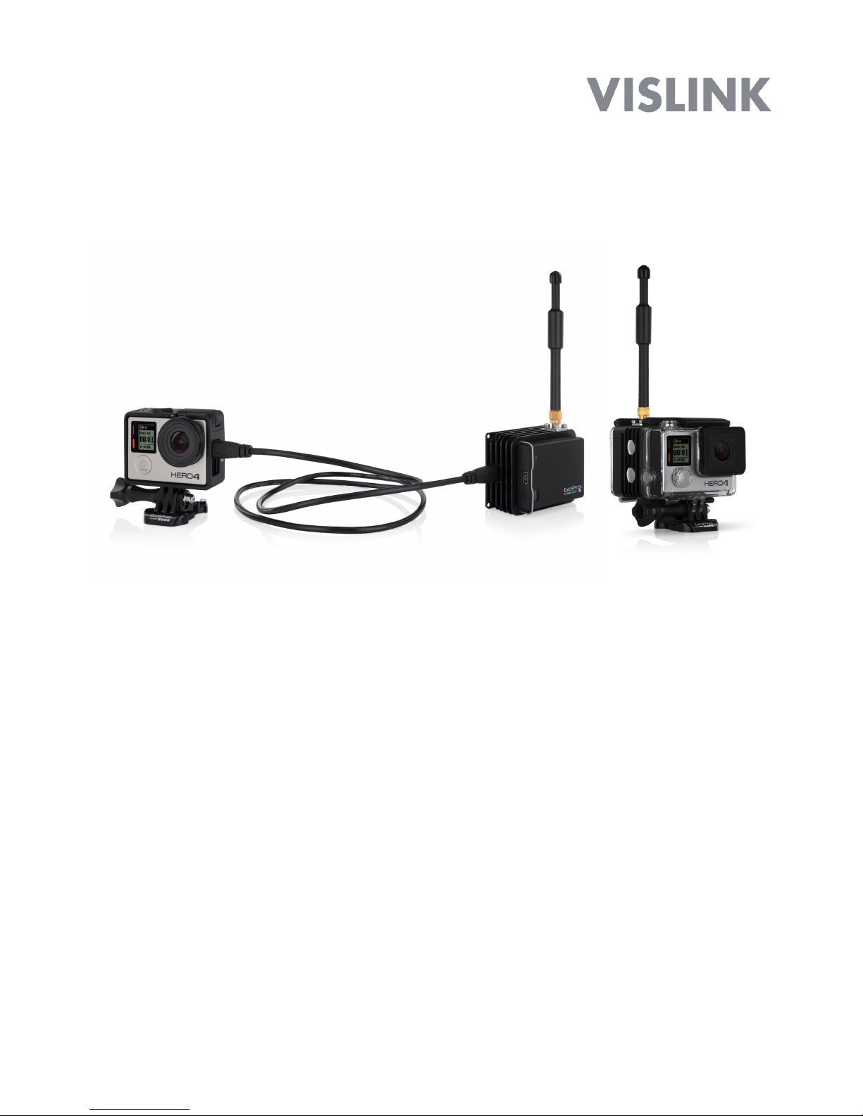
The HEROCast transmitter enables professional broadcasters to deliver engaging, live
content with immersive POV footage and unique perspectives that are synonymous with
GoPro. HEROCast integrates with GoPro cameras and its ecosystem of mounts, and
delivers the most versatile, mountable broadcast solution available. In addition, HEROCast
transmits high definition 1080/60fps and 720/60fps video using H.264 encoding with low
glass-to-glass latency.
Two options are available:
•HEROCast is available as an independent unit that can be connected to a GoPro
camera via a lockable HDMI cable, which is optimal for body mounting and
engaging POV shots.
•The HEROCast BacPac directly connects to the housing of a GoPro camera,
delivering an integrated, water-resistant solution for immersive live action footage.
Both configurations are compatible with HERO4 Black, HERO4 Silver, and
HERO3+ Black cameras.
The transmitters operate in the professional licensed frequency band of 1.95GHz –
2.7GHz, and require a matching RF diversity receive infrastructure.
The software provided on the USB drive included in the package contains all the software
required to enable operation. Once configured by the app, operation of the transmitter is as
basic as switching on HERO4.
For help or answers to questions not addressed in this manual, email
UKsupport@vislink.com or call Vislink:
•US: +1 (888) 777 9221
•UK:+44 (0) 1787 226227

!
!
3
3. SPECIFICATIONS
3.1. COMPLIANCE STANDARDS
This device is in compliance with the standards listed below:
•Europe (CE)!–!
o EN 302 064-2 V1.1.1!
o EN 301 489-1 V1.9.2!
o EN 301 489-28 V1.1.1!
o RoHS !
o WEEE!
•FCC
o FCC Part 74F!
o SAR!
o SAR Canada exempt.!
o Safety to EN60065:2014!
•Proposition 65 (California)!
3.2. VIDEO SPECIFICATIONS
•HDMI Type-D plug input
•H.264 low latency HD AVC video encoder/MPEG-4 Part 10 Video bit rates of 3.732
Mbps to 31.688 Mbps
•Audio encoding using MPEG-1 Layer 2
Supported Broadcast Standards
720P/50
720P/59.94
1080I/50
1080I/59.94
•Based upon the broadcast standard selected, there are several choices of modes on
the GoPro cameras which can be used to ensure video is available and is being
transmitted. A complete table of supported modes can be found in Section 7.

!
!
4
3.3. RF SPECIFICATIONS
Modulation Types
DVB-T
Modulation Modes
QPSK
16-QAM
64-QAM
OFDM Guard Interval
1/32
1/16
1/8
1/4
Modulation Forward error
Correction (FEC)
1/2
2/3
3/4
5/6
7/8
Modulation Polarity
Normal
Inverted
Modulation Bandwidth
6MHz
7MHz
8MHz
Transmitter Power
10mW
50mW
80mW
100mW
Carrier Frequency
1.95GHz – 2.70GHz
Video Standards
720P/50
720P/59.94
1080I/50
1080I/59.94
!
!

!
!
5
4. HEROCAST SETUP
4.1. Parts and Illustration of HEROCast
4.2. Setting Up HEROCast
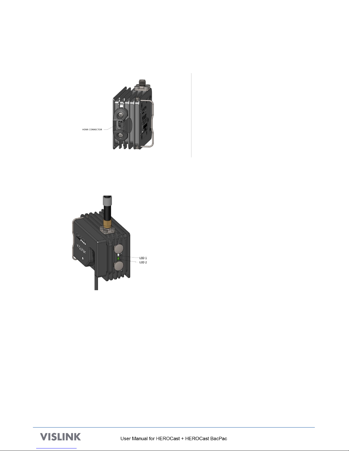
A. Connect the antenna using the tools provided. Do not over tighten. The figure
below shows the antenna connector.
!
B. Attach the battery or the battery eliminator. If you are setting up HEROCast for the
first time, make sure that the battery is fully charged. If the battery is not charged,
use the battery eliminator for the setup. The battery eliminator and battery can be
swapped without reconfiguring the device.
Insert the hooked end of the battery into the HEROCast system first. Note the
notch where the hook at the end of the battery must be inserted. Insert the hook
and then press the battery connector firmly into the transmitter connector.
Swing the spring clip over the back of the battery.
!
!
!
!
6
C. Power on the camera.
D. Select a micro-HDMI cable of a suitable length from the set of cables provided in
the case. Attach one end of the cable to the HDMI connector (shown below).
Connect the other end to the camera.
Note: The camera must be powered on when connecting the HDMI cable.
E. When the camera is connected, two LEDs alternate between red and green, indicating that
the software is loading. As shown in the figure below, when HEROCast is transmitting, a
steady green LED is visible.
!
!
F. HEROCast has several configuration options allowing for precise specification of the
transmission protocols and video encoding. To configure HEROCast or to update the
firmware, refer to Section 5.
!

!
!
7
4.3. Parts and Illustration of HEROCast BacPac
4.4. Setting Up HEROCast BacPac
A. Connect the antenna using the tools provided. Do not over tighten. The figure
below shows the antenna connector with an antenna in place.
!
B. Attach the battery or the battery eliminator. If you are setting up HEROCast for the
first time, make sure that the battery is fully charged. If the battery is not charged,
use the battery eliminator for the setup. The battery eliminator and battery can be
swapped without reconfiguring the device.
As shown below, insert the hooked end of the battery into the HEROCast BacPac
first, then press the battery connector firmly into the transmitter connector.
!
!
!
8
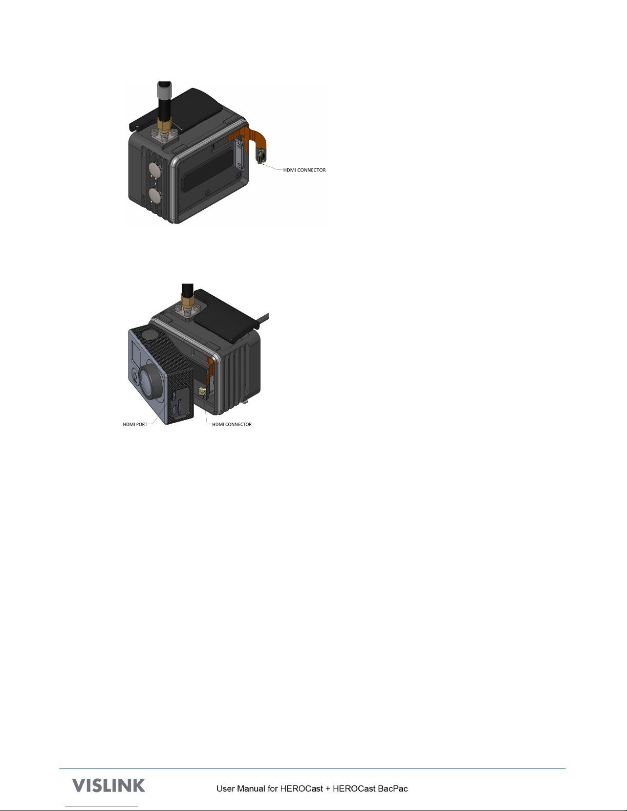
C. Mount the camera to the HEROCast BacPac, so that the free end of the mini-
HDMI connector is clear of the frame and can be connected to the camera.
The figure below shows the correct positioning prior to pushing the camera in
place. Once the camera is in place, connect the HDMI connector to the camera.
!
D. When the camera is connected, two LEDs alternate between red and green, indicating that
the software is loading. When HEROCast is transmitting, a steady green LED is visible.
!
E. HEROCast BacPac has several configuration options allowing for precise specification of
the transmission protocols and video encoding. To configure HEROCast BacPac or to
update the firmware, refer to Section 5.

!
!
9
5. CONFIGURATION
The configuration steps for HEROCast and HEROCast BacPac are identical and the same
application works with either device. While we only reference HEROCast in this section, the steps
and methods apply to HEROCast BacPac, as well.
Required elements for configuration:
•The USB drive containing the software (shipped with HEROCast)
•A USB cable allowing HEROCast to be connected to a computer (shipped with HEROCast)
•A computer:
oMac running OS version 10.9 or later
oWindows running Windows 7 or later
5.1. Preparing the Computer and Camera
This preparation is required the first time HEROCast is configured.
A. Connect the included USB drive to your computer. All of the software referenced in this
section can be found on the USB drive.
B. Update the camera software:
a. Identify your camera model. HEROCast is compatible with HERO4 Black, HERO4
Silver, and HERO3+ Black.
b. Open the 1 - GoPro Camera Update folder.
c. From the appropriate camera model folder, drag the sub-folder named UPDATE to a
blank microSD card (the same software is used for HERO4 Black and HERO4
Silver).
d. With the camera powered off, insert the microSD card and power on the camera.
The update begins automatically and the camera restarts numerous times during the
process.
e. Verify that the camera software was updated.
•For HERO4 cameras, the version number must be 2.83.01 or higher
•For HERO3+ cameras, the version number must be 3.84 or higher
If the version number shown is not correct, repeat the update steps. Be sure you are
using the correct software for your camera model.
!
!
10
C. Install the HEROCast USB driver:
a. Open the 2 - USB Driver folder.!
b. Open the appropriate installer for your computer system. !
oFor Mac, double-click HEROCast FTDI USB Drivers for Mac.dmg.!
oFor Windows, double-click HEROCast FTDI USB Drivers for Windows.exe. !
D. Install the HEROCast setup application and reset HEROCast:
a. Open the 3 - HEROCast Setup Application folder.
b. Open the appropriate file for your computer system.
oFor Mac, double-click HEROCast Setup Application for Mac.dmg, and then drag
it to the application folder.
oFor Windows: Double-click HEROCast Setup Application for Windows.exe.
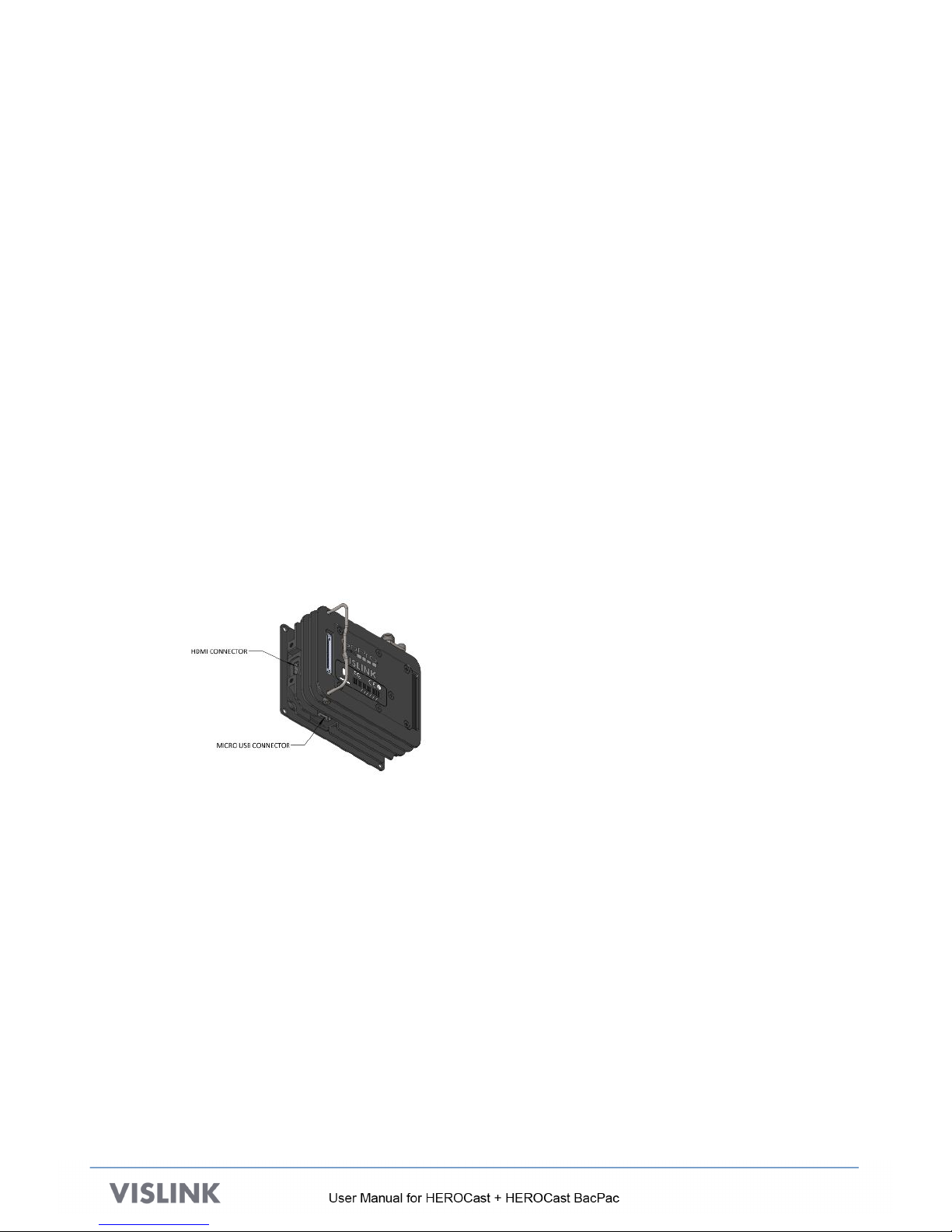
5.2. Connecting HEROCast to the Computer
A. Connect the HDMI from the GoPro camera to the HEROCast.
B. Use the included USB cable to connect the computer to the USB port of the HEROCast.
The USB cable is along the bottom of the device as indicated below.
Follow the directions in Section 4.2 to set up HEROCast.
!

!
!
11
5.3. Configuring HEROCast Using the HEROCast Application
A. Open the HEROCast application on your computer.
oFor Mac, it can be found in the Applications Folder
oFor Windows, it can be found in the GoPro directory under All Programs in the
Windows menu.
B. From the main menu, select Connect.
The application attempts to locate the HEROCast device connected to the computer. Either
the default name (HEROCast) or a name created during configuration of the device appears.
When upgrading firmware, the device may appear as a COM port.
C. Click the name of the device that you want to control.!
!
D. Click the back arrow (<) to return to the main menu.
!
!
12
The green status light indicates that the application is connected to a HEROCast device.
HEROCast can be configured either by individually selecting options under settings or
selecting a pre-set configuration.
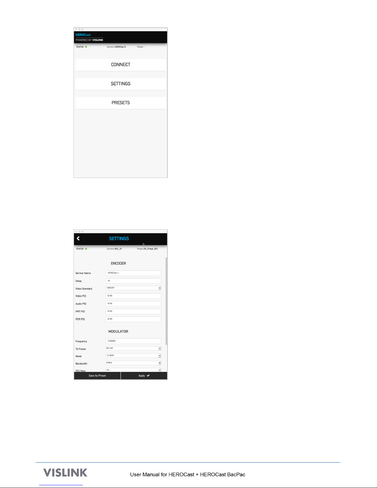
E. Click Settings to open this screen:
You can modify parameters related to video in the Encoder menu and in the RF
transmission in the Modulator menu. The table at the end of this section describes
the different options.
After making changes, you can save the set as a preset by clicking Save as Preset.
F. To return to the main menu, click the back arrow (<).
!

!
!
13
G. To use a preset, click Presets from the main menu to open the presets list.
Several options are available within this menu.
oTo edit a preset, click the edit icon.
oTo apply a preset to the camera, click the last icon in the row, then drag
and drop the preset from the More Presets section to the Applied to the
Camera section.
oTo restore the unit to its factory settings, click Reset to Defaults.
oTo delete all presets, click Delete All.
oTo return to the main menu to select another connected device, click the
back arrow (<), then click Connect.

!
!
14
5.4. Available Settings on the HEROCast Application
Menu&Option&
&Values&
Service!Name!
20!character!string!
Delay!
Integer!number!of!milliseconds!
Video!Standard!
720p/50!
720p/59!
1080i/50!
1080i/59!
Video!PID!
32!<=!n!<=!8190!
Audio!PID!
32!<=!n!<=!8190!
PCR!PID!
32!<=!n!<=!8190!
Frequency(MHz)!
1950.00!<=!n!<=!2700.00!
TX!Power!
10mW!
50mW!
80mW!
100mW!
Mode!
QPSK!
16[QAM!
64[QAM!
Bandwidth!
6!MHz!
7!MHz!
8!MHz!
FEC!Rate!
1/2!
2/3!
3/4!
5/6!
7/8!
Guard!
1/32!
1/16!
1/8!
1/4!
Carrier!Offset!
0!
+1!
[1!
Polarity!
Normal!
Inverted!
!
!
15
6. UPGRADING HEROCAST
The upgrade procedures for HEROCast and HEROCast BacPac are identical. While we only
reference HEROCast in this section, the steps and methods apply to HEROCast BacPac, as well.
Required elements for configuration:
•The USB drive containing the software (shipped with HEROCast) or the software update file on
the computer that is connected to HEROCast
•A GoPro that is compatible with HEROCast
•Included micro-USB cable !
•A computer:
oMac running OS version 10.9 later
oWindows running Windows 7 or later
•A fully charged battery or a battery eliminator!
6.1. Setup
A. Set up HEROCast as described in Section 4.2.
B. Ensure that the HEROCast Application is up and running. If not, install it as described in
Section 5.
C. Power the camera on.
D. Remove the power from HEROCast by removing the battery or removing the battery
eliminator.
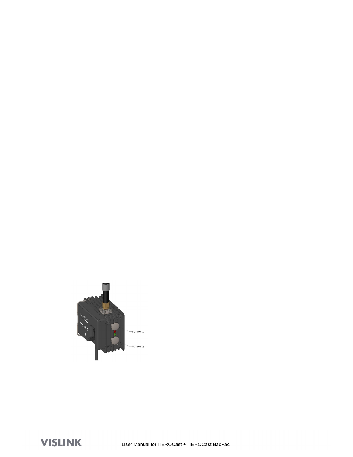
E. While holding down the two buttons on the side of HEROCast, reconnect the battery.
The two LEDs on the side of the HEROCast begin quickly alternating amber and green,
indicating the HEROCast is booting up into upgrade mode. When the unit is in upgrade
mode, both LEDs are red.
!
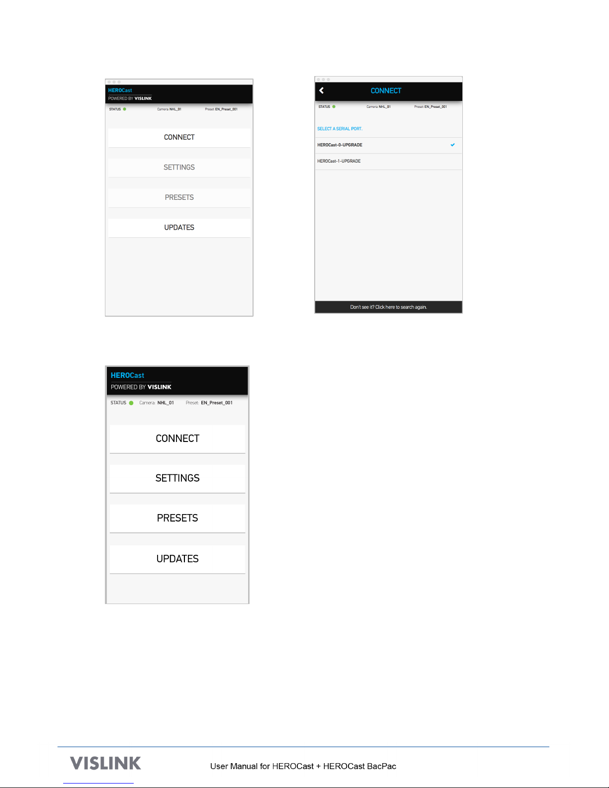
F. In the HEROCast application, tap Connect.
!
!
!
16
G. Select the HEROCast device that you want to upgrade.
H. Return to the main menu.An Updates option now appears.
!
!

!
!
17
I. Select Updates, then select Choose Firmware Update File.
!
J. Select Apply Update to start the upgrade.
Current Software Versions
Upgrade Progress Bar
Apply Update button
(Starts the upgrade)
!
Once the upgrade is completed, the unit re-starts into normal operation mode.
6.2. Tips for Upgrade Issues
•Before connecting the USB cable to HEROCast, be sure HEROCast is completely powered
up and displaying non-flashing LEDs.
•Always use a fully charged battery when connecting HEROCast to your Mac/PC. If the
HEROCast battery is nearly out of power, unplug the USB cable before the battery runs out
of power.
•If your computer does not detect HEROCast, unplug the USB cable, wait for a moment and
plug it back in. Select “Search again” in the Connect page. If needed, repeat these steps until
HEROCast is detected.
•Always use the latest FTDI drivers for your PC.
Note: On Mac computers, remove the default Apple FTDI serial USB driver to allow
HEROCast to work. If HEROCast does not work, run the Uninstall Apple FTDI Driver
app/script on the USB drive that was included with HEROCast.

!
!
18
7. Q&A
1. MY VIDEO IS NOT BEING RECEIVED. WHAT SHOULD I CHECK?
Assuming the receive infrastructure is known to be working, the following is a list of
potential areas that would stop your transmission from being received:
•Ensure that no other transmitter is on the same frequency as your transmitter.
•Ensure that the lower status LED is solid green.
•Ensure that the HDMI or integral HDMI interface is still connected.
•Check for physical damage to the antenna.
2. WHAT DO THE LED COLORS INDICATE?
The LED colors indicate the status of the transmitter, as described below.
LED
State
Description
Upper and lower
Blinking red and green
Initializing
Lower
Solid Green
Ready to transmit
Lower
Blinking green
RF transmission is off
Lower
Solid Amber
No video from camera
Lower
Blinking amber
Wrong video format setting
on camera
Lower
Solid Red
Cannot detect camera
Lower
Blinking red
No camera connected
3. WHAT ARE THE TRADEOFFS BETWEEN VARIOUS SETTINGS?
The choice of modulation type, FEC, Guard Interval, and Bandwidth affect the range of the
transmission from the HEROCast transmitter, and the perceived video quality.
Modulation type – QPSK provides a more resilient RF connection than 64QAM, but the available
video data rate is reduced, lowering the perceived quality. If the distance to the receiver is small,
64QAM could give the best picture quality.
FEC (forward error correction) – ½is more robust than 7/8, but the available video bitrate is
reduced, lowering the perceived quality. If the environment is non-reflective and distances short,
then 7/8 could give the highest picture quality.
Guard Interval – ¼is more tolerant to echoes and reflections than 1/32, but the available video
bitrate is reduced, lowering the perceived quality.
Bandwidth – Defined by the available RF spectrum at the transmitter site. 6MHz channel
supports lower video bit rate than an 8MHz channel.
The 4 parameters should be traded off, taking into account the distance between the transmitter
and receiver, and the environment (whether it be line-of-sight or a highly reflective built up
area).
This manual suits for next models
1
Table of contents
Other Vislink Transmitter manuals


Popular Transmitter manuals by other brands

Davis Instruments
Davis Instruments Anemometer Transmitter Kit installation manual

Minebea
Minebea NS100A instruction manual

Audio Authority
Audio Authority HBT200T user manual

Siemens
Siemens SITRANS F MASS 6000 Ex d operating instructions

Beninca
Beninca RF manual

Nautel
Nautel NX Series Operation and maintenance


