Nidac Presco PRX User manual
1
N761
PRX
“Series 2”
Mullion Style
Indoor Proximity
Reader
Installation Manual
4th Edition
™
2
PROTECTION.
The NIDAC Presco™ system has a high immunity to all types of
static, EMF, and RF transmissions including those of Police and
CB radio systems. Reverse polarity protection is provided.
WARRANTY.
NIDAC SECURITY PTY. LTD. will repair or replace this product
if proven to be faulty (excluding accidental or malicious damage)
under the 36 month warranty offered from the date of purchase.
As NIDAC SECURITY PTY. LTD. or it’s agents do not perform the
final installation, inspection or training in the use of this product,
they cannot be held liable for injury, loss or damage directly or
consequentially arising from the use or misuse of this product.
Presco™ is a registered Trade Mark belonging to NIDAC
SECURITY PTY. LTD. The Presco™ system is protected by
provisional and pending patents in various countries including
Australia.
The software design is protected internationally and remains the
intellectual property of NIDAC SECURITY PTY. LTD.
Design improvement and specifications are subject to change
without notice. All designs are copyright 1992 -2004.
Designed and Manufactured by:
NIDAC SECURITY PTY. LTD.
2 Cromwell Street
Burwood, Victoria Phone:61 3 9808 6244
Australia 3125 Fax: 61 3 9808 9335
“When you’re serious about security”
Revision 1.0
PRX
Series
2
Instructions.doc
2/0
7/04
3
OVERVIEW
The Presco™ PRX Proximity Reader by Nidac is an advanced,
self contained RFID (Radio Frequency IDentification)
contactless reader. It is capable of interfacing to either a
Wiegand input control panel or to Nidac’s new range of
Presco™ PAC decoders.
The mullion (or architrave) styling makes the PRX suitable for
door frame mounting as well as other mounting positions.
OPERATION
Connected to a Presco™ PAC decoder
The LED on the reader is red when ready to read a Presco™
prox card. When a card is presented to the front of the reader
the LED momentarily turns orange to indicate that the PRX has
read it. The code is then transmitted to the PAC decoder.
If the card is valid the PRX will respond with 1 or 2 short beeps
and the LED will change to green (provided the blue wire is
connected as shown in the wiring diagram) for the time the ELC
relay is active (door is released).
If the card is invalid the PRX will respond with a “blarp” (long
beep) and the LED will remain red.
Connected to a Wiegand controller
The LED on the reader is red when ready to read a Presco™
prox card. When a card is presented to the front of the reader
the LED momentarily turns orange and the internal buzzer gives
a short beep to indicate that the PRX has read it. The code is
then transmitted to the Wiegand controller.
The LED can be made to change colour to green by the
controller by applying +5 to 15 Volts D.C. to the blue wire.
4
SPECIFICATIONS
Voltage:-8 to 15Volts D.C.
linear power supply recommended.
Current:-65mA max @ 15Volts D.C.
Size:-150mm x 44mm x 20mm.
Outputs:-26 bit Wiegand,Pulse Width = 50µs,
Pulse Separation = 2ms.
and Presco™PAC decoder format.
Read Range:-Up to 12cm (4½”).
Wiring Distance:-PRX to Presco™ PAC Decoder = 1Km
(100Ω max. return resistance, unshielded
cable).
PRX to Wiegand controller with shielded cable.
Wire Gauge Wiring Distance
22 AWG 150m (490 ft)
24 AWG 100m (330 ft)
26 AWG 60m (195 ft)
28 AWG 40m (130 ft)
Excitation Frequency:-125 ± 5 KHz.
Operating Temperature:-0°C to 70°C.
36 month (3 year) manufacturer’s warranty.
Designed and manufactured in Australia.
WIRE COLOURS
Red -+8 to 15Volts D.C.
Black -Ground (0 Volts).
Green -Wiegand Data 0.
Yellow -Wiegand Data 1.
Blue -LED Control.
White -Presco™ PAC DTA line (connect to Ground when
using Wiegand).
Drain -Shield/Ground (connect to Ground at controller).
5
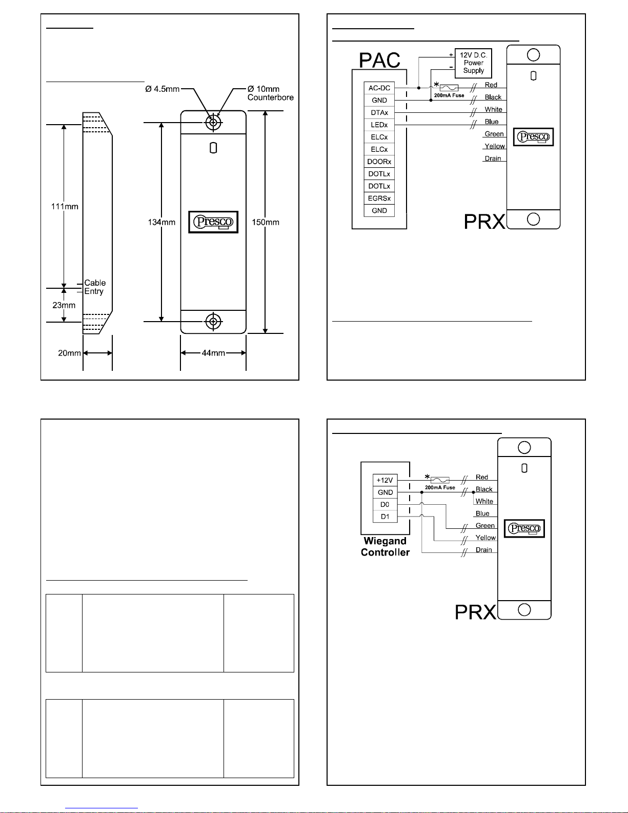
MOUNTING
Use the supplied mounting template to mark the cable entry and
two mounting holes. Note that the cable entry to the PRX is
near the bottom screw hole.
DIMENSION DIAGRAMS
6
WIRING DIAGRAMS
Connecting the PRX to a Presco™ PAC decoder
Note that the Green, Yellow and Drain wires on the PRX are not
connected when it is used with a PAC decoder.
* Use a 200mA inline fuse to protect the power supply from short
circuiting if PRX wires are tampered with. This is particularly
important when using fail safe (power to lock) locking
mechanisms.
Programming Prox cards & tags into a PAC decoder
To program a proximity card or tag into a PAC decoder follow
the same steps as shown in the decoder manual for
programming a new user code. When it comes to the stage to
enter the user code simply present the card or tag to the PRX
that is connected to the same input as the programming keypad,
7
or alternatively enter the 9 digit code for the proximity card, note
that this code may contain star (*) and hash (#) symbols and that
leading zeroes (0) need to be entered.
Example
This example uses a PAC1 decoder programming a momentary
operation proximity card or tag into memory location 001.
1. Put the PAC1 into program mode using the management
code or button on the PAC1.
2. Open the memory location in which the Prox card is to be
stored. * 001 1 E
3. Present the proximity card or tag to the PRX.
4. Take the decoder out of program mode.
Connecting the PRX to a CS Technologies controller
Using Presco format CS controller
4 Door Controller 2 Door Controller
PRX Door 1 Door 2 Door 3 Door 4 Door 1 Door 2
Red +12V +12V +12V +12V +12V +12V
Black Gnd Gnd Gnd Gnd Gnd Gnd
White IN1 IN3 IN5 IN7 IN1 IN3
Blue N/C N/C N/C N/C N/C N/C
Green N/C N/C N/C N/C N/C N/C
Yellow N/C N/C N/C N/C N/C N/C
Drain N/C N/C N/C N/C N/C N/C
N/C = No Connection
Using Wiegand format CS controller
4 Door Controller 2 Door Controller
PRX Door 1 Door 2 Door 3 Door 4 Door 1 Door 2
Red +12V +12V +12V +12V +12V +12V
Black Gnd Gnd Gnd Gnd Gnd Gnd
White Gnd Gnd Gnd Gnd Gnd Gnd
Blue OUT1 OUT2 OUT3 OUT4 OUT1 OUT2
Green IN1 IN3 IN5 IN7 IN1 IN3
Yellow IN2 IN4 IN6 IN8 IN2 IN4
Drain Gnd Gnd Gnd Gnd Gnd Gnd
8
Connecting the PRX to a Wiegand controller
Note that the White wire is connected to GND (Black wire) at the
PRX, but the Drain is connected to GND at the Wiegand
controller.
The Blue wire controls the LED on the PRX. When a high
voltage (+5 to 15V D.C.) is applied to this wire the LED will
change to Green. This is normally connected to the switched
positive side of the Electronic door release mechanism.
* If the controller does not provide a fused output for readers use
a 200mA inline fuse to protect the power supply from short
circuiting if PRX wires are tampered with.
Table of contents
Other Nidac Card Reader manuals


