NIFEITOR GQB-48100-01-01-J User manual
1
Rack Mounted Lithium Battery Series
User Manual
GQB-48100-01-01-J

2
Content
1 Safety Information ............................................................................................................................ 3
1.1 General Safety ..................................................................................................................3
1.2 Personal Safety.................................................................................................................3
1.3 Electrical Safety ................................................................................................................ 3
1.4 Transportation Safety ..................................................................................................... 5
2 Product Information ......................................................................................................................... 5
2.1 Battery Overview................................................................................................................5
2.2 Appearance……………………………………………………………………………………………………… 5
2.3 Front Panel ..........................................................................................................................6
2.4Dimensions.......................................................................................................................... 8
2.5Capacity Options................................................................................................................9
3 Attentions............................................................................................................................................9
4 Specifications....................................................................................................................................10

3
1 Safety Information
1.1 General Safety
Please carefully read the manual safety precautions, and observe all the safety instructions on the
equipment and in this document.
The "DANGER”,"WARNING", and "NOTICE” statements in this document do not cover all the safety
instructions. They are only supplements to the safety instructions.
For user safety and utilization efficiency of this manual, a list of symbols are designed to alert people
from danger. You must understand and comply with the emphasized information to avoid personal injury
and property damage. Relative safety symbols have been listed below.
DANGER indicates a hazardous situation which, if
not avoided will result in serious injury and fire.
WARNING indicates a hazardous situation which, if
not avoided will result in property loss or void
warranty.
NOTICE indicates normal situation which, if not
avoided will result in that battery doesn't work.
Follow local laws and regulations when installing, operating, or maintaining the equipment. The safety
instructions in this document are only supplements to local laws and regulations.
1.2 Personal Safety
Personal Requirements
People who plan to install or maintain battery equipment must be trained, understood all necessary
safety precautions, and are able to perform all operations correctly.
Only qualified professionals or trained people are allowed to install, operate, and maintain the
equipment.
Personal Safety
Do not place battery at a children or pet touchable area.
Do not touch the energized battery, as the enclosure is hot.
Do not touch the energized battery terminals.
Do not stand on, lean on, or sit on the battery.
1.3 Electrical Safety
Symbols on battery
There are some electrical symbols on battery relate to electrical safety. Please make sure you have fully
Danger
Warning
Notice
4
understand them before installation.
Electrical danger
Voltage exits when the battery is
powered on. Only qualified engineers are
allowed to operate.
Earth connector
Earth connection.
DC positive and
negative connectors
Identify positive and negative connectors
of DC power source.
CE mark
The product meets CE certification.
WEEE tag
Can't leave battery as garbage disposal.
Recycle
Battery can be recycled.
Electrical Safety
Before installation, ensure that the equipment is intact. Otherwise, electric shocks or fire may
occur.
Do not connect or disconnect power cables when battery is power-on. Which may cause electric
arcs and sparks more overfire or personal injury. Before connecting a power cable, check the
positive or negative connectors are correct.
Do not parallel connection with different batteries.
Do not connect battery with AC directly.
Do not connect battery with PV wiring directly.
Do not connect batteries in series.
Do not connect battery to faulty or unqualified inverter or charger.
Do not create short circuits with the external connection.
Make sure the grid is cut off and the battery is powered off before maintenance.
Make sure the earth cable is connected correctly before operation.
Recharge battery in every six months.
Recharge battery within 10 days after battery is fully discharged.
Please engage greater than or equal to two batteries when maximum charge current is more than
80A.
Make sure battery cable placement is installed correctly.
When the battery is being installed or repaired, make sure the battery is powered off and using a
multimeter to make sure there is no voltage in the positive and negative terminals.
Please use dedicated insulated tools for install and maintenance.
Please make sure all batteries are power-off when multiple parallel connection.
Please check lights on sequence when battery power-on.
Please make sure communication connection connect correctly with battery and inverter.
Please make sure ADDS dip switch settings are correctly for single or multiple batteries.
Please check inverter alarm or SOC reading when there is BMS communicated with inverter.
Environment Safety

5
Ensure that the equipment is installed in a dry and well-ventilated
environment.
The installation position must be away from direct sunlight and rain.
The installation position must be far away from fire sources.
The installation position must be far away from water sources such as taps, sewer pipes, and
sprinklers to prevent water seepage.
The bracket must be installed solidly and horizontally.
Do not expose the equipment to flammable or explosive gas or smoke.
Do not perform any operation on the equipment in such environments.
The operation and service life of the battery depends on the operating temperature. Operate the
battery at a temperature equal to or better than the ambient temperature. The recommended
operating temperature range is from 0°C to 30°C.
1.4 Transportation Safety
The products passed certification UN38.3.
The products have MSDS.
The products belong to class 9 dangerous goods.
Please protect the packing case from the below situations.
Being dampened by rains, snows, or falling into water.
Falling or mechanical impact.
Being upside-down or tilted.
2 Product Information
2.1 Battery Overview
The battery is a rack lithium battery pack which consists of long span LiFePO4 battery cells and
functional BMS. It can store and release electric energy based on the requirements of the inverter
controller. It is mainly for home energy storage system.
Features
LiFePO4 prismatic cell
6000 cycles @0.5C conditions
Maximum 1C charge and discharge capability
Wall mounted IP 21 grade
Be extended to 8packs maximum
Protective and active BMS allows greater reliability and control
IP 21 grade
Building in terminal design
Fully recyclable at the end of life
Compact
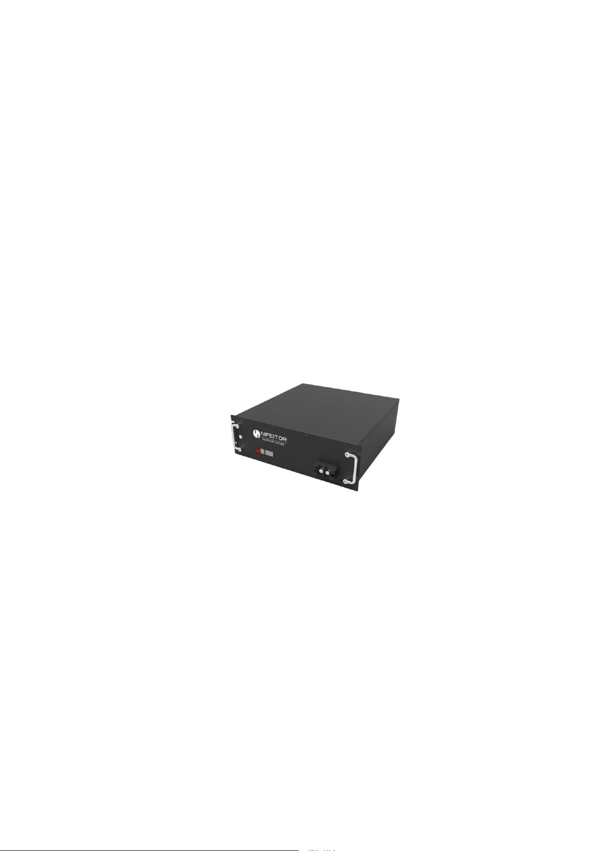
2.2Appearance

6
2.3 Front Panel
1) Chassis mounting ears: For product installation and fixation, it can be
installed in a 19-inch standard cabinet or an anti-vibration iron frame.
2) Chassis handle: easy to carry, move and install.
3) Switch: BMS switch, when it is turned off, the BMS can be put to sleep and the
charge and discharge MOS transistors will be turned off at the same time;
normal operation will be restored after it is turned on.
Note: Please do not turn on the system switch when the product is not in
use to avoid self-consuming the lithium battery.
4) Switch: BMS switch, when it is turned off, the BMS can be put to sleep and the
charge and discharge MOS transistors will be turned off at the same time;
normal operation will be restored after it is turned on.
Note: Please do not turn on the system switch when the product is not in
use to avoid self-consuming the lithium battery.
5) Reset switch: When the battery is abnormal or dormant, the reset button can
be used to restart and wake up the battery to ensure the stable operation of
the system.
6) CAN COMM:
BMS supports the function of CAN communication for battery pack uploading,
baud rate of 500K. CAN communication interface adopts 8P8C network cable
interface. It can communicate with inverter or CAN TEST through CAN interface.
When the battery pack is connected, RS485 communication is connected,the
data, status and information of the battery pack can be uploaded to inverte
through CAN communication.
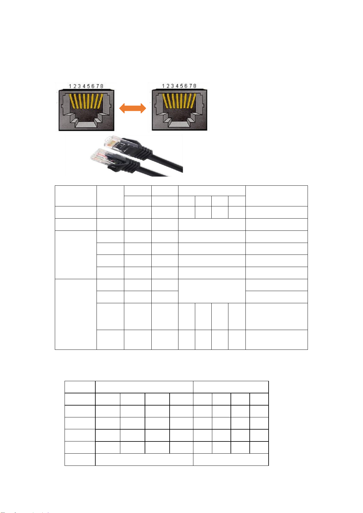
CAN communication interface definition:
7) RS485 COMM
The BMS has RS485 communication for battery pack collection, and the
baud rate is 9600bps. RS485 communication interface adopts 8P8C
network cable interface. RS485 pin interface definition (RJ45-8P8C)
Pins
Definition
1、2、7、8
NC
4
CAN-H
5
CAN-L
3、6
GND
Pins
Definition
1、8
RS485-B
2、7
RS485-A
3、6
GND
4、5
NC(empty)
7
8) Parallel communication
When multiple packs are connected in parallel, the RS485 interface is used as
the parallel communication interface. The master pack can read the sum of the
slave battery data of all parallel packs through the RS485 interfaces.
RS485 parallel connection: PIN TO PIN
9) LED indicators
System
Status
RUN
ALM
SOC
Definition
●
●
●
●
●
●
switch on
sleeping
off
off
off
off
off
off
All off
standby
normal
on
off
SOC indicators
standby
Charging
charging
normal
on
off
SOC indicators
Flashing
OC ALM
on
Flashing
SOC indicators
Flashing
OV ALM
on
off
SOC indicators
OT ALM
on
Flashing
SOC indicators
Discharging
normal
Flashing
off
SOC indicators
SOC indicators
alarm
Flashing
Flashing
All Pro-
tections
off
on
off
off
off
off
Fully discharged or 48
hours no instructions,
going into sleep mode
UV Pro-
tections
off
off
off
off
off
off
Stop discharge
10) Red alarm indicator, normally off. And always on under fault conditions
with beep.
11) SOC indicator, four green LED lights to display the real-time SOC capacity
of the lithium battery pack.
Status
charge
discharge
SOC
L4●
L3●
L2●
L1●
L4●
L3●
L2●
L1●
0~25%
off
off
off
flashing
off
off
off
on
25~50%
off
off
flashing
on
off
off
on
on
50~75%
off
flashing
on
on
off
on
on
on
≥75%
flashing
on
on
on
on
on
on
on
RUN●
on
flashing

8
12) Grounding terminal: connect M4 cold-pressed terminal to AC power
ground.
13) DIP Switches
Parallel DIP switch definition: For multi-battery communication when the
battery packs are connected in parallel, use the DIP switch to distinguish
different pack addresses, and the hardware address can be set by the DIP
switch on the panel below.
2.4 Dimensions

9
2.5 Capacity Options
The battery can be parallelly connected for extending power(kW) and energy(kWh).
The maximum power(kW) is limited by main cables from master battery to inverter.
The maximum 8 battery packs can be parallelly communicated.
For example, ONE PACK is 4.8kWh,
4.8kWh 9.6kWh 19.2kWh
AND MORE ……
3 Attentions
Before using the battery pack, please read the manual carefully to understand
the usage and precautions;
Non-professionals shall not disassemble the battery without authorization;
Be sure to use the original special charger for charging or the charger agreed by
both parties;
During use or storage, if you find abnormal heating, discoloration, deformation
or other abnormalities in the battery, please stop using the battery;
The working temperature of the battery is -10~55℃;
The storage temperature of the battery is -10~35℃, please place the battery in a
dry and cool environment
Do not bump, apply external force or make the battery fall from high altitude
during use;
If the battery is not used for a long time, the battery pack needs to be charged to
more than 80%, turn off the power switch, and store it in a ventilated and dry
environment.

10
4 Specifications
Item Specifications remark
GQB-48100-01-01-J
Battery Type LiFePO4
Typical Capacity (Ah) 100Ah
Typical Voltage (V) 48V
Connection 1P15S
Voltage Working Range(V)
42V-54V
Single cell:
2.8V-3.6V
Working Temperature(℃)Charge: 0℃~+55℃,
Discharge: -20℃~+55℃
StorageTemperature(℃)-10℃~+35℃
Nominal Capacity (kWh) 4.8kWh
Max. Charge Current(A) 75A
Max. DischargeCurrent(A) 75A
Cycle Life >6000 25℃,0.5C,
85%DOD
SOC Accuracy <8%
Net Weight(kg) 45kg
Gross Weight(kg) 47kg
Dimensions(mm) 533x474x150mm D x W x H
Package Dimension (mm) 600*525*210mm
IP Grade IP21
Transportation SOC 30%
Cooling Nature
Table of contents
Popular Camera Accessories manuals by other brands


Panasonic
Panasonic KXCPG100 - VIDEO TELECONFERENCI operating instructions

Energizer
Energizer Digital Camera Battery NH50 Product data sheet

Kyocera
Kyocera YASHICA 28-85mm F3.5-4.5 MAGRO instruction manual

Fantasea
Fantasea FS-610 Operator's manual

Oben
Oben Lander Series Operation manual

Star Micronics
Star Micronics T400 user manual