Aquion Energy S Series User manual
Aquion Energy, Inc.
32 39th Street
Pittsburgh, PA 15201
+1 412.904.6400
www.aquionenergy.com AQ-OP-00016_C
S-Line and M-Line
Installation & Operation Manual
Battery Stack Model S30-0080
Battery Module Models M110-LS83, M110-L083

AQ-OP-00016_C
© 2016 Aquion Energy, Inc.
The information in this document is subject to periodic updates and changes. Upon any updates or
changes to the above-described material, Aquion Energy will provide new drawings and/or associated
documentation that will supersede those contained in this document. Contents are subject to change
without notice.
For the latest product documentation, visit http://info.aquionenergy.com/customer-portal or email
us at info@aquion-energy.com.
Warnings in This Document
WARNING WARNING indicates a hazardous situation that, if not avoided, could result in
death, injury, or damage.

i AQ-OP-00016_C
Table of Contents
1Introduction____________________________________________________________________ 1
1.1 About This Manual 1
1.2 Contact Information 1
2Product Information _____________________________________________________________ 1
2.1 Product Overview 1
2.2 Product Specification 1
2.3 UL Recognition 2
2.4 Cradle to Cradle Certification 2
2.5 M110-LS83 Electromagnetic Compatibility 2
2.5.1 FCC 2
2.5.2 CE 2
3Safety Information ______________________________________________________________ 3
3.1 Electrical Hazards 3
3.2 Electrical Safety 3
3.3 Chemical Hazards 3
3.4 Gas Emissions 3
3.5 Weight Hazards 4
3.6 Ingress Protection 4
3.7 Decommissioning Hazards 4
4Transportation and Receipt of Product _____________________________________________ 5
4.1 Shipping 5
4.1.1 Shipping Hazards 5
4.1.2 Shipping Requirements 5
4.2 Disassembly Hazards 5
4.3 Packaging 5
4.4 Delivery Inspection 5
5Installation _____________________________________________________________________ 7
5.1 Unpacking 7
5.2 Site Requirements 7
5.2.1 Exposure and Enclosure 7
5.2.2 Size and Weight 7
5.2.3 Ventilation 7
5.2.4 Humidity 8
5.2.5 Ambient Temperature 8
5.3 Moving 8
5.4 Placement 9
5.5 Battery Module Fuse Connection 9

ii AQ-OP-00016_C
6Electrical Integration____________________________________________________________ 11
6.1 Electrical Interfaces and Connections 11
6.1.1 Stack Connectors 11
6.1.2 Stack Accessories 11
6.1.3 Module Connectors 12
6.1.4 Module Accessories 15
6.1.5 Module Contactor Control 15
6.2 Product Wiring Diagrams 15
6.3 Racking/Scaling Systems 18
6.4 Cabling Requirements 18
6.5 Parallel Wiring 18
6.5.1 Monitoring 19
6.5.2 Overcurrent Protection 20
6.5.3 Grounding 20
7Commissioning ________________________________________________________________ 21
7.1 Initial Charge 21
7.2 Voltage Matching 21
7.3 Configuring Inverters and Charge Controllers 21
8Operation_____________________________________________________________________ 22
8.1 Operational Limits 22
8.1.1 Current 22
8.1.2 Voltage 22
8.1.3 Ambient Temperature 22
8.1.4 Configuration 22
8.2 Charge Profiles 22
8.2.1 Recommended Charge Profile 22
8.2.2 Boost Charge Profile 23
8.2.3 Three-Stage Charge Profile 24
8.3 State of Charge 24
8.3.1 Partial State of Charge 24
8.3.2 Determining State of Charge 24
8.4 Discharging 25
8.5 Self-Discharge 25
8.6 Long-Term Storage 25
8.7 Recycling and Disposal 25
8.8 Record Keeping 25
9Warranty _____________________________________________________________________ 26
10Technical Support______________________________________________________________ 26

1 AQ-OP-00016_C
1Introduction
1.1 About This Manual
This manual is intended to provide technical information and safe practices regarding receiving,
installing, and operating the Aquion Energy S30-0080 Battery Stack and the Aquion Energy
M110-LS83 and M110-L083 Battery Modules. For complete safety information, refer to the Safety
Data Sheet (SDS) included with your product shipment.
WARNING: Failure to follow the instructions in this document could result in fire, electric
shock, and/or other injury or damage.
1.2 Contact Information
Mail: Aquion Energy
32 39th Street
Pittsburgh, PA 15201
Telephone: +1 412.904.6400
Web:
www.aquionenergy.com
2Product Information
2.1 Product Overview
Aqueous Hybrid Ion (AHITM) batteries use non-toxic, non-corrosive materials to make the world’s only
clean and sustainable electrochemical storage solution. Aquion S-Line Battery Stacks and M-Line
Battery Modules provide long-duration, stationary storage for residential solar, off-grid, microgrid, and
energy management applications.
S-Line Battery Stack
The S-Line Battery Stack is the base component of Aquion Energy’s scalable energy solutions.
The S-Line battery stack connects eight Aquion batteries in series for a 48 V product. Aquion
offers one, unfused S-Line Battery Stack model: the S30-0080.
M-Line Battery Module
The M-Line Battery Module is a palletized energy storage module that serves as a stand-alone
system or as a building block for larger systems. The battery module connects twelve S30-0080
Battery Stacks in parallel. Aquion offers two M-Line Battery Module models:
Battery Module Model On-Board Sensing
M110-LS83 Voltage, current, temperature (VIS board)
M110-L083 None
2.2 Product Specification
Voltage curves, operational efficiency, capacity by charge and discharge currents, and more are on
the Product Specification Sheets: http://info.aquion-energy.com/customer-portal.

2 AQ-OP-00016_C
2.3 UL Recognition
The S-Line Battery Stack is UL recognized. The following UL certification tests have been completed:
+UL 1973-13 Overcharge
+UL 1973-14 Short Circuit
+UL 1973-15 Overdischarge Protection
+UL 1973-16 Temp and Ops
+UL 1973-17 Imbalanced Charging
+UL 1973-23 Vibration
+UL 1973-24 Shock
+UL 1973-25 Crush
+UL 1973-26 Static Force
+UL 1973-27 Impact
+UL 1973-30 Mold Stress
+UL 1973-31 Pressure Release
+UL 1973-32 Start-To-Discharge
+UL 1973-34 Resistance to Moisture
+UL 1973-35 Salt Fog
+UL 1973-36 External Fire Exposure
2.4 Cradle to Cradle Certification
The AHI S30-0080 Battery Stack is a Cradle to Cradle CertifiedTM Bronze1product. The Cradle to
Cradle Products Innovation Institute independently assesses and certifies products for material
health, material reutilization, renewable energy use and carbon management, water stewardship, and
social fairness. M110-LS83 and M110-L083 battery modules contain 12 of the S30-0080 stacks.
2.5 M110-LS83 Electromagnetic Compatibility
2.5.1 FCC
This device complies with part 15 of the FCC Rules. Operation is subject to the following two
conditions: (1) This device may not cause harmful interference, and (2) this device must accept any
interference received, including interference that may cause undesired operation.
Note: This equipment has been tested and found to comply with the limits for a Class A digital device,
pursuant to part 15 of the FCC Rules. These limits are designed to provide reasonable protection
against harmful interference when the equipment is operated in a commercial environment. This
equipment generates, uses, and can radiate radio frequency energy and, if not installed and used in
accordance with the instruction manual, may cause harmful interference to radio communications.
Operation of this equipment in a residential area is likely to cause harmful interference, in which case
the user will be required to correct the interference at his own expense.
2.5.2 CE
This product may cause interference if used in residential areas. Such use must be avoided unless the
user takes special measures to reduce electromagnetic emissions to prevent interference to the
reception of radio and television broadcasts.
1Cradle to Cradle CertifiedTM is a certification mark licensed by the Cradle to Cradle Products Innovation Institute.
3 AQ-OP-00016_C
3Safety Information
Only qualified individuals are to install and service battery systems.
3.1 Electrical Hazards
Never place foreign objects or tools in or on the unit. The metal parts of the battery terminals are
always live. Electrical hazards exist in the voltage and current ranges that are found in battery systems
and associated electronics.
S-Line Battery Stack
WARNING: Connecting battery stacks in series can lead to dangerously high voltages.
Any series configurations must be reviewed by Aquion prior to installation. When
connecting the unfused, S30-0080 stacks in parallel, Aquion recommends placing overcurrent
protection devices as close as possible to the DC bus.
3.2 Electrical Safety
S-Line Battery Stack
The maximum charge/discharge current of the S30-0080 is 17 A. The stacks must be protected
from overcurrent charge/discharge with appropriately rated overcurrent protection devices. If
grounding is required, see Section 6.5.3.
M-Line Battery Module
Each battery module includes twelve 1,000 V, 20 A fuses, one for each component battery stack.
The fuses do not come pre-installed (see Section 5.5 for fuse installation instructions). The
combined maximum fuse rating of 240 A is greater than the maximum rated current of the
module, 204 A, to allow for internal energy redistribution.
3.3 Chemical Hazards
AHI battery materials are non-toxic and present no chemical hazards. The AHI electrolyte is sodium-
sulfate-based saltwater with a neutral pH. In the unlikely event that the electrolyte comes in contact
with eyes or skin, thoroughly wash it out with water. Electrolyte residue on the battery terminal can be
wiped away with a cloth. A collection pan under the battery stack or module is not needed as the
electrolyte will not leak during normal operation, and any leaked electrolyte will not damage battery
surfaces or equipment. Refer to the SDS for additional information.
3.4 Gas Emissions
The battery may emit trace amounts of gas H2, O2, CO2, and CO during normal operation. These gases
do not accumulate in hazardous quantities in typical installations when the batteries are installed and

4 AQ-OP-00016_C
operated in accordance with the guidelines of this document. The battery has fully passed UL 1973
overcharge testing, an abuse test that includes monitoring for combustible vapor concentrations.
Overcharging the battery (outside of specified guidelines) will result in venting of some incremental
amounts of the gases listed above through the pressure relief valve.
3.5 Weight Hazards
S-Line Battery Stack
The battery stack weighs 118 kg (260 lbs) and must be transported and handled with appropriate
precautions. See Section 5.3 for moving and tilting restrictions.
M-Line Battery Module
The battery module weighs 1,504 kg (3,315 lbs) and must be transported and handled with
appropriate precautions. The use of forklift trucks and pallet jacks is recommended to move and
position battery modules.
3.6 Ingress Protection
The International Electrotechnical Commission publishes the International Protection (IP) Code, which
classifies the degrees of protection provided by electrical equipment enclosures against ingress of
solid particles and liquid.
Product
Solid Particle Protection Level 2
a
Liquid Ingress Protection Level 2
b
IP code
Battery stack
Confirmed
Confirmed
IP22
Battery module
Confirmed
Not tested
IP2X
a
protected from ingress of objects greater than 12.5 mm, such as fingers or similar objects (IP
#
#)
b
protected against harmful effects of ingress of dripping water when tilted up to 15 degrees, for a duration of 10 minutes or less (IP#
#
)
3.7 Decommissioning Hazards
AHI batteries are non-toxic and non-corrosive. Do not dump into any sewers, on the ground, or into
any body of water where water runs off into open bodies of water. Dispose of according to all federal,
state, and local regulations.
5 AQ-OP-00016_C
4Transportation and Receipt of Product
4.1 Shipping
4.1.1 Shipping Hazards
The shipping configurations for battery stacks have undergone a modified International Safe Transit
Association (ISTA) 3H shipping test. Modified ISTA 3H testing is pending for the battery module.
Aquion battery stacks and modules are shipped at a very low state of charge and voltage. See
Section 7.1 for initial charging instructions.
4.1.2 Shipping Requirements
S-Line and M-Line batteries should be shipped in an upright position and should not be tipped for an
extended period of time during shipping. Ensure that this restriction is communicated to the shipper
prior to transport. The affixed Tip-N-Tell indicators trip if the package experiences extreme tilt. See
Section 5.3 for moving and tilting restrictions.
4.2 Disassembly Hazards
WARNING: Do NOT attempt to disassemble battery stacks. Do NOT remove the nut on the
compression fixture on top of the stack. Battery stacks have been compressed to optimize
battery performance. Releasing this load could result in poor battery performance, permanent
damage to stack components, and/or injury.
4.3 Packaging
S-Line Battery Stack
Battery stacks arrive 12 or fewer to a pallet. They may be wrapped (U.S. shipments) or crated
(shipments outside the United States). On crated shipments, a Tip-N-Tell indicator and a Drop-
N-Tell indicator are affixed on the outside of the crate. On wrapped shipments, these indicators
are affixed on the outside of the wrapping.
M-Line Battery Module
Battery modules arrive wrapped and on a pallet. The Tip-N-Tell and Drop-N-Tell indicators are
affixed to the outside of the wrapping.
4.4 Delivery Inspection
Immediately upon delivery, inspect all hard goods for signs of damage or tipping during transit before
signing for the delivery. Any of the following MAY indicate damage during transport:
+Damaged or torn packaging
+Tripped Drop-N-Tell indicator
+Scraped or punctured product components
+Leaking electrolyte (clear liquid)
+Tripped Tip-N-Tell indicator

6 AQ-OP-00016_C
If you find damage, document any signs of damage on the bill of lading before accepting the shipment.
Separately document and photograph all damage, and make a claim with the carrier as soon as
possible. Contact your distributor immediately.
Slight bulges or depressions in the battery stack cases are normal. The battery stack cases are
intentionally flexible to accommodate compression of the electrode stack and normal variations in
internal pressure during operation. A slight concave deformation, or depression, in the sidewall of the
battery stack case is not unusual, especially in new batteries, and does not present an unsafe
condition. A convex deformation, or bulge, projecting no more than 10 mm from the sidewall of the
battery is also not unusual and does not present an unsafe condition. If a bulge projects more than
10 mm, do not place the battery in service, or remove it from service if already commissioned, and
contact Aquion Technical Support (see Section 10).

7 AQ-OP-00016_C
5Installation
ATTENTION:
BATTERIES SHIP AT LESS THAN 2% STATE OF CHARGE AND LESS THAN 45 V. See
Section 7.1.
MODULE FUSES ARE INSTALLED BUT NOT CONNECTED. MODULE WILL NOT
FUNCTION UNTIL FUSES ARE CONNECTED. See Section 5.5.
SENSED BATTERY MODULES AND STACKS MUST BE SET UP WITH THE AQUION
BATTERY MONITORING SYSTEM BEFORE OPERATION. See Section 5.4.
5.1 Unpacking
Unpack all items carefully and note quantities received. Battery stacks are shipped on pallets. Any
accessories may have been shipped separately. Battery modules are permanently fastened to pallets.
Contact your authorized Aquion distributor if any items are missing or damaged.
5.2 Site Requirements
5.2.1 Exposure and Enclosure
Battery stacks and modules should beinstalled indoors or enclosed fromthe elements. A fully sealed
enclosure is not necessary.
Install and operate battery stacks and modules out of direct exposure tosunlight. Prolonged exposure
to ultraviolet light may damage the polypropylene casing and reduce product lifetime.
5.2.2 Size and Weight
The battery stack weighs 118 kg(260 lbs), and the battery module weighs 1,504 kg (3,315 lbs).
Position battery stacks and modules only on surfaces appropriately rated for the product’s weight.
Ensure that the installation location is large enough to contain the battery product.
5.2.3 Ventilation
In typical residential installations, it is likely that existing household ventilation is adequate for Aquion
batteries. If existing ventilation is unknown, or for applications where the batteries are installed into
smaller or more sealed spaces (enclosures, shipping containers, etc.), Aquion recommends installing
ventilation per regional guidelines for battery rooms. For example, in North America, IBC and/or
NFPA 1 guidelines recommend that all battery installations in enclosed spaces include ventilation
equal to either six (6) air changes per hour or ventilation at 1 cubic foot per minute (CFM) per square
foot of room size. In Europe and other locations, EN 50272 guidelines recommend that batteries be
installed in well-ventilated rooms where ventilation corresponds to battery capacity and the exhaust
air is discharged outside the building.
!

8 AQ-OP-00016_C
5.2.4 Humidity
Install batteries in clean, ordinary conditions protected fromwater exposure.Direct exposure of
battery stacks or modules to water may cause shorting. The units may be installed in humid or coastal
regions with atmospheric salt.
5.2.5 Ambient Temperature
Battery stacks and modules must be operated intemperatures between -5°C and 40°C ona24-hour
average. Operation above or below these limits will cause advanced degradation of the battery
chemistry. Battery stacks and modules must be stored in temperatures between -10°C and 40°C.
Storage above or below these limits may permanently damage the batteries.
5.3 Moving
S-Line Battery Stack
Use proper lifting procedures and personal protective equipment when moving the S-Line
product. The S-Line product has been designed to be moved using the lifting eye and metal tie-
rod that runs vertically through the center of the stack. Each pallet of S-Line stacks includes one
lifting eye. The lifting eye screws onto the tie rod and can be used to move one stack at a time. No
other component of the S-Line product is designed to support the weight of the stack. Use a
crane, hoist, or similar device of appropriate load-bearing capacity to lift the S-Line product
vertically by the lifting eye threaded onto the tie-rod.
NEVER LIFT S-LINE PRODUCTS BY THE TERMINALS OR ANY PART OTHER THAN THE
SUPPLIED LIFTING EYE THREADED ONTO THE TIE-ROD AS THIS WILL VOID THE WARRANTY
AND MAY CAUSE DAMAGE TO THE PRODUCT AND/OR
SIGNIFICANT INJURY.
Alternatively, use an appropriately sized hand truck to move S-Line
batteries. Position the battery on the hand truck so that the wiring faces
out, away from the upright frame of the hand truck. During movement
to the installation site and during installation, batteries may be tilted up
to forty-five (45) degrees for up to one hour. Before moving any S-Line
batteries, ensure that the travel path will not require tipping the battery
more than forty-five (45) degrees and that the installation location is
level.
M-Line Battery Module
The battery module must be transported and handled with appropriate precaution. The use of
forklift trucks and pallet jacks is recommended to move and position battery modules. Before
moving any battery module, ensure that the travel path will not require tipping the battery more
than fifteen (15) degrees and that the installation location is level.

9 AQ-OP-00016_C
5.4 Placement
S-Line battery stacks and M-Line battery modules do not need any particular amount of clearance
between other stacks, modules, or other architectural features. Always follow local codes for aisle and
access requirements. Do not stack battery stacks or battery modules on top of each other. Do not
place other items on top of the battery stacks or battery modules. The battery stacks and modules
are designed to be installed in an upright position (less than fifteen (15) degrees of tilt).
5.5 Battery Module Fuse Connection
Each battery module ships with 12 installed but disconnected 20-A fuses, one for each component
battery stack, located beneath the module’s top cover. All 12 fuses must be connected for the module
to operate. Connect the fuses before connecting the module to your system.
1. Remove the module top cover.
a. Remove the four bolts from the front and
back of the module top cover.
b. Lift off the cover by raising the back end
first, sliding the cover slightly forward to
clear the terminal posts, and lifting the
entire cover clear.
ATTENTION:
Before restricting physical access to battery systems, such as in racking or
shipping containers,
1. Connect module fuses.
This requires removing and replacing the module
cover. See Section 5.5.
2. Set upsensed battery modules or stacks with the Aquion Battery Monitoring
System (BMS-200).
This requires physical connection of power and
communication cables. See the BMS-200 Manual for instructions.
!

10 AQ-OP-00016_C
2. Connect the two fuse bundle connectors.
a. Inside the top tray, locate the fuse board
and the two loose fuse bundle connectors.
b. Insert the connectors into the
corresponding receptacles on the fuse
board until you hear a click. Check that the
connectors are tightly secured.
3. Replace the top cover.
a. Lower the front end over the terminal
posts, then lower the back end.
4. Replace the four bolts on the front and back of
the top cover. For each bolt:
a. If the clip beneath the edge of the cover has
tilted, realign the clip vertically so that its
hole aligns with the hole in the cover.
b. Screw in the bolt through the hole in the top
cover and the hole in the clip.
11 AQ-OP-00016_C
6Electrical Integration
6.1 Electrical Interfaces and Connections
S-Line Battery Stack
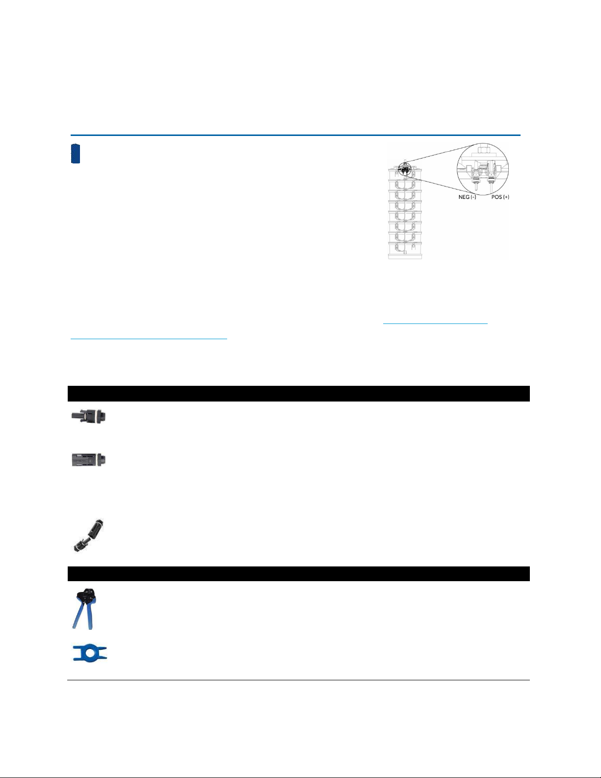
6.1.1 Stack Connectors
The connectors, found at the top of the battery stack, are as follows:
−Negative (Black): Female Amphenol Helios H4 Connector
(H4CFC4DI)
+Positive (Red): Male Amphenol Helios H4 Connector (H4CMC4DI)
6.1.2 Stack Accessories
The following standard solar connectors and tools are required to make connections to the S30-0080
battery stack. Aquion Energy does not supply these parts. They can be purchased through Amphenol
distributors worldwide. Find your nearest authorized distributor here: http://www.amphenol-
sine.com/Distributors_c_108.html.
Image Part Name
Optional,
Recommended,
Required Purpose Part Number Manufacturer
Quantity per
Battery Stack
Connectors
H4 PV Panel
Connector,
Male
Required Connection to
positive battery
stack terminal
H4CMC4DI Amphenol
SineCo
1
H4 PV Panel
Connector,
Female
Required Connection to
negative battery
stack terminal
H4CFC4DI Amphenol
SineCo
1
-------------------------------------------------------- OR -------------------------------------------------------
H4 PV Panel
Connector,
Mated Pair
Optional Connection to
negative and
positive battery
stack terminals
H4CPC4DI Amphenol
SineCo
1
Tools
Helios H4
Panel
Connector
crimpers
Required Attach H4 Panel
Connectors to
cable
H4TC0001 Amphenol
Industrial
NA
H4 Universal
Unlocking
Tool
Recommended Releases H4 Panel
Connectors from
cable
H4TU0000 Amphenol
Industrial
NA
12 AQ-OP-00016_C
M-Line Battery Module
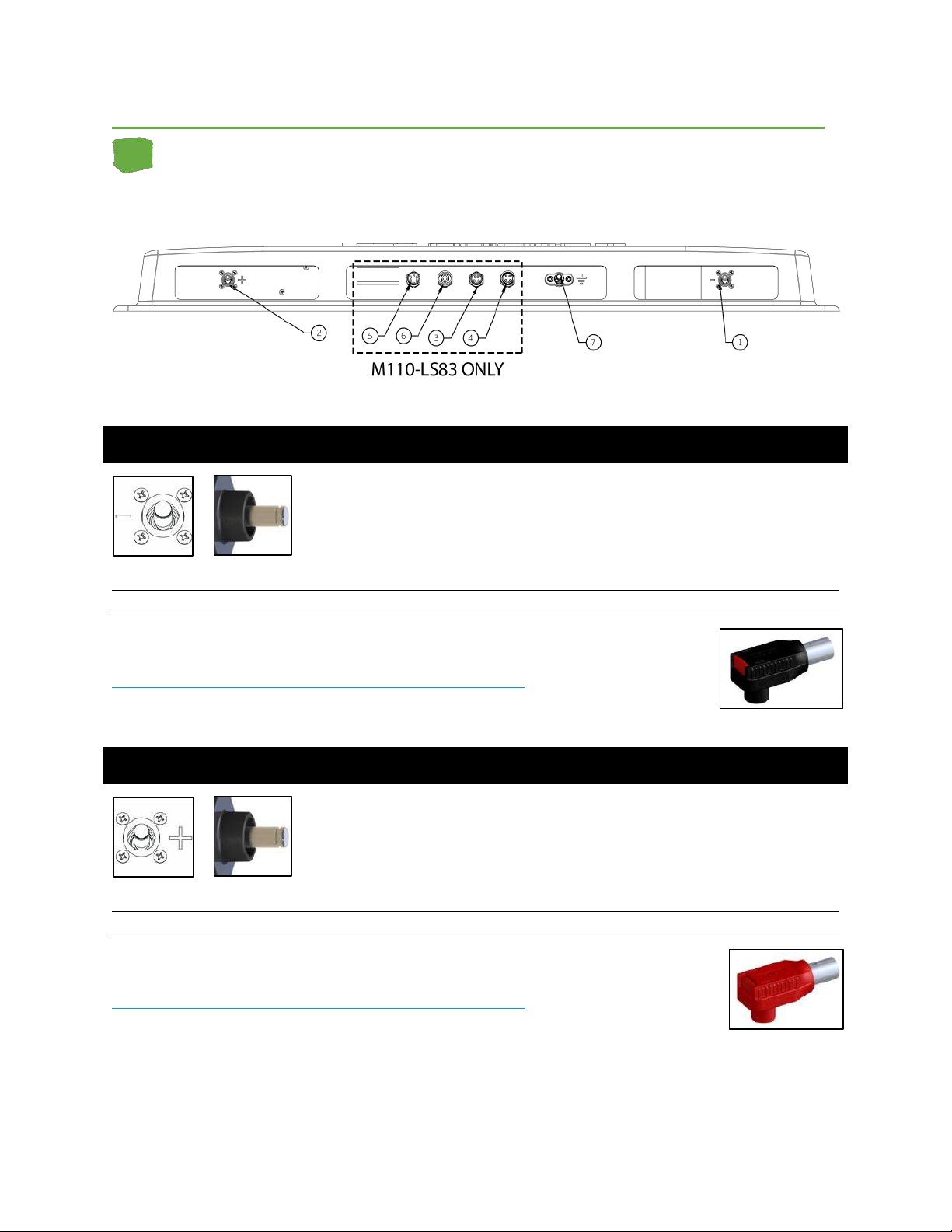
6.1.3 Module Connectors
①Module Negative (-) Battery Terminal
Function:
Negative termination of battery module
Part:
Amphenol RADLOK RL9-100-101 Black
Pin # Name Wire Color Description
1 BATT- Black Module Battery Negative Terminal
Mating connector:
Amphenol RADLOK Tubular Connector Black RL0-100-1-xxBK
Part not supplied by Aquion. Find your nearest authorized Amphenol distributor at
http://www.amphenol-sine.com/Distributors_c_108.html. In the part number, xx
refers to cable size, which is determined by your installation.
②Module Positive (+) Battery Terminal
Function:
Positive termination of battery module
Part:
Amphenol RADLOK RL9-100-101 Red
Pin # Name Wire Color Description
1 BATT+ Red Module Battery Positive Terminal
Mating connector:
Amphenol RADLOK Tubular Connector Red RL0-100-1-xxRE
Part not supplied by Aquion. Find your nearest authorized Amphenol distributor at
http://www.amphenol-sine.com/Distributors_c_108.html. In the part number, xx
refers to c1able size, which is determined by your installation.

13 AQ-OP-00016_C
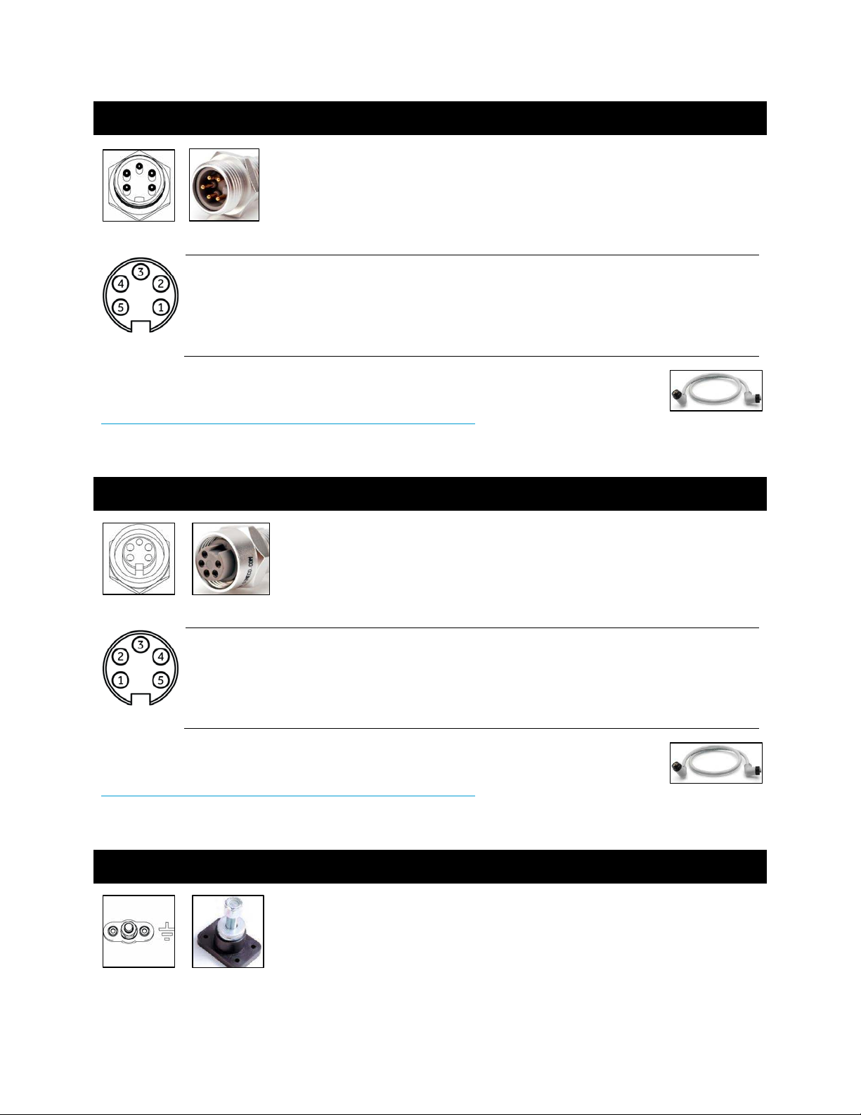
③24V I/O IN
Function: Power input for contactor control
Part:
Amphenol SineCo MN41PW02Mxxx 4-pin miniBOSS, Male
Receptacle, External Threads
Pin # Name Wire Color Description
1 24V_IO_NEG Black 24 V I/O Negative
2 24V_IO_POS White 24 V I/O Positive (for driving contactors)
3 INTLK_RLY_IN Red Interlock Relay In (normally open)
4 RLY_RTN_IN Green Interlock Relay Return In
Mating connector:
Amphenol SineCo MN47B4BC01Mxxx 4-pin miniBOSS Cordset
Part not supplied by Aquion. Find your nearest authorized Amphenol distributor at
http://www.amphenol-sine.com/Distributors_c_108.html. In the part number, xxx
refers to cable length, which is determined by your installation.
④24V I/O OUT
Function: Power output for contactor control
Part:
Amphenol SineCo MN44PW02Mxxx 4-pin miniBOSS, Female
Receptacle, Internal Threads
Pin # Name Wire Color Description
1 24V_IO_NEG Black 24 V I/O Negative
2 24V_IO_POS White 24 V I/O Positive (for driving contactors)
3 INTLK_RLY_IN Red Interlock Relay In (normally open)
4 RLY_RTN_IN Green Interlock Relay Return In
Mating connector:
Amphenol SineCo MN47B4BC01Mxxx 4-pin miniBOSS Cordset
Part not supplied by Aquion. Find your nearest authorized Amphenol distributor at
http://www.amphenol-sine.com/Distributors_c_108.html. In the part number, xxx
refers to cable length, which is determined by your installation.
14 AQ-OP-00016_C
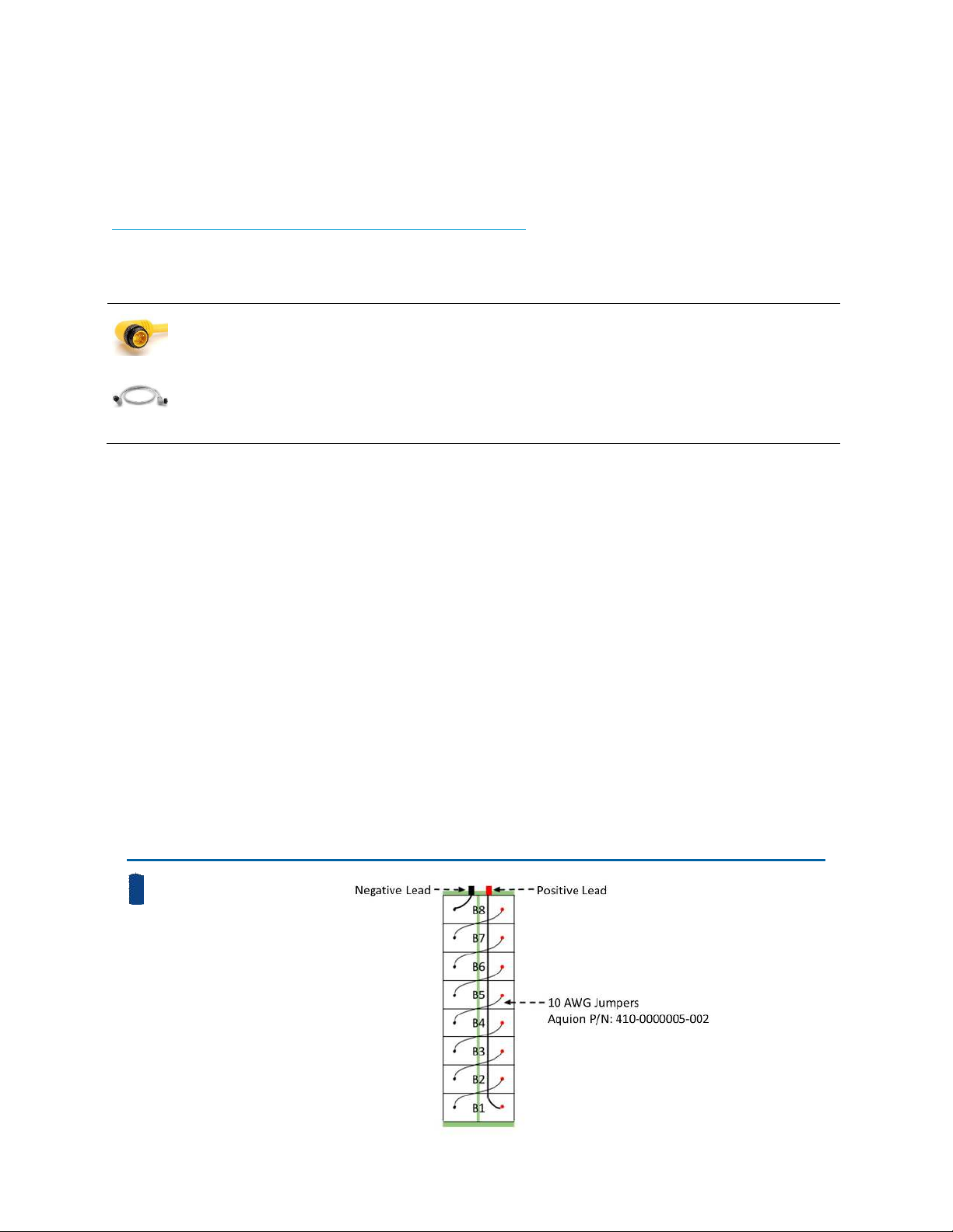
⑤CAN IN
Function: Input for sensing board power and CANbus communication
Part:
Amphenol SineCo DeviceNet MN51PD01M005 Male Receptacle,
External Threads
Pin # Name Wire Color Description
1 CAN_GND Bare Isolated CAN Ground
2 24V_LOGIC_POS Red 24 V Logic Positive
3 24V_LOGIC_NEG Black 24 V Logic Negative
4 CAN_H White CAN High Signal
5 CAN_L Blue CAN Low Signal
Mating connector:
Amphenol SineCo DeviceNet Thick MN57B4BD01Mxxx Patch Cable
Part not supplied by Aquion. Find your nearest authorized Amphenol distributor at
http://www.amphenol-sine.com/Distributors_c_108.html. In the part number, xxx
refers to cable length, which is determined by your installation.
⑥CAN OUT
Function:
Output for sensing board power and CANbus communication
Part:
Amphenol SineCo DeviceNet MN54PD01M005 Female Receptacle,
Internal Threads
Pin # Name Wire Color Description
1 CAN_GND Bare Isolated CAN Ground
2 24V_LOGIC_POS Red 24 V Logic Positive
3 24V_LOGIC_NEG Black 24 V Logic Negative
4 CAN_H White CAN High Signal
5 CAN_L Blue CAN Low Signal
Mating connector:
Amphenol SineCo DeviceNet Thick MN57B4BD01Mxxx Patch Cable
Part not supplied by Aquion. Find your nearest authorized Amphenol distributor at
http://www.amphenol-sine.com/Distributors_c_108.html. In the part number, xxx
refers to cable length, which is determined by your installation.
⑦EARTH GROUND LUG
Function:
Battery module grounding
Part:
Cooper Bussmann C1938
Mating connector:
Ground wire with 3/8" ring terminal
Parts not supplied by Aquion.
15 AQ-OP-00016_C
6.1.4 Module Accessories
The following power and communication cables are required to make connections to the M110-LS83
and M100-L083 battery modules. Aquion Energy does not supply these parts. They can be purchased
through Amphenol distributors worldwide. Find your nearest authorized distributor here:
http://www.amphenol-sine.com/Distributors_c_108.html.
Image Part Name
Optional,
Recommended,
Required Purpose Part Number Manufacturer
Quantity
per Module
4-pin
miniBOSS
Cordset
Required for
M100-LS83
Provides 24 V to power
the coil in the safety
contactor
MN47B4BC01Mxxx Amphenol
SineCo
1
DeviceNet
Thick Patch
Cable
Required for
M100-LS83
CANbus connection
between sensed modules
and BMS-200
MN57B4BD01Mxxx Amphenol
SineCo
1
6.1.5 Module Contactor Control
A DC contactor is installed on the positive (+) lead of each battery module. The DC contactor
must be powered by an external 24 V power supply. Aquion does not provide this power supply.
Each DC contactor power supply must be capable of supplying 100 mA times the number of
modules in the system, plus up to 1 A of surge current. The DC contactor operation can be easily
integrated into a system-level emergency stop (ESTOP) system to break down the series voltage
to <57.6 Vdc.
For systems equipped with an Aquion Battery Monitoring System (BMS), the DC contactor can be
commanded open by the BMS if certain alarm limits are exceeded. However, there will be a
1-second (adjustable) warning signal sent by both hardware and software before the module
contactor is opened. The hardware signal is a dry contact signal on the module 4-pin 24 V
connector that can be sensed by the site controller. The software signal is a Modbus command
sent from the BMS to the site controller.
6.2 Product Wiring Diagrams
S-Line Battery Stack
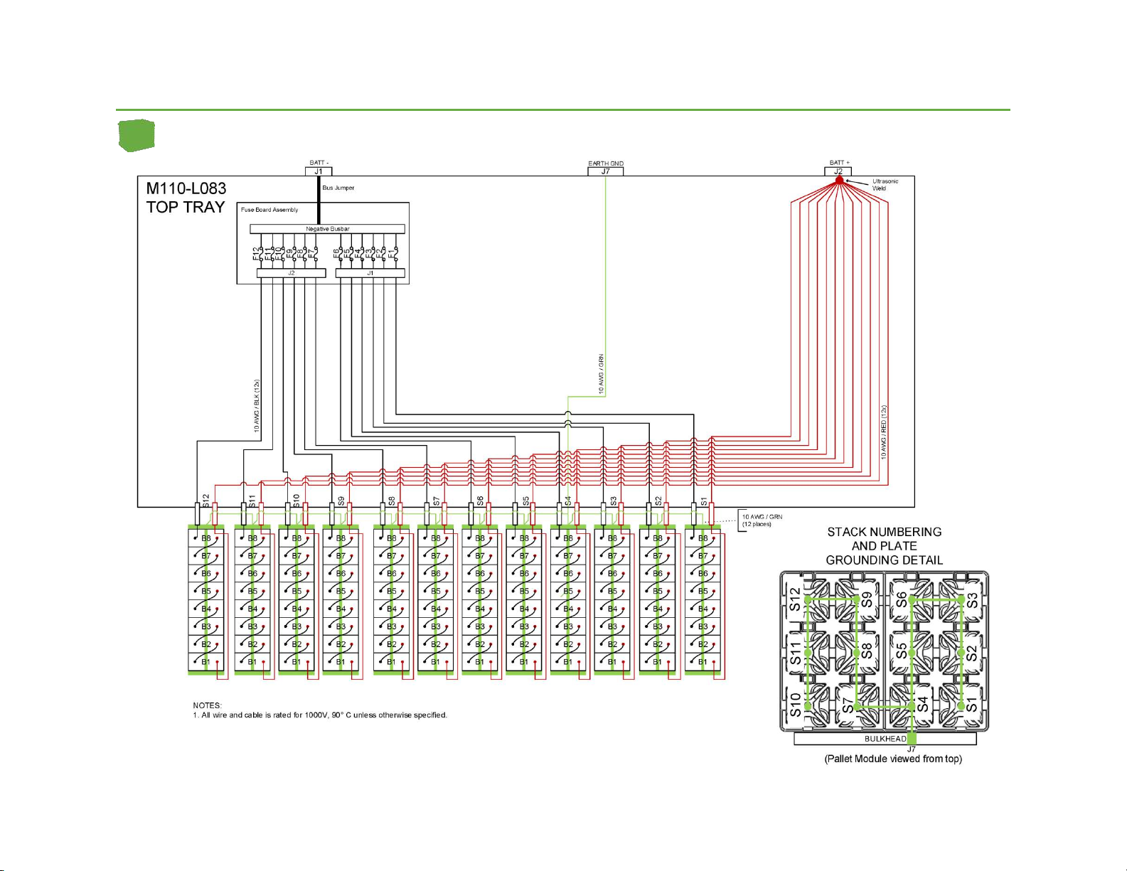
16 AQ-OP-00016_C
M-Line Battery Module
This manual suits for next models
4
Table of contents
Other Aquion Energy Camera Accessories manuals


