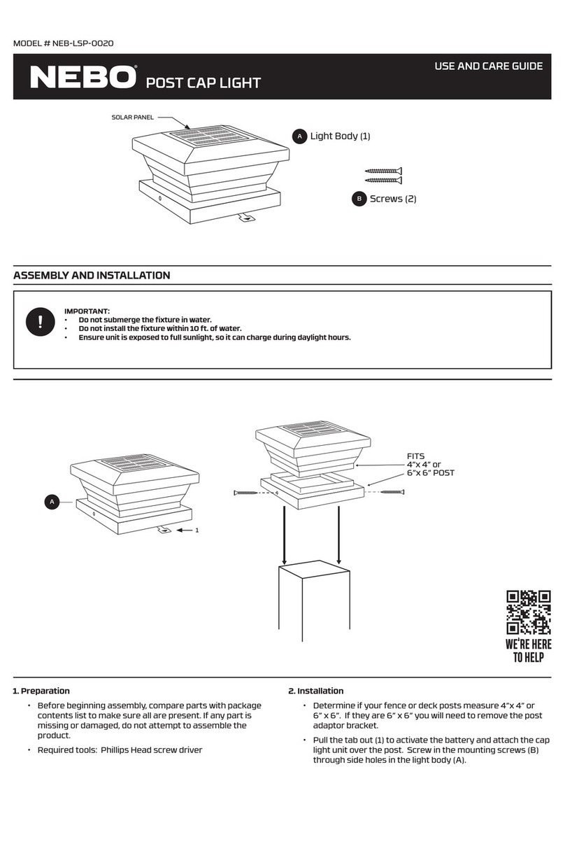
Nightscaping Mailbox Series Assembly instructions

Locate the area where the Mailbox will be placed.
If the Bollard is not being mounted to existing concrete
or a permanent surface then a footer is needed.
Dig a hole for the footer. Refer to the Table A below for
suggested footing size.
BOLLARD SIZE RECOMMENDED FOOTER
Estate Series - 6x6x42”
Table A
Place the 1/2” electrical conduit (shown in Figure B) into the
footer. The top of the electrical conduit should be sitting at least
1” above the top of the footer hole/ground level. The base of
the electrical conduit should exit into the ground. If using J-Bolts
flip to Page 2 now.
Pour concrete around the 1/2” electrical conduit, filling the
footer. DO NOT FILL THE ELECTRICAL CONDUIT WITH CONCRETE.
Ensure that the concrete footer is level by using a Torpedo level.
Allow the concrete to cure for the recommended time
specified by the manufacturer.
Once the concrete has cured, position the Universal Mounting
Plate (UMP) onto the concrete footer in the desired position.
Mark your pilot holes for the wedge anchor bolts (provided). If
using J-bolts please see J-bolt installation instructions (Page 2).
1.
2.
3.
4.
5.
6.
Concrete Footer
Bollard Tube
Base Plate
Cover
1/2” Electrical Conduit
Universal Mounting
Plate
Figure B
25’ Lead
Wire
Using a carbide tipped 3/8” drill bit (sold seperately), drill pilot
holes in the marked locations. After the pilot holes have been
drilled, insert the wedge anchor bolts (use hammer to secure).
7.
Place the UMP over the anchor bolts. Once it is located in the
desired position tighten the nuts until the UMP is securely
fastened to the footer. Make sure to raise the Bollard about
1/2” above the ground level using the provided nuts and bolts.
Not following these instructions will void all warranties.
8.
Run the lead wire from the luminaire through the 1/2” electrical
conduit and connect it to the power supply line using lithium
grease filled wire nuts.
9.
Place the Base Cover Plate over the Bollard then slide the
Bollard over the UMP (shown in Figure D). Check to make sure
that the Bollard is level and securely fasten the Bollard to the
UMP using the screws provided.
10.
Figure C
Figure D
Install the Mailbox Topper shown in Figure C. See page 4 for
more details on installation of the mailbox and address plate.
11.
24” Service
Wire Lead
10” Diameter x 30” Deep
Mailbox Bollard Installation Sheet
CorTen Steel Mailbox Bollard Light
Mailbox Series Bollards
Mailbox Installation Instructions:
D
42”
30”
C
®
HANDCRAFTED IN THE USA SINCE 1959

Mailbox Bollard Installation Sheet
CorTen Steel Mailbox Bollard Light
Mailbox Series Bollards
®
HANDCRAFTED IN THE USA SINCE 1959
Mailbox Installation Instructions: Footer/Concrete J-Bolt Mount Option - PART ONE
F
Refer to Table A for Proper
Footer Size/Depth
8”x24” Concrete
Footer Shown
10” Forming Tube
J-Bolts
(Sold Separately)
Washers
Nut
Plywood/Cardboard
Template -
Ensure Template
Is Level
1/2” Electrical
Conduit (90˚ Elbow)
Nut Secures Template
(Stays in Concrete)
MAKE SURE TO TAPE UP
BOTH ENDS OF THE CONDUIT
WITH DUCT TAPE TO ENSURE
NO CONCRETE ENTERS
Concrete Surface
Figure F
E
Figure E
Plywood/Cardboard
Template
Soil Level Must Stay
1/2” Below Concrete
Warranty is Voided if
Soil Covers the Base
of the Bollard
STEP ONE CREATE A TEMPLATE
STEP TWO PLACE TEMPLATE WITH J-BOLT ASSEMBLEY INTO FOOTER WITH WET CONCRETE
Plywood/Cardboard Template
for Anchor Bolts
Cut 4 1/2”Holes for
the J-Bolts
6x6x42 Bollard
MAILBOX BOLLARD TEMPLATE
Cut 5/8”Hole In The
Center of the Template for
Electrical Conduit
3.359”
3.359”
BOLLARD SIZE RECOMMENDED FOOTER
Estate Series - 6x6x42”
Table A
10” Diameter x 30” Deep

Mailbox Bollard Installation Sheet
CorTen Steel Mailbox Bollard Light
Mailbox Series Bollards
Mailbox Installation Instructions: Footer/Concrete J-Bolt Mount Option - PART TWO
STEP THREE REMOVE THE TEMPLATE
®
HANDCRAFTED IN THE USA SINCE 1959
Refer to Table A for Proper
Footer Size/Depth
8”x24” Concrete
Footer Shown
10” Forming Tube
J-Bolts
(Sold Seperately)
Nut & Washer Assembly
1/2” Electrical
Conduit (90˚ Elbow)
Concrete Surface
Figure H
G
UMP for 6x6x42”
Mailbox Bollard Shown
Above In Figure G
H
Universal Mounting
Plate Fastens Tightly
to Concrete Surface
Universal Mounting
Plate Fastens Tightly
to J-Bolts with Nuts
and Washers Provided
Suggestion: To Hide
Concrete Footer
Use Mulch or
Ground Cover
G
FULLY CURED
CONCRETE FOOTER
Soil Level Must Stay
1/2” Below Concrete
Warranty is Voided if
Soil Covers the Base
of the Bollard
Remove the Template once the concrete has cured completely and replace it with
the Nightscaping Universal Mounting Plate (UMP) shown below in Figure G and G .
1
1
2
STEP FOUR SECURE THE UMP TO THE J-BOLTS
Once you have placed the UMP onto the four J-Bolts, use the nuts and washers provided in your installation kit to secure
the UMP to the concrete footer. Now that the UMP is securely fastened to the concrete footer, slide the bollard tube and
base cap over the UMP and securely fasten the Nightscaping 6x6x42” bollard to the UMP.
2
2
Nut & Washer Assembly

Once you have secured the bollard tube to the UMP
(Shown in Figure K); now it is time to attach your
Mailbox Topper and optional Address Plate.
Remove the Mailbox Topper (and Address Plate) from
the protective packaging.
Place the Mailbox Topper on top of the 6x6x42”
bollard tube - Shown below in Figure I. Securely fasten
the Mailbox Topper with the four stainless steel screws
(provided) to the top of the bollard tube.
If attaching an Address Plate to the Bollard, attach the two
stainless steel screws (provided) to the top part of the Mailbox
Topper’s mounting plates. The two screws fasten directly to the
Mailbox Topper’s mounting plates. Mounting Plate shown in
Figure I.
After securely fastening the two top screws on the Address
Plate to the Mailbox Topper’s mounting plate use a drill to
attach the base of the Address Plate to the Bollard Tube using
the stainless steel self-tapping screw provided - Shown in
Figure J. Drill a small pilot hole before inserting the self-
tapping screw (This step is recommended - but not required).
After securely fastening the Address Plate to the Bollard Tube
your installation process is complete!
1.
2.
3.
4.
5.
6.
Concrete Footer
Bollard Tube
Base Plate
Cover
1/2” Electrical Conduit
Universal Mounting
Plate
Figure K
25’ Lead
Wire
Figure I
Figure J
24” Service
Wire Lead
6x6x42”
Bollard Tube
Mailbox Topper
Mailbox Bollard Installation Sheet
CorTen Steel Mailbox Bollard Light
Mailbox Series Bollards
Mailbox Installation Instructions:
J
42”
30”
I
Mounting Plate
On Mailbox Topper
Address Plate
®
HANDCRAFTED IN THE USA SINCE 1959
This manual suits for next models
1
