Niko KM 70 User manual

NIKO GmbH Maschinen- & Fahrzeugbau . Im Mühlgut 1a . D-77815 Bühl-Weitenung
Operation Manual
Combination Mulcher
Model KM 70 / 85 / 100
Compatible with HP 510; HY 20-22/11; HY 30-38/16;
HY38/16A; HY 38-40/2008

NIKO GmbH Maschinen- & Fahrzeugbau . Im Mühlgut 1a . D-77815 Bühl-Weitenung
Introduction
Dear Customer,
Thank you for the trust in us you have demonstrated by purchasing a NIKO product. We would like to assure
that we have done everything possible to provide you with an efficient and reliable product.
Please read this operation manual carefully before operating the machine and note the instructions and
warnings. The operation manual will fully explain the operation of the machine and give you valuable
information regarding maintenance and care.
This is important, as warranty replacement claims cannot be recognized for damages caused by operator
error or improper use.
When ordering replacement parts, retrofitted accessories or when making complaints, please also provide
the model and type of your device, as well as its equipment. You can find detailed information regarding this
on the device label which is attached to this operation manual.
Model: Combination Mulcher KM 70 / 85 / 100
Installable on Small Bulldozers: HP 510; HY 20-22/11; HY 30-38/16 HY38/16A and HY 38-40/2008
Technical Improvements:
We endeavor to constantly improve NIKO products. We therefore reserve the right to undertake all
improvements and changes which we deem necessary for our equipment without prior notification without,
however, obligating ourselves to conduct these improvements or changes to machines already sold.
We are happy to answer any question you may have and wish a pleasant experience with your new NIKO
product.
With best wishes,
N I K O
Maschinen- & Fahrzeugbau
Dieter Serr, Chief Executive

1
Table of Contents
•Product Description
1.) Designated Use
2.) Setup
3.) Function Description
4.) Technical Information
5.) EU Declaration of Conformity
•General Safety Instructions
1.) Operator’s Obligation to Exercise Diligence
2.) Explanation of the Symbols Used
3.) Basic Safety Measures
4.) Requirements of the Operating Personnel
5.) Special Types of Danger
•Transportation
•Troubleshooting
•Repairs / Maintenance
•Replacement Part Lists
•Warranty Conditions
•Device Label

ADDITIONAL
INFORMATION
2
Product Description
The NIKO Combination Mulcher KM is used in winemaking and forestry to mulch grass and wood cuttings
and in municipal areas for hedge cutting and trimming undergrowth. The device is very robust and can be
used for various purposes.
1. Designated Use
The combination mulcher is exclusively designated for:
-The mulching of grass and wood cuttings
The machine is not designated for other types of uses – these will be deemed to be improper uses! We
expressly indicate that large pieces of wood, stones and other similar objects be removed from the
work area.
2. Setup
3
-
Point Intake
Lifting Cylinder Intake
Fan Belt
Tensioner
Lubrication
Nipple
Lubrication
Nipple
Air Filter
Starter Flap
Gas Valve
Stop Button
Oil Dipstick
Axial Piston Oil Motor Parker F11
Product Nr.: 22488

ADDITIONAL
INFORMATION
3
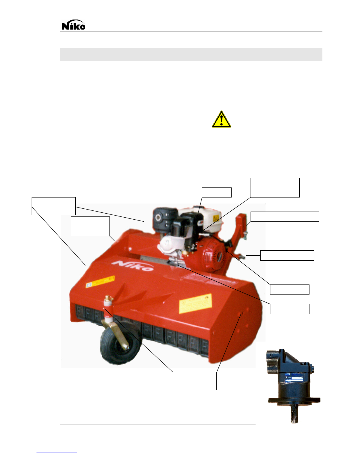
3. Function Description
Attachment to the basic device takes place via the 3-point intake with two quick locks and a bolt on the
hydraulic cylinder for lifting the device. The throttle is attached to the space provided on the handlebars of the
bulldozer. In doing so, it must be ensure that the Bowden cable is not bent or jammed.
The cutting quality of the combination mulcher mounted on the bulldozer is dependent upon the travelling
speed, the height and density of the object being cut as well as the condition of the cutting tools. Dependent
upon the conditions of these parameters, the working speed amounts to approximately 4 -6 km/h and
approximately 2 -4 km/h for the cutting of wood.
In order to work with the mulching device, the gasoline motor/oil motor will be started in accordance with the
directions in the motor manual provided.
Gasoline Motor:Fill with normal gasoline
Check the oil level
Open the gas valve
Set throttle to “fully open"
Closer the start flap [only if the motor is cold]
Pull out starter until resistance can be felt
Start the motor with a short, strong jerk.
Slowly close the starter flap.
Oil Motor: The oil motor is turned on using the 3-way valve.
WARNING: Only start the 3-way valve when the device is running!!!
Check the hydraulic hoses to be sure they are tightly sealed
Do not leave the oil motor standing in direct sunlight when decoupling!!!
WARNING:
No objects can be located under the mulcher while it is being started
(Stones, wood, et cetera).
Stand to the side of the device when starting it. Keep a sufficient distance away
and be particularly sure that your feet are not underneath the mower housing.
The cutting height can be adjusted via the undercarriage disc on the guide wheel of the mulcher (never do so
while the motor is running!!!).
To mulch grass, the teeth behind the mower housing must be removed (maximum grass throughput).
The mulching device is lifted using the hydraulic device hoisting when entering and exiting the vineyard or to
turn. While mowing, the device is operated in floating position (movable via the long hole in the device
hoisting). When driving up steep inclines, the mulcher cannot be completely lifted as this could allow motor oil
to enter the combustion chamber and cause the motor to stop via the oil warning switch.
When driving on paths, while turning, et cetera, the motor speed is to be reduced to idling using the throttle in
order to bring the cutter shaft driven via the centrifugal clutch.
Inspect the area for objects and obstacles hidden in the grass
and remove these prior to mowing.
While mowing, always operate at full throttle in order to prevent the sliding of the centrifugal clutch and
ensure sufficient traction.
- To turn off the gasoline motor, first reduce the speed to idling and then turn off the motor using the short
circuit switch.
The gasoline valve should remain closed while the mulcher is being transported.
- Close the 3-way valve to turn off the oil motor.

ADDITIONAL
INFORMATION
4
4. Technical Information
Combination Mulcher 70
Combination Mulcher 85
Combination Mulcher 100
Working Width
0.70 m
0.85 m
1.00 m
Device Width
0.82 m
0.97 m
1.12 m
Length:
1.25/1.45 m
1.25/1.45 m
1.25/1.45 m
Height:
0.80 m
0.80 m
(0.90 m with large tank)
0.80 m
(0.90 m with large tank)
Weight:
105 kg
110 kg
115 kg
Cutting Elements:
36 Pieces
48 Pieces
56 Pieces
Engine:
9 PS Gasoline Motor
Honda GX 270;
Oil Motor Parker F11
13 PS Gasoline Motor
Honda GX 390;
Oil Motor Parker F11
13 PS Gasoline Motor
Honda GX 390;
Oil Motor Parker F11
EU Declaration of Conformity
As per Appendix II A of the EC Machinery Directive (89/392/EWC)
The Manufacturer: NIKO Maschinen- & Fahrzeugbau
Im Mühlgut 1
D-77815 Bühl-Weitenung Germany
Hereby declares that the machine described in
the following:
Kombimulcher Typ 70/85/100
Meets the safety and health requirements of the
following EU Directives:
EU Machinery Directive 89/392/EWC in the Version
93/44/EWC
Applied Harmonized Norms:
DIN EN 292
Section 1
Section 2
DIN EN 294
DIN EN 349
DIN EN 418
DIN EN 60204
Section 1
Safety of Machines:
Basic Terms, General Design Principles
Technical Principles and Specifications
Safety Distance to Prevent Danger to the Upper Extremities
Minimum Distances to Avoid Crushing of Body Parts
Safety of Machines; Emergency Shut Down Device
Safety of Machines; Electrical Equipment of Machines,
General Requirements
Structural changes which affect the technical information and designated use listed in the operation manual
and thus essentially alter the machine invalidate this declaration of conformity!
Bühl, March 10, 2008 Dieter Serr, Chief Executive

ADDITIONAL
INFORMATION
5
General Safety Instructions
1. Operator’s Obligation to Exercise Diligence
The Combination Mulcher was designed and constructed under consideration of a risk analysis and after
careful selection of the harmonized norms to be maintained, as well as additional technical specifications.
It is state of the art and guarantees a high measure of safety.
This safety, however, can only be reached during operational use when all measures required for it are met.
The planning of these measures and the examination of their execution falls under the operator’s obligation
to exercise diligence.
The operator must especially ensure that:
-The machine may only be used for its designated purpose (see Production Description section)
-The machine can only be operated in faultless, fully functional condition and the safety devices must
especially have their functionality regularly inspected
-The required personal protective equipment for the operating, maintenance and repair personnel must be
available and be used
-The operation manual must always be available in a complete and readable condition at the location
where the machine is used
-Only sufficiently qualified and authorized personnel may operate, maintain and repair the machine and
who are familiar with the operation manual and particularly the safety instructions located within it.
-All safety and warning notices placed on the machine are not removed and remain legible
2. Explanation of the Symbols Used
The following safety symbols are used in this operation manual. The symbols should, above all, make the
reader aware of the safety instructions written alongside the text.
This symbol indicates that danger to the life and health of persons, machines, materials or the environment
exists.

ADDITIONAL
INFORMATION
6
3. Basic Safety Measures
Safety Measures for the NIKO Combination Mulcher
Protective equipment provided by the manufacturer may not be removed.
Repairs and the replacement of parts may only be conducted when the motor is turned off.
Only allow repairs to be conducted by your retailer.
4. Requirements of the Operating Personnel
The motorized device may only be operated by adults in full possession of their physical and mental faculties.
Persons under the influence of alcohol, drugs or medications are to be prohibited from operating of the
machine.
5. Special Types of Danger
If injuries occur, consult a doctor immediately.
It is urgently necessary to ensure that the blades of the combination mulcher are sufficiently attached.
Defective parts as well as deformed blades should be replaced immediately. Use only original blades.
Check the functionality of the bolts and safety screws, as well as the 3-point lock.
Regularly inspect the hydraulic conduits.
The rotating cutter shaft must be inspected for damage and the complete number of blade after each usage.
Transportation
In order to avoid damage to the machine or life threatening injuries while transporting the machine, the
following items must absolutely be adhered to:
-Transportation may only be conducted by qualified personnel under compliance with the safety
instructions.
-The machine may only be lifted using the suspension points provided.
-The machine should only be transported with the bulldozer; if this is not possible the machine can be
moved on a palette with a forklift.
-Always close the gas valve when transporting the mulcher.

ADDITIONAL
INFORMATION
7
Troubleshooting
In order to avoid damage to the machine or life threatening injuries while remedying malfunctions in the
machine, the following items must absolutely be adhered to:
-Only repair a malfunction if you have the required qualifications to do so.
-First secure the machine against unintentionally being turned back on by removing the spark plug
terminal.
-Use a second person to guarantee an emergency shutdown of the machine at all times.
-Secure the area used by moving parts of the machine.
-Please also read the “General Safety Instructions” section.
Overview of Possible Malfunction Notifications and Help in Remedying
Them in Table Form
Cause Response
Gasoline motor does not turn on
- Refill fuel
- Set shut off switch to on
- Oil level too low (refill)
- Check sparkplug (replace)
Mulcher does not work
- Check gasoline motor (sparkplug, air filter, et
cetera)
- Check fan belt tensioner and tighten if necessary
Mulcher vibrates
Imbalance in the cutter shaft (missing or unequally
worn blades)
Unclean cutting
- Replace missing or worn blades
- Tighten fan belt
- Motor speed insufficient
- Centrifugal clutch is grinding (Pads worn, motor
speed too slow)
- Speed too fast
- Growth too high (reduce speed)

ADDITIONAL
INFORMATION
8
Maintenance
In order to avoid damage to the machine or life threatening injuries while servicing the machine, the following
items must absolutely be adhered to:
-First ensure a spacious area for the maintenance work.
-Use only original replacement parts which are listed on our replacement parts lists.
1. Cleaning and Lubrication
After Each Usage
-Clean and re-lubricate all moving parts
-Check mulcher blades for completeness and wear
(In order to avoid imbalances, please always replace the complete set)
Daily
-Check the oil level
-Clean the air filter (replace if necessary)
Every 15 Operating Hours
-Check the fan belt tension (!! Warning !! never loosen the upper bearing to tighten the fan belt)
-Lubricate the cutter shaft (lubrication nipple)
-Lubricate the drive shaft (lubrication nipple)
Every 30 Operating Hours
-Lubricate the guide wheel (lubrication nipple)
Replace oil, oil filter and air filter in accordance with the motor manual

ADDITIONAL
INFORMATION
9
Combination Mulcher KM 70 / 85 / 100
17101 Rubber Cover
17132 Tension Element
17102 Bearing with Adjustment Ring UCF 208
17133 Teflon Disc
17102a
Bearing EN-208D1
17134 Tightening Handle
17103 Hexagonal Screw M14*40
17135 Complete Housing
17104 Fan Belt Disc
17136 Hexagonal Screw M14*40
17105 Wedge
17137 Spacer
17106 Spacing Pipe
17138 Axle
17107 Washer
17139 Rubber Wheel
17108 Hexagonal Screw M16*35
17140 Splint
17109 Throttle (new design) see illustration
17141 Roller Bearing
17110 Accelerator Cable (new design) see illustration
17142 Washer Drm. 25
17111 Retaining Plate
17143 Wheel Clamp
17112 Complete Motor Model 11 PS
17144 Fan Belt Cover
17112a
Complete Motor Model 13 PS
17145 Y Blade (1 Piece) see illustration
17113 Stud M8*20
17145a
Curved Blade, old design
17114 Drive Shaft
17145b
Y Blade, Fischer Model
17115 Bearing UCF 206
17145c
LS Hammer Blade 63-RM-32 (1 pair)
17116 Stopping Nut M12
17145d
Blade FR275 (1 pair = 2 pieces)
17117 Hexagonal Screw M12*40
17145e
Blade M225 (2 pieces)
17118 Fan Belt KM 85/100 NEW 17*1203 (Gas Engine)
17145f
Y Blade 63-FEI-04
17118a
Fan Belt KM 85 OLD 13*1550
17146 Hexagonal Screw M12*60 (C9)
17118b
Fan Belt 17*940
17147 Clamp
17118c
Fan Belt KM 130 17*1040
17148 Stopping Nut M12
17118d
Fan Belt BX 17*1160 LP
17149 Complete Cutter Shaft
17118e
Fan Belt 17*1130 (Hydraulic Drive)
17150 Drive Shaft Covering
17119 Centrifugal Clutch
17151 Hexagonal Screw M10*15
17120 Wedge
17152 Tooth Lock Washer Drm. 10.5
17121 Washer
17153 Washer Drm. 10.5
17122 Countersunk Bolt M8*20
17154 Mulcher Blade M175
17123 Complete Left Bearing Block
17155 Blade Holder
17124 Complete Right Bearing Block
17156 Socket 25*16*12
17125 Fan Belt Tensioner
17157 Screw M16*50
17126 Bearing 6001
17158 1048 Cutter Shaft
17127 Snap Ring Drm. 28
17159 Castle Nut M20
17128 Snap Ring Drm. 16
17160 Square Key 10*8*35
17129 Clamping Arm
17161 Square Key 10*8*25
17130 Axle
22488 Oil Motor Parker F11 (see page 2)
Ersatzteilliste
7
6
5
4
1
3
2
10
11
12
13
9
14
15
8
16
46
44
41
43
45
40
42
39
38
37
36
20
17
18
19
21
22
23
24
25
26
27
28
29
30
31
32
33
34
35
49
48
47
50
51
52
53
17145 Flail Blade (Item) Old New
Type 70 22 36
Type 85 26 48
Type 100 30 56

ADDITIONAL
INFORMATION
10
17131 Snap Ring Drm. 10

ADDITIONAL
INFORMATION
11
Warranty Conditions
NIKO products are produced with great care using modern manufacturing methods and are subjected to
numerous inspections.
Therefore, NIKO provides warranties of 12 months if the following conditions are fulfilled:
1.) The warranty begins with the date of the purchase.
2.) The warranty covers material and production defects. We are only liable within the framework of the
warranty of the respective manufacturer for third party products (hydraulics, electronics, motor).
Production and material defects will be remedied by replacement or improvement to the affected parts
free of charge during the warranty period. Other, additional rights, such as claims for conversion,
reduction or rectification of damages which did not to t
he object of the delivery are expressly prohibited.
The warranty services take place exclusively through authorized work centers, the NIKO
production representatives or the factory.
3.) The results of natural wear, debris, corrosion and all error caused by improper use, as well as external
influences, are excepted from the warranty services. The warranty is void in the event of the independent
conducting of repairs or alterations to the original conditions. The replacement part claim is void if NIKO
original replacement parts are not used.
Please carefully read the operation manual. In all cases of doubt, please consult our production
representatives or the factory.
Warranty claims must be asserted to the factory within 30 days after the occurrence of the damage.
Please provide the date of purchase, machine number and motor number. Please use our warranty
application form for this.
Repairs that are to be conducted under the warranty may only be conducted by authorized work centers
after consultation with NIKO, please indicate this to your retailer.
The warranty period does not extend in the event of work covered by the warranty!
Transportation damages are not production errors and are thus not covered by the manufacturer’s
obligation to provide a guarantee.
4.) Claims for the compensation of damages which did not occur to the product itself are prohibited. This
also means that liability for consequential damages due to operator errors is prohibited. Independent
alterations to the product can lead to consequential damages and rule out liability on the part of the
deliverer for these damages.

ADDITIONAL
INFORMATION
12
This manual suits for next models
2
Table of contents