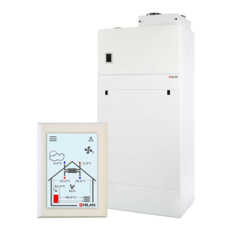
nilan CTS602 HMI User manual

INSTALLATION INSTRUCTIONS
CTS602 HMI BY NILAN
Combi 302 Polar Top (English)
Version 3.01 - 25.03.2019

TABLE OF CONTENTS
Safety
Power supply................................................................................................................................................................................................................................................................... 4
Heat pump ventilation.......................................................................................................................................................................................................................................... 4
Disposal............................................................................................................................................................................................................................................................................................. 4
Ventilation unit............................................................................................................................................................................................................................................................. 4
Heatpump .......................................................................................................................................................................................................................................................................... 4
General information
Introduction.................................................................................................................................................................................................................................................................................. 5
General information prior to installation.........................................................................................................................................................................................5
Final inspection......................................................................................................................................................................................................................................................................... 6
Ventilation Combi unit.......................................................................................................................................................................................................................................... 6
Unit type........................................................................................................................................................................................................................................................................................... 7
Product description ................................................................................................................................................................................................................................................ 7
Overview of temperature sensors..........................................................................................................................................................................................................8
Dimensional drawing.............................................................................................................................................................................................................................................. 9
Functional diagram............................................................................................................................................................................................................................................... 10
Accessories................................................................................................................................................................................................................................................................................11
CO2 sensor..................................................................................................................................................................................................................................................................... 11
EM-box................................................................................................................................................................................................................................................................................ 11
Electrical after-heating element........................................................................................................................................................................................................... 11
Pollen filter.....................................................................................................................................................................................................................................................................11
Water trap....................................................................................................................................................................................................................................................................... 11
Vibration absorbers.............................................................................................................................................................................................................................................12
Flexible sound damper...................................................................................................................................................................................................................................... 12
Set up
Installation..................................................................................................................................................................................................................................................................................13
Positioning of the unit........................................................................................................................................................................................................................................13
Top unit.............................................................................................................................................................................................................................................................................. 13
Electrical installation
Electrical connections....................................................................................................................................................................................................................................................14
Safety.................................................................................................................................................................................................................................................................................. 14
Connection points...................................................................................................................................................................................................................................................14
Control panel............................................................................................................................................................................................................................................................................15
HMI User panel........................................................................................................................................................................................................................................................... 15
Wall bracket.................................................................................................................................................................................................................................................................. 16
Connecting the control panel.....................................................................................................................................................................................................................16
Electrical connections unit....................................................................................................................................................................................................................................... 17
Power supply................................................................................................................................................................................................................................................................17
Unit..........................................................................................................................................................................................................................................................................................17
Electrical connection accessories.................................................................................................................................................................................................................... 18
Connection to user selection and Modbus.................................................................................................................................................................................. 18
Electrical after-heating element........................................................................................................................................................................................................... 19
External heating control system .......................................................................................................................................................................................................... 20
Plumbing installation
Condensate drain................................................................................................................................................................................................................................................................21
Important information...................................................................................................................................................................................................................................... 21
Connection bottom............................................................................................................................................................................................................................................... 22
Plumbing connection - accessories.................................................................................................................................................................................................................23
Water trap with ball (option).......................................................................................................................................................................................................................23
2

Ventilation installation
Duct system.............................................................................................................................................................................................................................................................................. 24
Legislation...................................................................................................................................................................................................................................................................... 24
Ducts..................................................................................................................................................................................................................................................................................... 24
Unit..........................................................................................................................................................................................................................................................................................24
Extract air........................................................................................................................................................................................................................................................................25
Supply air......................................................................................................................................................................................................................................................................... 25
Roof stacks.................................................................................................................................................................................................................................................................... 25
Balancing...................................................................................................................................................................................................................................................................................... 26
Important information...................................................................................................................................................................................................................................... 26
Balancing spouts......................................................................................................................................................................................................................................................26
Pressure fall diagram......................................................................................................................................................................................................................................... 26
Combi 302 Polar Top (English) BY NILAN
3

Safety
Power supply
CAUTION
Always disconnect the power supply to the unit if an error occurs that cannot be rectified via
the control panel.
CAUTION
If an error occurs on electrically conductive parts of the unit, always contact an authorised
electrician to rectify the error.
CAUTION
Always disconnect the power supply to the unit before opening the unit doors, for instance for
installation, inspection, cleaning and filter change.
Heat pump ventilation
CAUTION
Avoid touching the pipes for the heating system in the heat pump. They can get very hot.
CAUTION
To protect the heat pump from damage, the following safety equipment has been fitted:
• Electronic monitoring of the temperature
The heat pump must undergo appropriate service inspections in compliance with current laws and
regulations. This ensures the unit is maintained adequately in accordance with safety and
environmental requirements.
The responsibility for maintaining the heat pump lies with the owner/user.
Disposal
Ventilation unit
Nilan’s units consist mainly of recyclable materials. They must, therefore, not be
mixed with household waste, but must be delivered to your local recycling center
for disposal.
Heatpump
Concerning disposal of units with heat pumps, it is important to contact the local
authorities for information about correct handling of these. The heatpump
contains the refrigerant R134a, which is harmful to the environment if not
handled correctly.
4

General information
Introduction
General information prior to installation
The following documents are supplied with the unit:
• Installation instructions
• Software instructions
• User manual
• Electrical diagram
Instructions can be downloaded from Nilan’s website: http://www.nilan.dk/en-gb/frontpage/download
If you have questions regarding installation of the unit after having read the instructions, contact your
nearest supplier of Nilan products, who can be found on www.nilan.dk/en-gb/frontpage/download/
dealers.
The purpose of these instructions is to advice the installer on correct installation and maintenance of
the unit.
ATTENTION
The unit must be started up immediately after installation and connection to the duct system.
When a ventilation unit is not in operation, humidity from the rooms may penetrate into the
ducts and create condensation. Condensate water may leak out of the valves and damage
furniture and floors. Condensation may also form inside the unit, which can damage its
electronics and fans.
The unit is delivered fully tested and ready for operation.
Combi 302 Polar Top (English) BY NILAN
5

Final inspection
Ventilation Combi unit
How to set the unit
This list is intended for the installer to get an overview of what settings to use in consultation with the
user or the builder.
Function Settings
Setting of frequency of filter change Days:
What level constitutes basic ventilation Level:
Do you want low flow ventilation at low outdoor temperatures yes/no Level:
At °C:
Do you want low flow ventilation at low air humidity yes/no Level:
Level - low air humidity %
Do you want high flow ventilation at high air humidity yes/no Level:
Set maximum time for high air humidity Min:
What is the desired room temperature °C:
Should ventilation cease at low room temperatures yes/no °C:
Is a cooker hood connected to the ventilation system yes/no Level:
Do you want active cooling yes/no
Cooling setpoint °C:
High ventilation in connection with cooling yes/no Level:
6

Unit type
Product description
Combi 302 Polar Top is a combined passive and active heat recovery unit with cooling function. The unit
is designed for airflows up to 430 m 3 /h at 100 Pa external duct pressure.
The unit draws the humid, vitiated air out of the dwelling via the bathroom, WC, kitchen and utility room
and introduces fresh outdoor air into habitable rooms such as living room, bedrooms and office. The
cold outdoor air is heated up in the heat exchanger by the warm exhaust air.
Combi 302 Polar Top is supplied as standard with a filter sheet in the outdoor air and extract air ducts.
If it is wished to filter the outdoor air for pollen, an pollen filter can be purchased as an accessory and
mounted subsequent.
1. Duct connections
2. Electrical connections
3. Extract air filter
4. Outdoor air filter (Pollen filter is fitted here)
5. 100 % bypass damper
6. Counterflow heat exchanger
7. Heat pump
8. Automatic control system
9. Air fan
10. Pre-heating element
11. Condensate drain
Combi 302 Polar Top (English) BY NILAN
7

Overview of temperature sensors
Temperature sensors in the unit Temperature sensors outside the unit
T1: Outdoor air T7: Supply air after heating element (accessory)
T2: Supply air T9: On heating element (accessory)
T4: Extract air after heat exchanger
T5: Condenser
T6: Evaporator
T10: Extract air
8

Dimensional drawing
All dimensions are in mm.
900
808
690
604
160160
160
97
328
604
179
399
141
337
119
5
3
1
2
4
5
315 430
Connections:
1. Fresh air (outdoor air)
2. Supply air
3. Eztract air
4. Discharge air
5. Condensate drain
Combi 302 Polar Top (English) BY NILAN
9

Functional diagram
Heating function Cooling function
2T5
T6
1
6
5
TC
TC
3
4
T10
T4
T2
T1
RH
7
2T5
T6
1
TC
TC
3
4
T2 T10
T1
6
5
T4
RH
7
Connections Automation
1. Outdoor air T1: Outdoor air sensor
2. Supply air T2: Supply air sensor
3. Extract air T4: Discharge sensor
4. Discharge air T5: Condenser sensor
5. Condensate drain T6: Evaporator sensor
6. Electrical connection T10: Extract air sensor (room temperature)
7. Pre-heating element (frost protection) RH: Humidity sensor
10

Accessories
CO2sensor
Fitting a CO2sensor means the ventilation speed can be pre-programmed to run
higher ventilation levels in the event of high CO2level in the extracted air. CO2
levels can be programmed.
EM-box
With an EM box it is possible to divide the extract air between the kitchen and the
bathroom.
If a cooker hood is connected to the unit and is switched on, extract air from the
bathroom will be reduced slightly to allow sufficient air for the cooker hood to
extract kitchen fumes.
The EM-box has a fitted metal filter that clears the air in the cooker hood of
grease particles effectively, and thereby protects the unit.
Electrical after-heating element
With an electrical after-heating element you can increase the supply air
temperature to the desired level. Electrical after-heating elements are supplied
for mounting in the supply air duct. Included are the necessary sensors.
Pollen filter
As a standard, the unit is supplied with a plate filter.
If anyone in the household suffers from a pollen allergy, you can install a pollen
filter in the outdoor air intake to minimize the proportion of pollen in the indoor
air.
A pollen filter also removes approx. 50 % of harmful particles in outdoor air, so a
pollen filter is recommended if you live in a large city or close to a motorway.
Water trap
To ensure that condensate water can drain freely, a water trap must be installed.
You should check regularly that there is water in the trap. The water trap may
dry out during late spring, summer and autumn, when no condensation is formed.
If the water trap dries out, air will be sucked into the unit and condensate water
will not be able to drain. This will cause water damage.
Nilan’s water trap contains a ball that ensures that no air is sucked into the unit
and that condensate water can drain freely.
Combi 302 Polar Top (English) BY NILAN
11

Vibration absorbers
Four vibration absorbers are placed under the unit to ensure effective softening
of the vibrations of the unit against its foundation.
Flexible sound damper
To make it easy to service the unit in the future, we recommend that you fit a
flexible connection between the unit and the duct system.
Nilan's flexible sound damper absorbs sounds effectively from both the duct
system and from roof stacks.
12

Set up
Installation
Positioning of the unit
ATTENTION
When positioning the unit, you should always consider future services and maintenance.
It must be easy to change filters, and it must, for instance, be possible to remove the heat
exchanger, and to replace fans or other components.
ATTENTION
An open space of minimum 60 cm in front of the unit is recommended.
ATTENTION
The unit must be level to enable proper drainage from the condensate tray.
The unit makes little noise and produces only weak vibrations, but you should still take into account
potential vibrations that can spread from the unit to individual building components. In order to
separate the unit from its foundation, it is therefore recommended that you install vibration absorbers
under the unit. There should be approx. 10 mm distance to other building components and to
permanent fixtures.
Top unit
Min. 20 cm
Min. 50 cm
Min. 60 cm
Service area in front of the unit
ATTENTION
If you fit flashings above the unit, there must be enough space to remove these easily.
Combi 302 Polar Top (English) BY NILAN
13

Electrical installation
Electrical connections
Safety
ATTENTION
All work must be carried out by qualified persons and in compliance with existing legislation and
regulations.
ATTENTION
It is important that the power is off, if you do work to the electrical components of the unit.
It is important to check that wires are not damaged or squeezed during connection and use.
Connection points
All connection points are on the top of the unit on the right side seen from the front.
1. Connecting 230V (remember earth wire)
2. Control panel connection
3. Connecting PC
4. Connecting to external connections
14

Control panel
HMI User panel
The user panel is supplied with 1½m cable. Connect the panel to the CTS602 control system in the unit
using a CAT.5e cable (max. length 50 m).
ATTENTION
If you want a longer cable, use an ordinary LAN-cable, not a crossover cable, max. 50 m.
If you want to extend the cable, please be aware of the following:
Installation in the RJ12 plug
1. Empty
2. Empty
3. Green (A2)
4. Green/white (B2)
5. Brown (12V)
6. Brown/white (GND)
Use RJ12 plug and RJ12 crimping tool.
Installation in the 8 pole plug
1. Brown/white (GND)
2. Green/white (B2)
3. Green (A2)
4. Empty (User selection)
5. Empty (User selection)
6. Empty (A1)
7. Empty (B1)
8. Brown (12V)
Combi 302 Polar Top (English) BY NILAN
15

Wall bracket
Mount the HMI panel on the wall using the integrated wall bracket.
The panel should be visible so it is possible to change settings and to monitor warnings or alarms
regarding operation.
The wall bracket is located at the back of
the panel. You can detach it by loosening
the bracket at the bottom of the panel.
You can then remove it.
Mount the bracket on the wall using 2
screws.
Click the RJ12 plug into place at the
bottom of the HMI panel. The wire can
run down along the wall, into the wall or
through the groove at the back of the
panel.
Connecting the control panel
16

Electrical connections unit
Power supply
CAUTION
The power supply, including a safety switch, must be installed by an authorized electrician.
A power cable for connection to a power socket is included. It is important that the unit is
earthed.
The unit is supplied with an EU plug for a 230V power supply. This means that, in principle, you
have no protection of electrical grounding. You can secure electrical grounding by connecting
the plug to a socket with a ground pin.
You can also connect an adapter for a plug with a ground pin. You can fit this plug adapter on
the unit, so that the unit is secured electrical grounding to the earthing system.
Unit
Safety switch
Power supply
Combi 302 Polar Top (English) BY NILAN
17

Electrical connection accessories
Connection to user selection and Modbus
User selection: Connection to user selection can be used, for instance, for controlling a cooker hood.
This happens via a potential free contact in the cooker hood that sends a signal to the unit, which, in
turn, increases ventilation when the cooker hood is on. You connect it using pin 4 and 5 in the 8 pole
plug of the control panel.
User selection can also be used for other functions such as to create imbalance in supply air and extract
air ventilation.
Modbus: You can communicate with the unit via Modbus, which can be connected in pin 1 (GND), pin 6
(A1) and pin 7 (B1) in the 8 pole plug of the control panel.
Please, consult user manual for software settings etc.
Connect the plug to the unit in point 2: Connecting the user panel.
CTS/Computer
Converter
Modbus
Unit
Unit
Panel
Panel
18

Electrical after-heating element
An after-heating element is necessary if you want to control the supply air temperature.
The electrical after-heating element can be purchased for installation in the supply air duct. The
required sensor and connectors for the unit are included.
RJ 45 plug is cut off at the crimp sleeve collection and cord are mounted in the PCB.
ATTENTION
T7 temperature sensor is mounted at the air heater. T2 sensor MUSTbe disconnected from the
circuit board. The T7 sensor should then be connected to where the T2 sensor was previously
connected up.
1x230V ~ 50 Hz max. 16A
Min. 50 cm Min. 32 cm
T7
T7
0-10V
GND
T2
0-10V
GND
T7
Wiring diagrams are supplied with the products.
Run the wires along the duct and through a grommet on the unit down to the circuit board. Connect the
wires in accordance with the wiring diagram.
ATTENTION
The heating element must be insulated with a fire retardant insulation material. The cover of
the connection box, however, must not be insulated.
Dimensional drawing:
Ø160
270
370
50 50
50
Positioning options:
Combi 302 Polar Top (English) BY NILAN
19

External heating control system
The unit can control an external heat supply, such as electric radiators or an underfloor heating
system.
The unit monitors the room temperature and blocks the external heat supply when heating is not
needed. If, through ventilation alone, the unit is unable to heat the room to the temperature you want,
the external heat supply will be released until the room temperature has increased to the desired level.
Connect the external heat supply through relay 8 on the expansion PCB. Adjust the settings on the
panel under the menu option: Service settings/ Temp. Regulation.
CTS602
E1
You can connect a maximum effect of 500W (The unit must be fitted with a transfer relay).
20
Other manuals for CTS602 HMI
5
Table of contents
Other nilan Air Handler manuals
Popular Air Handler manuals by other brands

Johnson Controls
Johnson Controls YORK SOLUTION LD09624 Installation and start-up instructions

Trane
Trane Climate Changer T Series Installation operation & maintenance

Exhausto
Exhausto VEX4000 Maintenance instructions

Bitzer
Bitzer ECOSTAR LHV6/2DC-3.F1 instruction manual

BLAUBERG
BLAUBERG Freshbox 100 WiFi user manual

RedZone
RedZone DVS400 Installation, operation and maintenance manual