Ningbo Ginlong Technologies Solis 5G User manual

Installati on and O perati on Manu al
Soli s 5G Export P ow er Manag er
Ver 1 .0
G i n long ( Ni ng bo) Tech nolog i es C o., Ltd.
Ni ng bo G i nlong Tech nolog i es C o., Lt d.
No. 57 Ji nton g R oad, B i n h ai Indu stri al P ark , Xi ang sh an, Ni ng bo,
Zh eji ang , 3 1 571 2 , P.R .C h i n a.
Tel: +86 ( 0) 574 6578 1 806
F ax: +86 ( 0) 574 6578 1 606
If you encou n t er any problem on th e E P M , please f i nd ou t th e E P M S/N an d contact u s,
w e w i ll t ry t o respon d to you r q u esti on A SA P .
P lease adh ere to th e actu al produ cts i n case of an y di screpanci es i n th i s u ser m anu al.

2
4
6
6
6
6
6
9
1 5
1 5
1 6
1 6
1 6
4
2
3
5
1 5
1 8
1 9
2 1
…………… …… …… ……… …… …… …… …… …… ……… …… …… …… …… …… ……… …… …… …… ……
…………… …… …… ……… …… …… …… …… …… ……… …… …… …… …… …… ……… …… …… …… ……
………………… …… …… …… ……… …… …… …… …… ……… …… …… …… …… …… ……… …… …… …… ……
…………… …… ……… …… …… …… …… ……… …… …… …… …… …… ……… …… …… …… ……
…………… …… ……… …… …… …… …… ……… …… …… …… ……
…………… …… …… ……… …… …… …… …… …… ……… …… …… …… …… …… ……… …… …… …… ……
………………… …… …… …… ……… …… …… …… …… ……… …… …… …… …… …… ……… …… …… …… ……
………………… …… …… …… …… …… ……… …… …… …… …… …… ……… …… …… …… ……
………………… …… …… …… …… …… ……… …… …… …… …… …… ……… …… …… …… ……
……………… …… …… …… …… ……… …… …… …… …… …… ……… …… …… …… ……
…………… …… …… ……… …… …… …… …… …… ……… …… …… …… ……
……………… …… …… ……… …… …… …… …… …… ……… …… …… …… …… …… ……… …… …… …… ……
…………… …… …… …… ……… …… …… …… …… …… ……… …… …… …… ……
………………… …… …… …… …… ……… …… …… …… …… …… ……… …… …… …… ……
……………… ……… …… …… …… …… …… ……… …… …… …… …… …… ……… …… …… …… ……
…………… ……… …… …… …… …… …… ……… …… …… …… …… ……… …… …… …… ……
……………… …… …… ……… …… …… …… …… …… ……… …… …… …… …… …… ……… …… …… …… ……
…………… …… …… ……… …… …… …… …… …… ……… …… …… …… …… …… ……… …… …… …… ……
……………… ……… …… …… …… …… …… ……… …… …… …… …… …… ……… …… …… …… ……
4
…………… …… …… …… ……… …… …… …… …… …… ……… …… …… …… ……
2 6
………………… …… …… …… ……… …… …… …… …… ……… …… …… …… …… …… ……… …… …… …… ……
2 7
……………… …… …… ……… …… …… …… …… ……… …… …… …… …… …… ……… …… …… …… ……
…………… …… ……… …… …… …… …… …… ……… …… …… …… …… …… ……… …… …… …… ……
……………… ……… …… …… …… …… …… ……… …… …… …… …… …… ……… …… …… …… ……
…………… …… ……… …… …… …… …… ……… …… …… …… …… …… ……… …… …… …… ……
7
7
7
……………… …… …… …… ……… …… …… …… …… …… ……… …… …… …… …… …… ……… …… …… …… ……
1 . Introdu cti on
2 . Saf ety Instru cti ons
2 .1 Saf ety Sym bols
2 .2 G eneral Saf ety Instru cti ons
2 .3 Noti ce F or Use
3 . O vervi ew
3 .1 F ront P anel D i splay
3 .2 LED Statu s Indi cator Li g h ts
3 .3 Keypad
3 .4 LC D
4 .1 Select Locati on f or th e Inverter
4 .2 Mou nti ng th e E P M
4 .3 E lectri cal C onnecti ons
6. O perati on
5. C om m i ssi on and decom m i ssi on
5.1 C om m i ssi on
5.2 D ecom m i ssi on
1 .1 P rodu ct Descri pti on
1 .2 P ack ag i ng
6.2 Inf orm ati on
6.1 Mai n Menu
4 . Installati on
6.3 Setti ng s
6.4 A dvanced Inf o.
6.5 A dvanced Setti ng s
7. Trou blesh ooti ng
8. Speci f i cati ons
………………… …… …… …… ……… …… …… …… …… …… ……… …… …… …… …… …… ……… …… …… …… ……
Contents

1 .1 P rodu ct D escri pt i on
.3 .
. 2 .
F i g u re 1 .1 F ron t vi ew
F i g u re 1 .2 B ottom vi ew
E P M x1 B ack plate x1
1 .2 P ack ag i ng
W h en you recei ve th e E P M please ensu re th at all th e parts li sted below are i nclu ded:
1 . Introdu cti on 1 . Int rodu cti on
If anyth i ng i s m i ssi ng , please contact you r local Soli s di stri bu tor.
Soli s E xport P ow er M anag er can m oni tor and cont rol t h e back f low pow er
f rom t h e i nvert er t o th e g ri d t h u s provi di n g export pow er con t rol of i nvert ers.
Th e export pow er m anag er i s su i t able f or u se w i th all solar P V g ri d ti e i nvert ers.
Model: Soli s-E P M 1 -5G i s f or si ng le ph ase system s.
Model: Soli s-E P M 3 -5G i s f or u se on th ree ph ase syst em s.
E xpansi on screw set x3
Lock i ng screw s x2
5 core A C connect or x1
( F or Soli s-E P M 3 -5G )
C T con nect ors x1 ( 1 P )
C T con nect ors x3 ( 3 P )
C O M M -INV x1
User m an u al x1
Installation and O peration Manu al
Soli s 5G Export P ow er Manag e r
Ver 1.0
Gi nlong ( Ni n g bo) Tech nolog i es C o., Lt d.
R S4 85
C om m u n i cati on term i nal x5
3 core A C con n ect or x1
( F or Soli s-E P M1 -5G )
C T2 and C T3 on ly f or Soli s-E P M 3 -5G
.5.
. 4 .
2 . Saf et y Instru cti on s 2 . Saf ety In stru cti ons
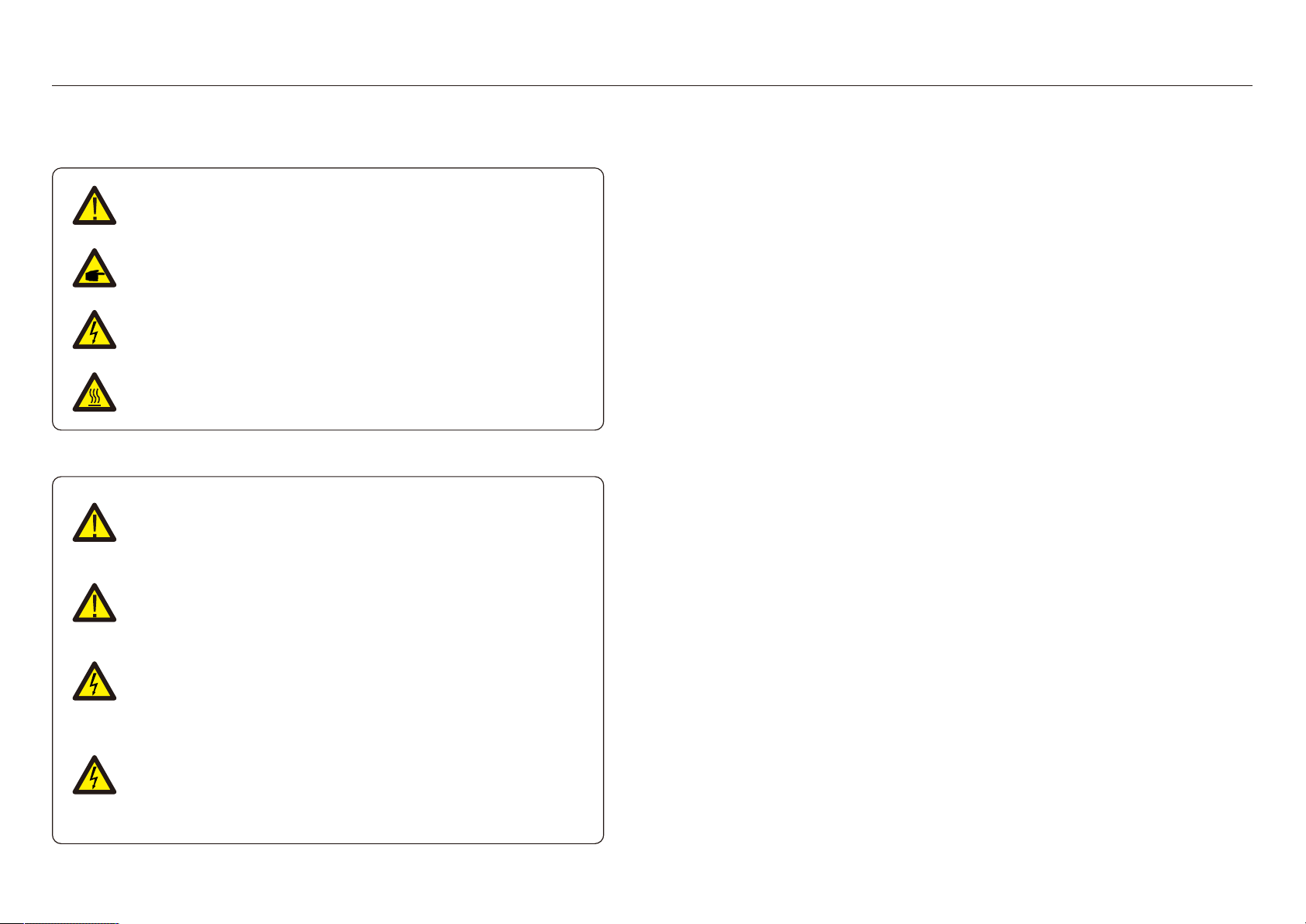
2 .1 Saf ety Sym bols
Saf ety sym bols u sed i n th i s m anu al, w h i ch h i g h li g h t potenti al saf ety ri sk s and i m portant
saf ety i nf orm ati on, are li sted as f ollow s:
2 .2 G en eral Saf et y Inst ru ct i on s
C A U T IO N :
R i sk of elect ri c sh ock f rom en erg y stored i n capaci tors.
D o not rem ove cover u nt i l 5 m i nu tes af t er di scon n ect i ng all sou rces of
su pply expect servi ce t ech ni ci an . W arrant y m ay be voi ded i f any
u nau th ori zed rem oval of cover.
2 .3 Not i ce F or Use
C A U T IO N :
C A UTIO N, R ISK O F E LE C TR IC SH O C K sym bol i n di cates i m portan t saf et y
i nst ru cti ons, w h i ch i f n ot correct ly f ollow ed, cou ld resu lt i n elect ri c sh ock .
C A U T IO N :
C A UTIO N, HO T SUR F A C E sym bol i ndi cates saf et y i nst ru ct i on s, w h i ch i f not
correctly f ollow ed, cou ld resu lt i n bu rn s.
N O T E :
NO TE sym bol i n di cates i m portan t saf et y i n st ru ct i on s, w h i ch i f n ot correct ly
f ollow ed, cou ld re su lt i n som e dam ag e or t h e destru ct i on of th e i n vert er.
W A R N IN G :
W A R NING sym bol i n di cates i m portant saf ety i n stru ct i on s, w h i ch i f not
correct ly f ollow ed, cou ld resu lt i n seri ou s i nju ry or death .
W A R N IN G :
E lect ri cal i nst allat i ons m u st be don e i n accordance w i th th e local and nati on al
elect ri cal saf ety standards.
C A U T IO N :
R i sk of elect ri c sh ock . D o not rem ove cover. Th ere i s n o u ser servi ceable
part s i nsi de. R ef er servi ci ng to q u ali f i ed and accredi t ed servi ce t ech n i ci ans.
Th e E xport P ow er M anag er h as been con stru cted accordi n g t o th e appli cable saf ety
and tech n i cal g u i deli n es.
Use t h e E xport D evi ce i n i nst allati on s t h at m eet th e f ollow i ng speci f i cati on O NLY:
1 . P erm anent i n st allati on i s req u i red
2 . Th e elect ri cal i nst allati on m u st all t h e appli cable reg u lati ons and standards.
3 . Th e E xport P ow er M anag er m u st be i nst alled accordi n g to t h e i n stru ct i on s st ated i n
t h i s m anu al.
4 . Th e E xport P ow er M anag er m u st be i nst alled accordi ng to correct tech n i cal
speci f i cati on .
5. To i nst all t h e E xport D evi ce you sh ou ld not i ce t h e ph ase of sam pli ng volt ag e and th e
di rect i on of sam pli ng cu rren t , th en you can con nect sam pli n g w i res and C T
( cu rren t transf orm er) .
W A R N IN G :
It i s f orbi dden to i n sert or u nplu g th e C T cable w i t h pow er on .
If acci dent ally di sconn ect ed t h e C T cable, please t u rn of f t h e m ai n A C
sw i tch an d w ai t f or 5 m i ns bef ore reconn ect t h e cable.

. 6 .
Li g h t
1
2
3
P O W E R
O P E R A TIO N
A LA R M
3 . O vervi ew
3 .1 F ron t P anel D i splay
3 .2 LE D St at u s Indi cat or Li g h ts
Statu s
O N
O F F
O N
O F F
O F F
O N
D escri pt i on
F i g u re 3 .1 F ron t P anel D i splay
Table 3 .1 St atu s In di cator Li g h t s
3 .3 Keypad
3 .4 LC D
Th ere are f ou r k eys i n t h e f ron t panel of t h e Inverter( f rom lef t to ri g h t ) :
E SC , UP, D O W N and E NTE R k eys. Th e k eypad i s u se d f or:
Scrolli ng t h rou g h t h e di s played opt i on s ( th e UP and D O W N k eys) ;
A ccess t o m odi f y t h e adju st able sett i ng s ( t h e E SC and E NTE R k eys) .
Th e t w o-li n e Li q u i d C ryst al D i splay ( LC D ) i s located on t h e f ront pan el of t h e E P M ,
w h i ch sh ow s t h e f ollow i ng i n f orm ati on :
.7.
E xport D evi ce pow er on
E xport D evi ce pow er of f
C om m u ni cat i on w i t h i n vert er
No com m u ni cat i on w i t h i nverter
A larm
No alarm
E xport P ow er M anag er operati on st atu s and dat a;
Servi ce m essag es f or operat or;
4 .1 Select a Locat i on f or t h e E P M
4 . Inst allati on
To select a locati on f or t h e E P M, th e f ollow i ng cri teri a sh ou ld be consi dered:
Th e t em peratu re of th e E P M cou ld u p t o 75℃.
Th e E P M i s desi g ned to w ork i n extrem e t em peratu re rang e i s f rom -2 5℃ t o 60℃.
Th e E P M sh ou ld be k ept m i ni m u m 3 00m m clearan ce f rom t h e ot h er devi ce.
Th e E P M cannot be placed i n di rect su nli g h t .
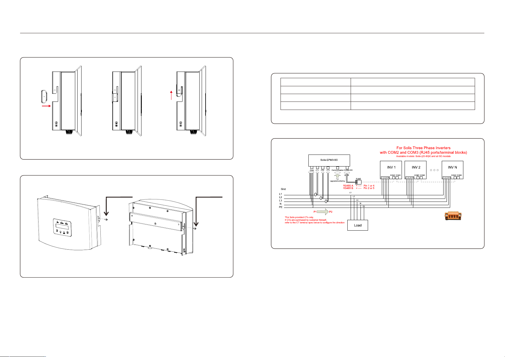
4 .2 M ou nti n g th e E P M
P lease att ach m ou nt i ng plate on to w all h ori zon tally w h ere to i n st all t h e produ ct .
Th en m ark A , B an d C to f i x m ou n t i ng plate.( see F i g u re 4 .1 )
B
A
D ri ll t h ree φ 8 h oles an d i nsert expandable sh ell i nt o t h e h oles w h i ch m ak e t h e brack et
ali g n m en t . A f t er t h at f i x t h e brack et on t h e w all.( s ee F i g u re 4 .2 )
F i g u re 4 .1 B rack et
E xpansi on screw s
B rack et
F i g u re 4 .2 F i x t h e brack et on t h e w all
C
.9.
. 8 .
4 . Inst allati on4 . Inst allat i on
Hang th e E P M i n t h e brack et by th e st eps below .( see F i g u re 4 .3 )
F i g u re 4 .3 H an g th e E P M i n th e brack et
F i x th e tw o screw at t h e si de of brack et.( see F i g u re 4 .4 )
F i g u re 4 .4 F i x t h e t w o scre w
4 .3 E lect ri cal C on necti on s
Th e E xport P ow er M anag er i s desi g n ed f or elect ri cal conn ect i on w i t h ou t rem ovi ng th e
cover.
Th e m eani n g of th e sym bols located at bot tom of t h e E P M i s li sted i n Table 4 .1 .
F i g u re 4 .5 Th ree ph ase syst em w i th Soli s-E P M 3 -5G
Syst em connect i on di ag ram i s as f ollow s:
M 4 lock i n g screw
G ri d
C T1 , C T2 , C T3
C om m _INV
A C volt ag e sam pli n g t erm i nal
A C cu rren t sam pli ng term i nals( C T)
C onn ect to soli s i n verters
Table 4 .1 Th e m eani ng of t h e sym bols located at bot t om of t h e E P M
C om m u n i cati on Mon i tori ng devi ce or Upg rade St i ck
1 2 3 4
Use t h e o ran g e conn ecto r i n s i de t h e i n verter.
P i n 1 & 2 are R s4 85 A & B IN
P i n 3 & 4 are R s4 85 A & B O UT
M 4 lock i n g scre w

.1 1 .
. 1 0 .
4 . Inst allati on4 . Installati on
F i g u re 4 .6 Th ree ph ase syst em w i th Soli s-E P M3 -5G
d. St ri p th e en d of cable t o 3 m m .
F i g u re 4 .1 1 St ri p th e cable( Th ree)
x
x= 3 m m
N
U
V
W
P E
C ross-sect i on
1 .5m m ²
F i g u re 4 .7 Si ng le ph ase system w i th Soli s-E P M 1 -5G
1 M ak e th e G ri d i nput cable
a. M easu re t h e di stance f rom E P M t o pow er di stri bu t i on box. A nd f i nd proper cable f or
g ri d i n pu t. 3 core cable f or Soli s E P M1 5G and 5 core cable f or Soli s E P M 3 5G .
b. F or si ng le ph ase i n verter i nst allat i on con n ect L, N, P E to pi n L, N, ( see f i g u re 4 .8) .
c. F or t h ree ph ase i nvert er i nst allati on connect U, V, W t o pi n1 , 2 , 3 and connect N t o
pi n4 , con n ect P E to ( see f i g u re 4 .9) .
F i g u re 4 .9 Th ree ph ase con n ect i on
3 conn ect
to W
con n ect t o N
con n ect t o
2 conn ect
t o V
1 conn ect
to U
con n ect t o
con n ect
to N
con n ect
to L
F i g u re 4 .8 Si ng le ph ase connect i on
F i g u re 4 .1 0 St ri p th e cable( Si n g le)
x
x= 3 m m
P E
L
N
C ross-sect i on
1 .5m m ² ~ 2 .5m m ²

. 1 2 . .1 3 .
4 . In stallati on4 . Installati on
3 . C onnect and fi x th e C T
To det ect th e back f low pow er, th e C Ts n eed to be i nst alled at t h e P C C
( P oi nt of C om m on C ou pli ng ) , i n st ead of t h e load branch ci rcu i t .
N ote:
F or t h ree ph ase syst em , C T1 , C T2 and C T3 m u st be i n stalled on U, V and W
w i th correct seq u ence, ot h erw i se E P M can not det ect th e correct data.
“Th e C T cable ou ter di am eter i s 6.5m m -7.5m m , cross-sect i on al area 1 .5m m ²”.
f . A ssem ble t h e connect or.
F i g u re 4 .1 4 A ssem ble con nect or( Si n g le)
F i g u re 4 .1 2 W eldi ng w i re t o con nect or( Si ng le)
e. Th rou g h th e cable to th e w ash er an d u se a su i table screw dri ver t o f i x t h e w i re to th e
conn ect or.
F i g u re 4 .1 3 W eldi ng w i re t o con n ect or( Th ree)
U
V
W
N
1
2
3
N
φ 9 . 5 m m ~ φ 1 1 . 5 m m
P E
P E
L L
φ 8 . 0 m m ~ φ 9 . 5 m m
N N
F i g u re 4 .1 5 A ssem ble connect or( Th ree)
2 . M ak e R S 4 8 5 cable ( C O M M - IN V port)
a. R ef er t o f i g u re 4 .1 6, th e R S4 85 t erm i nals f or i nverter and E P M are already assem bled.
Ti ps:R S4 85 cable: pref erred 0.5m m ², m ax 1 .0m m ².
.
F i g u re 4 .1 6 R S4 85 t erm i nal
b. R ef er t o f i g u re 4 .1 6, con nect com m u ni cati on cable bet w een i n ve rter w i th E P M , and
t h en m easu re t h e di s t ance f rom E P M t o i nvert er. Use proper cable f or R S4 85
con n ect i on. ( 0.5m m ²)
c. F ollow step1 to assem ble 2 conn ect ors t o each end of cable.
≈
In vert er 1 In vert er 2 In vert er n
R s4 85 IN | O UT R s4 85 IN | O UT R s4 85 IN | O UT
R s 4 8 5 t e r m i n a l
E P M BO X
F i g u re 4 .1 7 R S4 85 cable con n ect i on
+ t o conn ect R S4 85 A
- to con n ect R S4 85 B
φ 2 5 . 5
a. Sw i t ch of f t h e m ai n s w i t ch , di scon n ect th e li n e cables.
b. In sert th e cables t h rou g h th e C T, m ak e su re t h e P 1 on C T i s t ow ards g ri d and
P 2 i s t ow ards t h e i nvert er.
c. R econ nect t h e li ne cables.
. 1 4 . .1 5.
5. C om m i ssi on an d decom m i ssi on4 . Installati on
4 . M uti i nverter connecti on
P lease f ollow t h e previ ou s s ystem di ag ram s t o con n ect m u lti ple i nverters.
E P M can cont rol m ax 1 0 i nve rt ers ( D i f f eren t m odels are allow ed) .
Th e syst em can O NLY h as one g ri d conn ect i on poi nt .
5 . M oni tori ng
Invert ers th at conn ect ed t o E P M can be m on i tored by G i nlong W i F i /G R R S sti ck or box.
W i F i /G P R S sti ck i s u sed f or si ng le i nvert er m oni tori ng .
M ulti - i nverters m ust use W i F i / G R R S box to m oni tor.
N ote:
W h en i nve rter connect ed to E P M , no oth er m oni t ori ng devi ce i s allow ed to be
connect ed t o t h e i nvert e r.
1 . C onn ect C T conn ector, g ri d i npu t t erm i nal, R S4 85 term i nal( INV) and m oni tori ng devi ce
( i f n eeded) to t h e E P M . C on n ect th e ot h er en d or R S4 85 cable t o i nvert er.
2 . C lose t h e break er of g ri d i n pu t and st art u p E P M.
3 . Th e pow er LE D ( red) li g h t , af t er t h e st art u p i n terf ace, press u p or dow n ch eck i f t h e
act i ve pow er i s posi t i ve or 0 . If th e act i ve pow er i s n eg at i ve please ch eck th e di rect i on
of C T.
4 . P lease set i nvert er n u m ber f or m u t i -i nvert ers con nect i on.
5. F ollow t h e i n st ru ct i on of i nvert er t o start u p i n vert er. If E P M com m u ni cate w i th i n verter
su ccessf u lly, th e g reen LE D w i ll li g h t.
6. Th e def au lt allow e d back f low pow er i s 0. P lease f ollow 6.5 to ch ang e th e allow ed
back f low pow er i f ne eded.
5.1 C om m i ssi oni n g
5.2 D ecom m i ssi on i ng
In order to aovi d th e back f low pow er t o g ri d, please st op t h e i n verter bef ore stop t h e E P M.
1 . Tu rn of f th e i nvert er ou t pu t A C break er.
2 . Tu rn of f i nvert er i n pu t D C break er or pu ll ou t P V cable to stop i n verter.
3 . Tu rn of f th e g ri d i n pu t break er of E P M.
4 . D i scon n ect all cable of E P M , di sassem ble E P M af ter 5m i n s.
N ote:
If t h e C T i s i n stalled i n th e w ron g di rect i on , t h e E P M can't w ork norm ally.
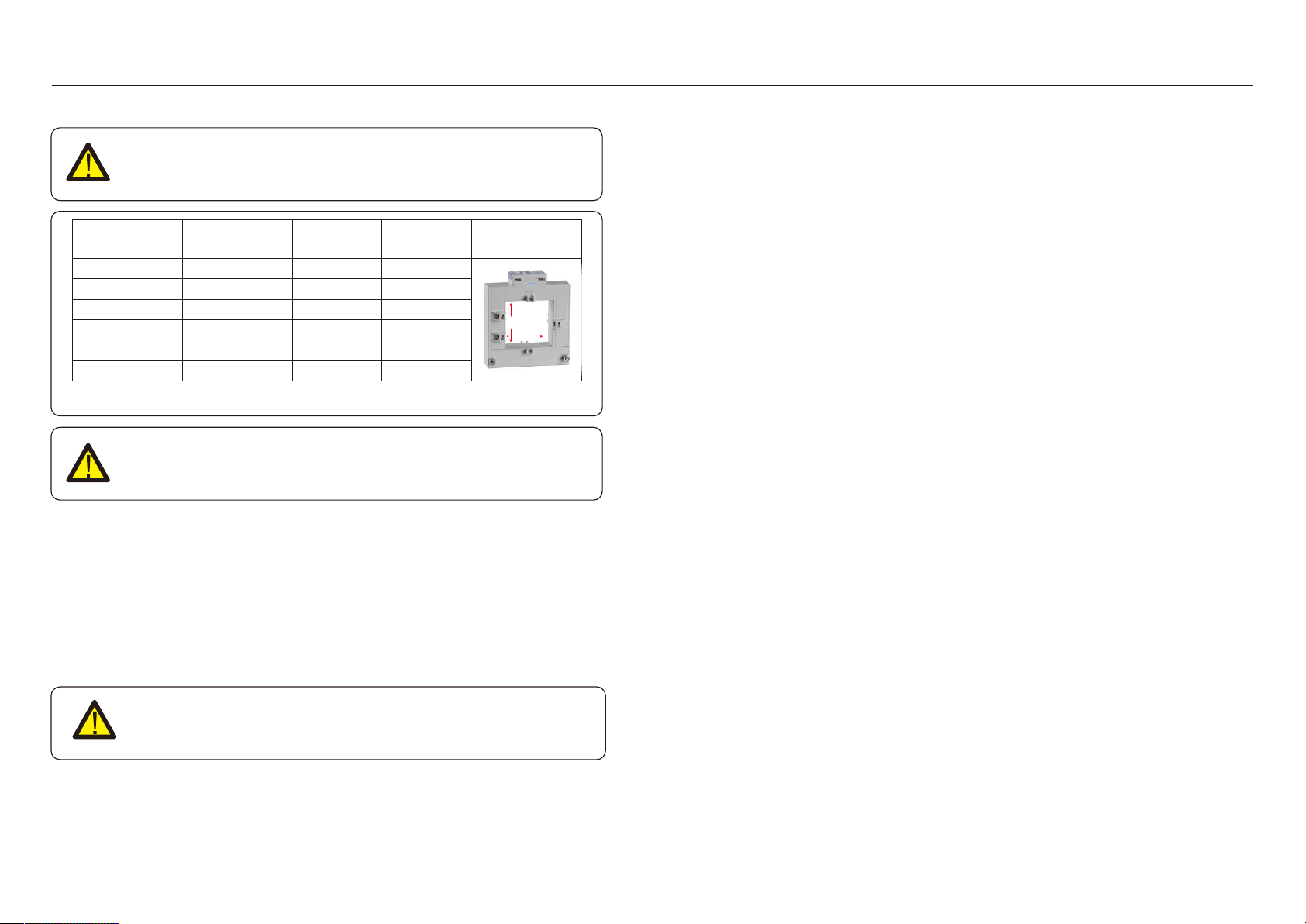
Table 4 .2 C T R ati o
N ote:
Soli s provi de t h e above opti onal C T rati o, cu stom er can select
correspondi ng C T based on th e project req u i rem ent s.
Speci f i cati on
C T-3 0×2 0-1 00A
C T-60×4 0-3 00A
C T-80×4 0-600A
C T-80×4 0-1 000A
C T- 1 60×80-2 000A
C T- 1 60×80-3 000A
A KH -0.66 K
a
e
D i m en si on s( m m )
W x H x D
90 x 1 1 4 x 4 0
1 1 4 x 1 4 0 x 3 6
1 2 2 x 1 62 x 4 0
1 2 2 x 1 62 x 4 0
1 84 x 2 54 x 52
1 84 x 2 54 x 52
Hole si ze( m m )
a x e
2 2 x 3 2
4 2 x 62
4 2 x 82
4 2 x 82
82 x 1 62
82 x 1 62
C T R at i o
1 00:5A
3 00:5A
600:5A
1 000:5A
2 000:5A
3 000:5A

5 . 2 S to p th e I n ve rte r
.1 7.
. 1 6 .
F i g u re 6.1 O perati on O vervi ew
6.1 M ai n M enu
Th ere are f ou r su bm en u s i n th e M ai n Men u ( see F i g u re 6.1 ) :
1 . Inf orm ati on
2 . Set t i ng s
3 . A dvanced In f o.
4 . A dvanced Set t i ng s
Soli s E xport P ow er M an ag er m ai n m enu provi des access to operati on al data and
i n f orm ati on. Th e i nf orm ati on i s di splayed by selecti ng " Inf orm ati on " f rom t h e m en u
and th en by scrolli n g u p or dow n .
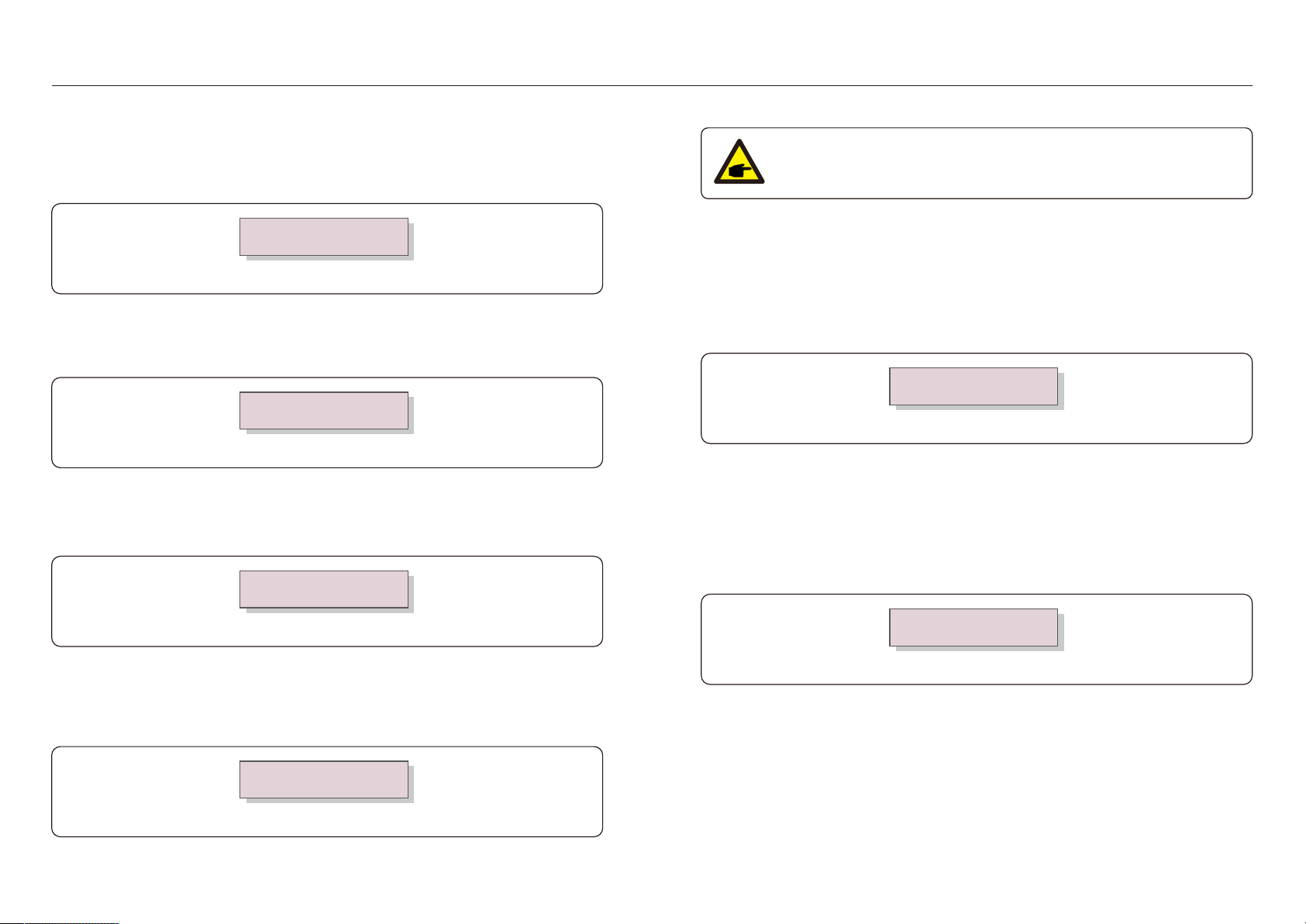
6.2 In f orm at i on
6.2 .1 Lock screen
P ressi ng t h e E SC k ey ret u rn s t o th e M ai n Men u . P ressi n g th e E NTE R k ey lock s
( F i g u re 6.2 ( a) ) or u n lock s ( F i g u re 6.2 ( b) ) t h e screen .
( b)( a)
F i g u re 6.2 Lock s and Unlock s t h e Screen of LC D
6. O perati on6. O perati on
Table 6.1 Inf orm ati on li st
D u ri n g norm al operat i on , th e di splay alt ern ately sh ow s t h e pow er of g ri d si de an d
th e operati on St atu s .Screen s can also be scrolled m anu ally by pressi ng t h e UP
and D O W N k eys. P ress th e E NTE R k ey t o access t o th e M ai n Men u .
St atu s:Norm al
01 -01 -2 003 00:02
A ct i ve_P w r:-00001 W
01 -01 -2 01 3 00:01
UP /D O W N
A ND
A UTO -SC R O LL
In f orm ati on
Set ti n g s
A dvan ced In f o
A dvan ced Sett i n g s
UP /D O W N
UP /D O W N
UP /D O W N
Th ere are 4 st at u s:
Norm al: Th e system w ork s n orm ally
R S4 85 A llF ai l: E P M h as lost com m u ni cati on w i t h A LL i n verters
C T-F ai lsaf e: C u rren t Sensor f ai led
R S4 85F ai l: E P M h as lost com m u ni cati on w i t h one or som e of th e i nvert ers
VacA _G ri d:
IacA _G ri d:
000.0V
000.0A
D i splay D escri pt i on
Vac_G ri d: G ri d volt ag e and cu rrent.
VacB _G ri d:
IacB _G ri d:
000.0V
000.0A
VacC _G ri d:
IacC _G ri d:
000.0V
000.0A
In vert er SN:
Tot al_P INV: Tot al ou t pu t pow er of i nvert ers.
E xport Li m i t ed: Invert er o u tpu t pow er percen t ag e.
F req ency: G ri d f req u ency.
A ct i ve_P w r: P ow er of t h e pow er g ri d.
A ct i ve_P w r: P ow er of t h e pow er g ri d.
A ct i ve_TP w r: :P ow er f low s t h rou g h C Ts.
Load_P w r:
Tot al_P INV:
0000.0KW
0000.0KW
E xport Li m i ted:
F req ency:
000%
00.00H z
A cti ve_A P w r:
A cti ve_B P w r:
+00000W
+00000W
A cti ve_C P w r:
A cti ve_TP w r:
+00000W
+00000W
XXXXXXXXXXXXXXX Seri es nu m ber of th e i nvert e r.
Load_P w r: Load P ow er.

.1 9.
. 1 8 .
Th e f ollow i ng su bm en u s are di splayed w h en th e Set ti n g s m en u i s select ed:
1 . Set Ti m e
2 . Set A ddress
6.3 Set ti ng s
6.3 .1 Set Ti m e
Th i s f u n ct i on allow s t i m e an d date setti n g . W h en th i s f u n ct i on i s select ed, th e LC D w i ll
di splay a scree n as sh ow n i n F i g u re 6.3 .
NE XT=<E NT> O K=<E SC >
01 -01 -2 01 6 1 6:3 7
F i g u re 6.3 Set Ti m e
P ress th e UP /D O W N k eys t o set ti m e an d data. P ress t h e E NTE R k ey t o m ove f rom on e
di g i t to th e n ext ( f rom lef t to ri g h t ) . P ress t h e E SC k ey to save t h e sett i ng s an d ret u rn to
th e previ ou s m enu .
6.3 .2 Set A ddress
Th i s f u n ct i on i s u sed to set th e address w h en m u ti i nvert ers are con n ect ed to t h ree m oni t or.
Th e address n u m ber can be assi g n ed f rom “01 ”t o “99”( see F i g u re 6.4 ) .
Th e def au lt address nu m ber i s “01 ”.
YE S=<E NT> NO =<E SC >
Set A ddress: 01
F i g u re 6.4 Set A ddress
P ress th e UP /D O W N k eys to set th e address. P ress t h e E NTE R k ey to save t h e set t i ng s.
P ress th e E SC k ey t o cancel t h e ch ang e an d retu rn t o t h e previ ou s m en u .
Select “A dvan ced Inf o.” f rom t h e M ai n Men u .
Th e screen w i ll req u i re th e passw ord as below :
YE S=<E NT> NO =<E SC >
P assw ord:0000
F i g u re 6.5 E nt er passw ord
A f t er en t er t h e correct passw ord th e M ai n Men u w i ll di splay a screen and be able t o
access t o th e f ollow i n g i nf orm ati on .
Th e screen can be s crolled m anu ally by pressi ng th e UP /D O W N k eys.
P ressi ng th e E NTE R k ey g i ves access t o a su bm enu .
P ress t h e E SC k ey t o retu rn to t h e M ai n Men u .
6.4 .1 In vert er P ow er
Th e screen sh ow s t h e i nf orm ati on of In verter P ow er f or each i n vert er w h i ch con n ect ed t o
th e E P M.
F i g u re 6.6 In verter P ow er
1 . Inverter P ow er 2 . C T C onnect S tatus 3 . V ersi on
4 . M odel Inverter 5 . C om m uni cati on D ata
6.4 A dvan ced Inf o - Tech n i ci an s O n ly
N O T E :
To access t o th i s area i s f or f u lly q u ali f i ed and accredi ted tech n i ci ans only.
E nter m enu “A dvanced In f o.” and “A dvan ced setti ng s” ( need passw ord) .
->In verter1 : 00000W
I
nverter
2 : 00000W
6. O perati on6. O perati on
.2 1 .
. 2 0 .
6.4 .2 C T C on n ect Stat u s
Th e posi ti on of t h ree-ph ase C T i nst allati on and di rect i on of cu rrent detect i on ref er t o 4 .3 ,
th en E P M detecti on w i ll di splay O K, P 1 on C T i s tow ards g ri d and P 2 i s tow ards th e i n verter,
as sh ow n i n fig u re 6.7. O t h erw i se, th e st at u s w i ll di splay " NG " w h i ch i n di cat es w ron g C T
di rect i on .
F i g u re 6.7 C T C onnect Statu s
->C TA _ connecti on:O K
C TB_ connecti on:O K
6.4 .3 Versi on
Th e screen sh ow s t h e m odel versi on and t h e sof tw are versi on of t h e In verter.
F i g u re 6.8 Versi on
Sof tw are Ver.: 1 1
6.4 .4 M odel In verter
Th e screen sh ow s t h e R ated pow er of i n vert ers th at are conn ect ed t o t h e E P M.
F i g u re 6.9 M odel Invert er
Model: 50000
6.4 .5 C om m u n i cati on D ata
Th e screen sh ow s t h e i ntern al com m u ni cati on data of t h e Invert er,
f or servi ce t ech ni ci an s on ly.
F i g u re 6 .1 0 C om m u ni cati on D at a
01 -05: 00 00 00 00 00
06-1 0: 00 00 00 00 00
6.5 A dvanced Setti n g s - Tech n i ci an s O nly
N O T E :
To access to th i s area i s f or f u lly q u ali f i ed and accredi t ed tech ni ci an s on ly.
P lease f ollow 6.4 t o ent er passw ord to access t h i s m en u .
Select A dvanced Set t i ng s f rom t h e M ai n Men u to access t h e f ollow i ng opt i on s:
1 . Inverter Q ty . S et 2 . B ack fl ow P ow er 3 . S et M eter C T 4 . Fai lS afe O N / O FF
5. B ack fl ow W ork M ode 6 . P ELD O N / O FF 7 . S y stem U pdade 8 . R eset P assw ord
9 . R estore setti ng s 1 0 . S et EP M R eg ulator
6.5.1 Inverter Q t y. Set
Th i s s u bm enu i s u sed f or setti n g i nverter n u m ber.
F i g u re 6.1 1 Invert er Q ty. Set
YES=<E NT> NO =<E SC >
Total Inverter Nu m :09
6.5.2 B ack f low P ow er
Th i s s u bm enu i s u sed f or setti n g allow ed pow er t h at i n vert er can g en erat e t o g ri d.
F i g u re 6.1 2 Set B ack f low P ow er
YE S=<E NT> NO =<E SC >
Set P ow er: +000000W
Enter th e screen ,i t sh ow s all th e nu m ber of i nverters w h i ch conected to th e E P M.
Th e nu m ber( 01 ~99) can be select by pressi ng th e UP / D O W N k eys.
P ress th e ENTE R k ey to set th e i nverter nu m ber ESC k ey to retu rn to th e previ ou s m enu .
P ress t h e UP /D O W N k eys t o set dat a.P ress th e E NTE R k ey to set back f low pow e r
Th en press UP /D O W N k eys t o ch ang e t h e n u m ber( t h e t i m es o f 1 00) .
P ress t h e E SC k ey t o save t h e set t i ng s and ret u rn t o th e previ ou s m enu .
6. O perati on6. O perati on

.2 3 .
. 2 2 .
6.5.3 Set Met er C T
Th i s f u n ct i on i s u sed to ch ang e M et er C T param et er i f cu stom er select di f f eren t Meter C T.
F i g u re 6.1 3 Set M et er C T
YE S=<E NT> NO =<E SC >
Set C T P ara:003 0:1
6.5.4 F ai lSaf e O N/O F F
Th e su bm en u i s u sed f or setti ng f ai l Saf e O N/O F F .
F ai l Saf e i ndi cates t h e com m u ni cati on s t atu s bet w een E P M and i n vert ers.
Th e def au lt setti n g i s " R u n" . D O N'T ch ang e i t w i th ou t tech ni ci an s.
F i g u re 6.1 4 F ai lSaf e O N/O F F
YE S=<E NT> NO =<E SC >
F ai lSaf e: R UN
W h en th e F ai l Saf e i s set as " R u n" . If som e of i n verters lost com m u ni cat i on w i th E P M ,
E P M ’s LC D screen w i ll di splay “ R S4 85 f ai l”; i f all i nvert ers lost com m u ni cat i on w i th E P M ,
th en th e LC D screen of E P M w i ll di splay “f ai l saf e”. A nd Th e i nvert er st ops ou t pu t pow er.
W h en th e F ai l Saf e i s set as " St op" , com m u n i cati on lost bet w een E P M and i nvert ers w i ll n ot
af f ect t h e ou tpu t of i nvert ers.
6.5.5 B ack f low W ork M ode
F i g u re 6.1 5 B ack f low W ork Mode
YE S=<E NT> NO =<E SC >
Mode:01
Th i s su bm enu i s u sed f or set back flow w ork m ode: 01 , 02 . “01 ” i s th e def au lt m ode.
Mode “01 ”, A s sh ow n i n th e fig u re 6.1 6, th e averag e li m i ti ng m ode, th e ou tpu t pow er of each
ph ase i s th e averag e of th e th ree-ph ase load pow er, and i t i s m ore th an th e ph ase of th e
low est pow er i n th ree ph ases.
In vert er
F i g u re 6.1 6
F i g u re 6.1 7
Mode “02 ”, A s sh ow n i n th e f i g u re 6.1 7 th e per ph ase li m i t i n g m ode, th e i nvert er only
g en erate t h e pow er t h at eq u als to on e of t h ree-ph ase load pow er t h at i s t h e low est
load p ow er of a cert ai n ph ase.
In vert er
P ress t h e UP /D O W N k eys t o set dat a.P ress th e E NTE R k ey t o set C T P ara.
P ress t h e E SC k ey t o sav e t h e setti ng s an d retu rn to t h e previ ou s m en u .
6. O perati on6. O perati on

.2 5.
. 2 4 .
6.5.6 P E LD O N/O F F
F i g u re 6.1 8 P E LD Sw i tch
YE S=<E NT> NO =<E SC >
Sw i tch : O F F
Th i s su bm enu i s u sed f or set P E LD on/of f . P E LD deci des E P M w ork s or n ot.
Set P E LD i s on , E P M can m on i t or and m an ag e t h e w ork i ng con di t i on of i nverters i n
real ti m e, and i t preven t s back f low g en erated. Set P E LD i s of f , w h i ch m ean s E P M
sh u tdow n s t h e f u nct i on of con t rolli ng back f low pow er.
6.5.7 Syst em Update
F i g u re 6.1 9 Syst em Update
YE S=<E NT> NO =<E SC >
Cu rrent Ver.: 1 1
Th e u pg rade of E P M’s system can reali ze by ext ernal w i re.
P lease con su lt ou r t ech n i cal en g i neer f or m ore detai ls.
6.5.8 R eset P assw ord
F i g u re 6.2 0 R eset P assw ord
YE S=<E NT> NO =<E SC >
P assw ord: 0000
F i rstly, i npu t th e ori g i n passw ord and press E nt er bu tt on;
Secon d, i n pu t th e n ew passw ord, press E n t er bu tton to save i t. UP /D O W N bu tton can be
u sed t o m ove t h e cu rsor.
Th i rd, P ress E SC bu tt on to g et t o th e previ ou s pag e.
6.5.9 R est ore Sett i ng s
F i g u re 6.2 1 R estore Setti n g s
A re you su re?
YES=<E NT> NO =<E SC >
W h en R estore Set ti n g s i s select ed, th e LC D w i ll di splay as sh ow n i n F i g u re 6.2 1 .
P ress t h e E NTE R k ey to execu te t h e set t i ng .
P ress t h e E SC k ey t o ret u rn to th e previ ou s m en u .
6.5.1 0 Set E P M R eg u lator
F i g u re 6.2 2
->Capaci ty Setti ng
Th i s i t em i s u sed to set th e su m of t h e cap aci t i es of t h e con n ected i n vert ers.
F i g u re 6.2 3
YES=<E NT> NO =<E SC >
Set C apa.: 00000000W
6. O perati on6. O perati on

8. Spe ci f i cati on s
.2 7.
. 2 6 .
7. Trou ble Sh ooti n g
Th e E P M i s desi g ned i n accordan ce w i th th e m ost i m port ant i nt ernati o n al saf ety and
E MC req u i rem ent s. B ef ore deli veri ng to th e cu stom er, th e E P M h as been su bjected t o
several tests to ensu re i ts opti m al operati on and reli abi li ty.
In case of f ai lu re, th e LC D screen w i ll di splay alarm m essag e.
Th e E P M can s h ow A larm i t self or alarm f rom i nvert er. Th ere are 3 alarm can be
sh ow ed on LC D :
1 . B ack flow
Th ere are back f low cu rrent to g ri d, cu stom er need t o stop i nvert er. and ch eck th e
con n ect i on s f or t h e R S4 85 cable bet w een E P M and i nvert er.
2 . IN V . fault
Th ere are f au lt alarm i n i n verter, n eed to ch eck i n verter statu s.
3 . Fai l safe
R S4 85 A llF ai l: E P M h as lost com m u ni cati on w i t h A LL i nvert ers
C T-F ai lsaf e: C u rrent Sen sor f ai led
R S4 85F ai l: E P M h as lost com m u ni cati on w i th on e or som e of th e i nverters
M odel
C om muni cati on
In v ert er com m u n i cati on
C om m u n i cati on i n terf ace
Maxi m u m com m u ni cati on i nvert er nu m bers
Maxi m u m com m u n i cati on di stance
Mon i t ori ng
Modbu s R S4 85
R S4 85*2
1 0
1 000m
W i f i sti ck or G P R S sti ck f or si n g le i n vert er con ect i on
W i f i box or G P R S box f or 2 ~ 1 0 i n vert ers con ecti on
S oli s-E P M 1 - 5 G
A C Input
R ated volt ag e
In pu t volt ag e rang e
In pu t volt ag e f req u en cy
In pu t cu rren t
2 3 0V,1 /N/P E
5A
1 00V~2 77V ( L t o N)
50Hz/60Hz
G eneral data
A m bi ent t em peratu re
R elat i ve H u m i di t y
In g ress prot ect i on
Self pow er con su m pt i on
D i m en si on s( W *H *D )
W ei g h t
A C connect i on
C T con ect i on
D i splay
Features
F ai lsaf e f u cti on
R em ot e u pg rated
C T speci f i cati on
C ont rol t i m e
A ccu racy
W arran t y
-2 5℃~+60℃
5% ~95%
IP 65
<5W
3 64 m m *2 76m m *1 1 4 m m
2 .1 k g
Q u i ck con n ect i on t erm i nal
P lu g term i n al
LCD,2 *2 0Z
O pt i onal( 1 f or si ng le ph ase, 3 f or Th ree ph ase)
Yes
3 %
5 years
Yes
5s

8. Speci f i cat i ons
. 2 8 .
M odel
C om m uni cati on
In vert er com m u n i cati on
C om m u n i cati on i n terf ace
Maxi m u m com m u ni cati on i nvert er n u m bers
Maxi m u m com m u n i cati on di stance
Mon i t ori ng
Modbu s R S4 85
R S4 85*2
1 0
1 000m
W i f i sti ck or G P R S st i ck f or si n g le i n vert er con ect i on
W i f i box or G P R S box f or 2 ~ 1 0 i n vert ers con ect i on
S oli s-E P M 3 - 5 G
A C Input
R at ed volt ag e
In pu t volt ag e rang e
In pu t volt ag e f req u ency
In pu t cu rren t
4 00V,3 /N/P E or 3 /P E
5A
1 00V~2 77V ( L t o N)
50Hz/60Hz
G eneral data
A m bi en t tem peratu re
R elat i ve H u m i di t y
In g ress prot ect i on
Self pow er con su m pt i on
D i m en si on s( W *H*D )
W ei g h t
A C con n ect i on
C T con ecti on
D i splay
Features
F ai lsaf e f u ct i on
R em ot e u pg rated
C T speci f i cati on
C on t rol t i m e
A ccu racy
W arran t y
-2 5℃~+60℃
5% ~95%
IP 65
<5W
3 64 m m *2 76m m *1 1 4 m m
2 .1 k g
Q u i ck con nect i on term i nal
P lu g term i n al
LCD,2 *2 0Z
O pt i on al( 1 f or si n g le ph ase, 3 f or Th ree ph ase)
Yes
3 %
5 years
Yes
5s
This manual suits for next models
2
Table of contents
Other Ningbo Ginlong Technologies Inverter manuals

Ningbo Ginlong Technologies
Ningbo Ginlong Technologies Solis 4G Operating instructions

Ningbo Ginlong Technologies
Ningbo Ginlong Technologies Solis RAI-3K-48ES-5G User manual

Ningbo Ginlong Technologies
Ningbo Ginlong Technologies Solis-2.5K-2G User manual

Ningbo Ginlong Technologies
Ningbo Ginlong Technologies Solis 4G Mini User manual

Ningbo Ginlong Technologies
Ningbo Ginlong Technologies Solis-20K User manual


