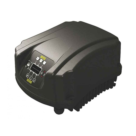
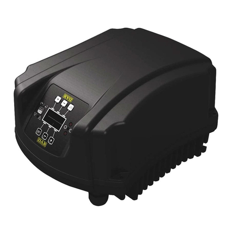
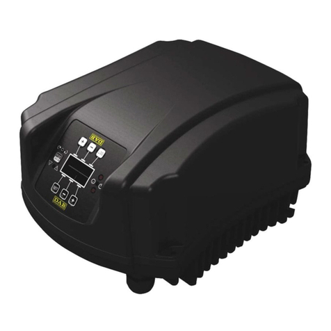
DAB MCE-22/C Operating and maintenance manual

ISTRUZIONI PER L'INSTALLAZIONE E LA MANUTENZIONE
INSTRUCTIONS POUR L'INSTALLATION ET LA MAINTENANCE
INSTRUCTIONS FOR INSTALLATION AND MAINTENANCE
INSTALLATIONS- UND WARTUNGSANLEITUNGEN
INSTRUCTIES VOOR INSTALLATIE EN ONDERHOUD
INSTRUCCIONES DE INSTALACIÓN Y MANTENIMIENTO
INSTALLATIONS- OCH UNDERHÅLLSANVISNING
РУКОВОДСТВО ПО МОНТАЖУ ИТЕХНИЧЕСКОМУ ОБСЛУЖИВАНИЮ
KURMA VE BAKIM BİLGİLERİ
ΟΔΗΓΙΕΣ ΓΙΑ ΤΗΝ ΕΓΚΑΤΑΣΤΑΣΗ ΚΑΙ ΤΗ ΣΥΝΤΗΡΗΣΗ
INSTRUCTIUNI PENTRU INSTALARE SI INTRETINERE
NAVODILA ZA VGRADNJO IN UPORABO
ИНСТРУКЦИЯ ЗА МОНТАЖ И ПОДДРЪЖКА
INSTALLÁCIÓS ÉS KARBANTARTÁSI UTASÍTÁS
MCE-22/C
MCE-15/C
MCE-11/C
V7.0

ITALIANO
pag.
01
FRANÇAIS
page
17
ENGLISH
page
33
DEUTSCH
seite
49
NEDERLANDS
pag.
65
ESPAÑOL
pág.
81
SVENSKA
sid.
97
РУССКИЙ
стр.
113
TÜRKÇE
sf.
129
ΕΛΛΗΝΙΚΑ
σελ.
145
ROMANA
pag.
161
SLOVENŠČINA
Stran
177
БЪЛГАРСКИ
Стр.
193
MAGYAR
Old.
209

ENGLISH
33
INDEX
1. KEY...............................................................................................................................................................................................33
2. GENERAL ....................................................................................................................................................................................33
2.1 Safety ..................................................................................................................................................................................34
2.2 Responsibility.....................................................................................................................................................................34
2.3 Particular warnings............................................................................................................................................................34
3. APPLICATIONS ...........................................................................................................................................................................34
4. TECHNICAL DATA ......................................................................................................................................................................34
4.1 Electromagnetic Compatibility (EMC) ..............................................................................................................................35
5. ELECTRICAL CONNECTIONS....................................................................................................................................................35
5.1 Connection to the Power Supply Line .............................................................................................................................35
5.2 Connection to the Electropump........................................................................................................................................35
5.3 Earth Connection ...............................................................................................................................................................36
5.4 Connection of the Differential Pressure Sensor .............................................................................................................36
5.5 Electrical Connections of Inputs and Outputs ................................................................................................................37
5.5.1 Digital Inputs....................................................................................................................................................................37
5.5.2 Analogue input 0-10V ......................................................................................................................................................39
5.5.3 NTC wiring diagram for measuring the fluid temperature (T and T1) ..............................................................................39
5.5.4 Outputs ............................................................................................................................................................................40
5.6 Connection for Twin Systems...........................................................................................................................................41
6. START..........................................................................................................................................................................................41
7. FUNCTIONS.................................................................................................................................................................................41
7.1 Regulating Modes ..............................................................................................................................................................41
7.1.1 Regulation with Constant Differential Pressure ...............................................................................................................42
7.1.2 Regulation with Constant Curve ......................................................................................................................................42
7.1.3 Regulation with Constant Curve with External Analogue Signal .....................................................................................42
7.1.4 Regulation with Proportional Differential Pressure ..........................................................................................................42
7.1.5 T constant function ..........................................................................................................................................................42
7.1.6 ∆T-costant function .........................................................................................................................................................43
7.2 Quick Start function...........................................................................................................................................................43
8. CONTROL PANEL.......................................................................................................................................................................43
8.1 Graphic Display..................................................................................................................................................................44
8.2 Navigation Buttons ............................................................................................................................................................44
8.3 Warning Lights ...................................................................................................................................................................44
9. MENU ...........................................................................................................................................................................................44
10. FACTORY SETTINGS..................................................................................................................................................................48
11. TYPES OF ALARM ......................................................................................................................................................................48
12. MODBUS MCE-C .........................................................................................................................................................................48
13. BACNET.......................................................................................................................................................................................48
1. KEY
The frontispiece shows the version of this document in the form Vn.x. This version indicates that the document is valid for all
software versions of the device n.y. For example: V3.0 is valid for all Sw: 3.y.
In this document the following symbols will be used to avoid situations of danger.
Situation of general danger. Failure to respect the instructions that follow may cause harm to persons and
property.
Situation of electric shock hazard. Failure to respect the instructions that follow may cause a situation of grave
risk for personal safety.
2. GENERAL
Read this documentation carefully before installation.
Installation, electrical connection and commissioning must be carried out by specialised personnel, in compliance with the general and
local safety regulations in force in the country in which the product is installed. Failure to respect these instructions not only causes
risk to personal safety and damage to the equipment, but invalidates every right to assistance under guarantee.
Ensure that the product has not suffered any damage during transport or storage. Check that the outer
casing is unbroken and in excellent conditions.
ENGLISH
34
2.1 Safety
The device contains an electronic device with inverter.
Use is allowed only if the electric system is in possession of safety precautions in accordance with the regulations in force in the
country where the product is installed (for Italy CEI 64/2). The appliance is not intended to be used by persons (including children)
with reduced physical, sensory or mental capacities, or who lack experience or knowledge, unless, through the mediation of a
person responsible for their safety, they have had the benefit of supervision or of instructions on the use of the appliance. Children
must be supervised to ensure that they do not play with the appliance.
2.2 Responsibility
The Manufacturer does not vouch for correct operation of the machine or for any damage that it may cause if it has been tampered
with, modified and/or run outside the recommended work range or in contrast with other indications given in this manual.
2.3 Particular warnings
Always switch off the mains power supply before working on the electrical or mechanical part of the system. Before
opening the equipment, wait at least 5 minutes after disconnecting it from the power supply. The capacitor of the
direct current intermediate circuit remains charged with dangerously high voltage even after the mains power has
been turned off.
Only firmly cabled mains connections are admissible. The appliance must be earthed (IEC 536 class 1,
NEC and other applicable standards).
Mains terminals and motor terminals may still have dangerous voltage when the motor is stopped.
3. APPLICATIONS
The inverter of the MCE/C series is a device conceived for the management of circulation pumps allowing integrated regulation of
the differential pressure (head); it is thus possible to adapt the performance of the circulation pump to the actual demands of the
system.
This determines considerable energy saving, a greater possibility of control of the system, and reduced noise.
The MCE-22/C inverter is designed so that it can be housed directly on the pump motor body.
4. TECHNICAL DATA
MCE-22/C
MCE-15/C
MCE-11/C
Inverter power supply
Voltage [VAC] (Tol. +10/-20%)
220-240
220-240
220-240
Phases
1
1
1
Frequency [zH]
50/60
50/60
50/60
Current [A]
22,0
18,7
12,0
Leakage current to earth [mA]
< 2
Inverter output
Voltage [VAC] (Tol. +10/-20%)
0 - V supply
0 - V supply
0 - V supply
Phases
3
3
3
Frequency [Hz]
0-200
0-200
0-200
Current [A rms]
10,5
8,0
6,5
Mechanical power P2
3 HP / 2.2 kW
2 HP / 1.5 kW
1.5 HP / 1.1 kW
Mechanical
specifications
Unit weight [kg]
(excluding packaging)
5
Maximum dimensions [mm] (WxHxD)
200x199x262
Installation
Work position
Housed on pump motor casing
IP protection rating
55
Max. ambient temperature [°C]
40
Control and
operating hydraulic
specifications
Differential pressure regulation range
1-95% pressure sensor full scale
Sensors
Type of pressure sensors
Ratiometric
Differential pressure sensor full scale
[bar]
4/10
Functions and
protections
Connectivity
Multi inverter connection
Protections
Self-protected against current overload
Temperature overload on internal electronics
Abnormal power supply voltages
Direct short-circuit between the output phases
Temperatures
Storage temperature [ºC]
-10 ÷ 40
Table 1: Technical data

ENGLISH
35
4.1 Electromagnetic Compatibility (EMC)
MCE/C inverters respect standard EN 61800-3, in the C2 category, for electromagnetic compatibility.
-Electromagnetic emissions. Residential environment (in some cases restrictive measures may be requested).
-Conducted emissions. Residential environment (in some cases restrictive measures may be requested).
5. ELECTRICAL CONNECTIONS
Always switch off the mains power supply before working on the electrical or mechanical part of the system. Before
opening the equipment, wait at least 5 minutes after disconnecting it from the power supply. The capacitor of the
direct current intermediate circuit remains charged with dangerously high voltage even after the mains power has
been turned off.
Only firmly cabled mains connections are admissible. The appliance must be earthed (IEC 536 class 1,
NEC and other applicable standards).
Ensure that the voltage and frequency on the data plate of the MCE-22/C are the same as those of the
power mains.
5.1 Connection to the Power Supply Line
The connection between the single-phase power supply line and the MCE-22/C must be made with a 3-core cable (phase + neutral +
earth). The characteristics of the power supply must satisfy the indications in Table 1.
The input terminals are the ones marked with the words LINE LN and with an arrow entering the terminals, see Figure 1.
Figure 1: Electrical connections
The minimum section of the input and output cables must be such as to guarantee correct tightening of the cable clamps, while the
maximum section accepted by the terminals is 4mm2.
The section, type and laying of the cables for supplying power to the inverter and connecting to the electropump must be chosen
according to the regulations in force. The table 2 supplies an indication on the section of the cable to be used to supply power to the
inverter. The table refers to 3-core PVC cables (phase + neutral + earth) and gives the recommended minimum section with relation
to the current and the length of the cable.
The electropump current is generally specified on the motor data plate.
The maximum supply current of the MCE-22/C may generally be estimated as double the maximum current absorbed by the pump.
Although the MCE-22/C has its own internal protections, it is still advisable to install a suitably sized thermal magnetic circuit breaker.
ATTENTION: The thermal magnetic circuit breaker and the power cables of the MCE-22/C and of the pump must be of a size suited
to the system; if the indications given in the manual do not agree with the regulation in force, use the regulation as reference.
5.2 Connection to the Electropump
The connection between the MCE-22/C and the electropump is made with a 4-core cable (3 phases + earth).
At output an electropump must be connected to a three-phase power supply with the characteristics specified in Table 1.
The output terminals are the ones marked with the words PUMP UVW and with an arrow leaving the terminals, see Figure 1.
The rated voltage of the electropump must be the same as the MCE-22/C power supply voltage.
The utility connected to the MCE-22/C must not absorb a current higher than the maximum that can be supplied, indicated in Table 1.
Check the data plates and the type of connection (star or delta) of the motor used to respect the above-mentioned conditions.
Table 3 supplies an indication on the section of the cable to be used to connect to the pump. The table refers to 4-core PVC cables (3
phases + earth) and gives the recommended minimum section with relation to the current and the length of the cable.

ENGLISH
36
The incorrect connection of the earth lines to a terminal other than the earth terminal may cause
irremediable damage to the whole equipment.
The incorrect connection of the power supply line to the output terminals intended for the load may cause
irremediable damage to the whole equipment.
5.3 Earth Connection
The earth connection must be made with cable lugs tightened as shown in Figure 2.
Figure 2: Earth connection
Cable section in mm²
10 m
20 m
30 m
40 m
50 m
60 m
70 m
80 m
90 m
100 m
120 m
140 m
160 m
180 m
200 m
4 A
1,5
1,5
1,5
1,5
2,5
2,5
2,5
2,5
2,5
4
4
4
6
6
6
8 A
1,5
1,5
2,5
2,5
4
4
6
6
6
6
10
10
10
10
16
12 A
1,5
2,5
4
4
6
6
10
10
10
10
10
16
16
16
-
16 A
2,5
2,5
4
6
10
10
10
10
10
16
16
16
-
-
-
20 A
4
4
6
10
10
10
16
16
16
16
16
-
-
-
-
24 A
4
4
6
10
10
16
16
16
16
-
-
-
-
-
-
Table valid for 3-core PVC cables (phase + neutral + earth) @ 230V.
Table 2: Section of the inverter power supply cables
Cable section in mm²
10 m
20 m
30 m
40 m
50 m
60 m
70 m
80 m
90 m
100 m
120 m
140 m
160 m
180 m
200 m
4 A
1,5
1,5
1,5
1,5
2,5
2,5
2,5
2,5
4
4
4
6
6
6
10
8 A
1,5
1,5
2,5
2,5
4
4
6
6
6
10
10
10
10
16
16
12 A
1,5
2,5
4
4
6
6
10
10
10
10
16
16
16
16
16
16 A
2,5
2,5
4
6
10
10
10
10
16
16
16
16
16
16
16
20 A
2,5
4
6
10
10
10
16
16
16
16
16
16
16
16
16
24 A
4
4
6
10
10
16
16
16
16
16
16
16
16
16
16
28 A
6
6
10
10
16
16
16
16
16
16
16
16
16
16
16
32 A
6
6
10
10
16
16
16
16
16
16
16
16
16
16
16
Table valid for 4-core PVC cables (3 phases + earth) @ 230V.
Table 3: Section of the pump power supply cables
5.4 Connection of the Differential Pressure Sensor
The MCE-22/C accepts two types of differential pressure sensor: ratiometric with full scale value 4 bar or ratiometric with full scale
value 10 bar. The cable must be connected at one end to the sensor and at the other to the pressure sensor input provided on the
inverter, marked "Press 1" (see Figure 3)
The cable has two different ends with obligatory direction of connection: connector for industrial applications (DIN 43650) on the sensor
side and 4-pole connector on the MCE-22/C side.

ENGLISH
37
Figure 3: Connections
5.5 Electrical Connections of Inputs and Outputs
The MCE-22/C has 3 digital inputs, 2 NTC inputs for fluid temperature measurement T and T1 an analogue input and 2 digital outputs
so as to be able to make certain interfaces with more complex installations.
Shown in Figure 4, Figure 5 and Figure 6 for example, are some possible configurations of the inputs and outputs.
For the installer it will be sufficient to wire up the desired input and output contacts and to configure their functions as desired (see par.
5.5.1 par. 5.5.2 and par. 5.5.4)
5.5.1 Digital Inputs
The digital inputs are screen-printed at the base of the 18-pole terminal board:
-I1: Terminals 16 and 17
-I2: Terminals 15 and 16
-I3: Terminals 13 and 14
-I4: Terminals 12 and 13
The inputs may be powered with either direct or alternating current. Shown below are the electrical characteristics of the inputs (see
Table 4)
Electrical characteristics of the inputs
DC inputs [V]
AC inputs [Vrms]
Minimum switch-on voltage [V]
8
6
Maximum switch-off voltage [V]
2
1.5
Maximum admissible voltage [V]
36
36
Current absorbed at 12V [mA]
3.3
3.3
Max. accepted cable section [mm²]
2.13
N.B. The inputs can be controlled with any polarity (positive or negative with respect to their earth connection)
Table 4: Electrical characteristics of the inputs
The example proposed in Figure 4 refers to the connection with a dry contact using the internal voltage to control the inputs.
ATTENTION: The voltage supplied between terminals 11 and 18 of J5 (18-pole terminal board) is 19 Vdc and may distribute maximum
50 mA.
If you have a voltage instead of a contact, it can still be used to control the inputs: it will be sufficient not to use the terminals +V and
GND and to connect the source of voltage to the desired input, respecting the characteristics described in Table 4.
ATTENTION: The pairs of inputs I1/I2 and I3/I4 have one pole in common for each pair.

ENGLISH
38
Figure 4: Example of Connection of Digital Inputs Start/Stop and Economy
Functions associated with the digital inputs
I1
Start/Stop: If input 1 is activated from the control panel (see par. 9) it will be possible
to command the switching on and off of the pump in remote mode.
I2
Economy: If input 2 is activated from the control panel (see par. 9) it will be possible to
active the set-point reduction function in remote mode.
I3
Quick Start: If input 3 is activated from the control panel, the pump is started at
the quick start frequency Fq (see advanced menu).
I4
Not enabled
Figure 5: Example of Connection of Quick Start Digital Input
With reference to the example in Figure 4, and if the EXT and Economy functions have been activated from the control panel, the
system behaviour will be as follows:
R1
R2
System Status
Open
Open
Pump stopped
Open
Closed
Pump stopped
Closed
Open
Pump running with set-point set by the user
Closed
Closed
Pump running with reduced set-point

ENGLISH
39
5.5.2 Analogue input 0-10V
The analogue input 0-10V is screen-printed at the base of the 18-pole terminal board:
-A1V (terminal 9): Positive pole
-GND (terminal 10): Negative pole
-A2V (terminal 4): Positive pole
-GND (terminal 5): Negative pole
The function associated with the analogue input 0-10V is that of regulating the pump rotation speed in proportion to the input
voltage 0-10V itself (see par. 0 and par. 9). The input A2V is not enabled.
Figure 6: Example of Connection of Analogue Input
N.B: The 0-10V analogue input is mutually exclusive with the NTC type temperature sensor T connected to the same poles of the 18-
pole terminal block.
5.5.3 NTC wiring diagram for measuring the fluid temperature (T and T1)
For installation of the fluid temperature sensors T and T1, refer to the following wiring diagrams, see figure 7 and figure 8.
Figure 7: Connection of NTC sensor for temperature measurement T1

ENGLISH
40
Figure 8: Connection of NTC sensor for temperature measurement T
N.B. Temperature reading via sensor T is only enabled in the following control modes: T constant increasing /decreasing
and ∆T constant .
N.B. Temperature reading via sensor T1 is only enabled in the following control modes: T1 constant increasing /decreasing
and ∆T constant .
For operating modes T constant and ∆T constant see paragraphs 7.1.5 and 7.1.6
N.B: The input of temperature sensor T type NTC is mutually exclusive with the 0-10V analogue input connected to the same poles of
the 18-pole terminal block.
5.5.4 Outputs
The connections of the outputs listed below refer to the two 3-pole terminal boards J3 and J4 indicated with the screen-printing OUT1
and OUT2 below which is also indicated the type of contact for the terminal (NC = Normally Closed, C = Common, NO = Normally
Open).
Characteristics of the output contacts
Type of contact
NO, NC, COM
Max. bearable voltage [V]
250
Max. bearable current [A]
5 If resistive load
2.5 If inductive load
Max. accepted cable section [mm²]
3.80
Table 5: Characteristics of the output contacts
Functions associated with the outputs
OUT1
Presence/Absence of alarms in the system
OUT2
Pump running/Pump stopped
In the example shown in Figure 9 the light L1 is lit when there is an alarm in the system and it goes off when no kind of malfunction is
found, whereas the light L2 is lit when the pump is running and goes off when the pump is stopped.

ENGLISH
41
Figure 9: Example of Connection of Digital Outputs
5.6 Connection for Twin Systems
To make a twin system it is sufficient to connect the 2 inverters MCE-22/C using the cable supplied, fitting it onto both inverters in one
of the 2 connectors indicated by the word Link (see Figure 3).
For correct operation of the twin system, all the external connections of the input terminal board, except for input 3 which can be
managed independently, must be connected in parallel between the 2 MCE-22/C respecting the numbering of the individual terminals
(for example, terminal 17 of MCE-22/C -1 to terminal 17 of MCE-22/C -2 and so on).
If at the time of changing over between switching off one motor and switching on the other you hear a knocking
noise, proceed as follows:
1) hold down the central “menu” key for 5 seconds;
2) scroll through the parameters until you see ET;
3) increase the value of the ET parameter in the advanced menu until the noise disappears
For the possible operating modes of twin systems see par. 9.
6. START
All the starting operations must be performed with the MCE-22/C cover closed.
Start the system only when all the electrical and hydraulic connections have been completed.
Once the system has been started it is possible to modify the operating modes to adapt better to the plant requirements (see par. 9).
7. FUNCTIONS
7.1 Regulating Modes
MCE-22/C systems allow use of the following regulating modes:
−Regulation with constant differential pressure (factory setting).
−Regulation with constant curve.
−Regulation with constant curve with speed set by external analogue signal.
−Proportional differential pressure regulation depending on the flow present in the plant.
−T constant regulation
−∆T constant regulation

ENGLISH
42
7.1.1 Regulation with Constant Differential Pressure
The head remains constant, irrespective of the water request.
This mode may be set by means of the control panel on the cover of the MCE-22/C (see par. 9).
7.1.2 Regulation with Constant Curve
The rotation speed is kept at a constant number of revolutions. This rotation speed may be set
between a minimum value and the rated frequency of the circulation pump (e.g. between 15 Hz and
50 Hz).
This mode may be set by means of the control panel on the cover of the MCE-22/C (see par. 9).
7.1.3 Regulation with Constant Curve with External Analogue Signal
The rotation speed is kept at a constant number of revolutions in proportion to the voltage of the
external analogue signal (see par. 5.5.2). The rotation speed varies in linear mode between the
rated frequency of the pump when Vin = 10V and the minimum frequency when Vin = 0V.
This mode may be set by means of the control panel on the cover of the MCE-22/C (see par. 9).
7.1.4 Regulation with Proportional Differential Pressure
In this adjustment mode the differential pressure is reduced or increased as the water request
falls or rises.
This mode may be set by means of the control panel on the cover of the MCE-22/C
(see par. 9).
7.1.5 T constant function
This function causes the circulator to increase or decrease the flow rate to keep constant the temperature measured by the NTC
sensor, connected as described in paragraph 5.5.3.
Four operating modes can be set:
T Regulation:
Increasing mode Tif the desired temperature (Ts) is higher than the measured temperature (T), the circulator increases the flow
rate until Ts is reached
Decreasing mode Tif the desired temperature (Ts) is higher than the measured temperature (T), the circulator decreases the flow
rate until Ts is reached
T1 Regulation:
Increasing mode T1if the desired temperature (Ts) is higher than the measured temperature (T1), the circulator increases the flow
rate until Ts is reached
Decreasing mode T1if the desired temperature (Ts) is higher than the measured temperature (T1), the circulator decreases the
flow rate until Ts is reached
H
Q
H
Q
Max.
Min.
H
Q
Max.
Min.

ENGLISH
43
7.1.6 ∆T-costant function
This feature allows the circulator to increase or decrease the flow rate to keep the temperature difference T-T1 constant in absolute
value.
There are 2 setpoints: dTs1, dTs2 and, therefore, you can have the following 2 situations:
-dTs1 different from dTs2:
In this case there are 5 configurable operation intervals in which the dTs setpoint can vary depending on the temperature T or T1 as
shown in the following example:
1) If T1 ≤ 10°C = > dTs = |T-T1| = 10°C
In this case, when the temperature T1 is less than or equal to 10°C, the circulator operates by acting on the flow rate to keep the
absolute difference between T and T1 constant at 10°C.
This temperature range can be useful in the ramp up phase of the thermal machine where it is more important to have a rapid
achievement of environmental comfort rather than a higher DT (case of air conditioning).
2) If 10 ≤ T1 ≤ 25°C = > 10°C ≤ dTs = |T-T1| ≤ 15°C, for example if T1= 20°C = > dTs = |T-T1| = 13.33°C
when the temperature T1 is between 10°C and 25°C, the circulator works to keep the absolute difference between T and T1 constant
at a dTs proportional to the temperature recorded by T1. For example, when T1= 20°C, the circulator keeps the absolute difference
between T and T1 constant at 13.33°C.
3) If 25°C ≤ T1 ≤ 40°C = > dTs = |T-T1| = 15°C
when the temperature T1 is between 25°C and 40°C, the circulator works to keep the absolute difference between T and T1 constant
at 15°C
4) If 40°C ≤ T1 ≤ 70°C = > 10°C ≤ dTs = |T-T1| ≤ 15°C, for example if T1= 50°C = > dTs = |T-T1| = 13.75°C
when the temperature T1 is between 40°C and 70°C, the circulator works to keep the absolute difference between T and T1 constant
at a dTs inversely proportional to the temperature recorded by T1. For example, when T1= 50°C, the circulator keeps the absolute
difference between T and T1 constant at 13.75°C.
5) If T1 ≥ 70°C = > dTs = |T-T1| = 10°
Finally, when the temperature T1 is higher than 70°C, the circulator works to keep the absolute difference between T and T1 constant
at 10°C.
This temperature range can be useful in the ramp up phase of the thermal machine where it is more important to have a rapid
achievement of environmental comfort rather than a higher DT (case of heating).
N.B.: The parameters dTs1 and dTs2 and the values of the operating ranges can be set by the user.
-dTs1 = dTs2
In this case the dTs setpoint is constant when the temperature T or T1 changes, as shown in the following example:
In this case the circulator increases or decreases the flow rate to keep the absolute difference between T and T1 constant at dTs =
15°C.
N.B.: The parameter dTs can be set by the user.
7.2 Quick Start function
This function can be useful when it is necessary to guarantee an immediate flow rate, in order to avoid a possible boiler block at the
moment of ignition. As long as input I3 is enabled, the pump remains at the preset frequency Fq (see advanced menu). In twin groups,
this input can be used independently.
8. CONTROL PANEL
The functions of the MCE-22/C may be modified by means of the control panel on the cover of the MCE-22/C itself.
On the panel there are: a graphic display, 7 navigation buttons and 3 LED warning lights (see Figure 10).

ENGLISH
44
Figure 10: Control Panel
8.1 Graphic Display
Using the graphic display it will be possible to navigate in an easy and intuitive menu which will enable you to check and modify the
system operating mode, the enabling of the inputs and the working set-point. It will also be possible to view the system status and the
log of any alarms memorised by the system.
8.2 Navigation Buttons
7 buttons are provided for navigating in the menu: 3 buttons under the display, 3 above it and 1 at the side. The buttons under the
display are called active buttons, the buttons above the display are called inactive buttons, and the button at the side is called hidden
button.
Each page of the menu is made in such a way as to indicate the function associated with the 3 active buttons (the ones under the
display).
Pressing the inactive buttons (the ones above the display) produces the effect of inverting the graphics and the buttons that were
active become inactive and vice versa. This function also allows the control panel to be installed “upside down”!
8.3 Warning Lights
Yellow light: System live signal.
If lit, it means that the system is live.
Never remove the cover if the yellow light is lit.
Red light:Warning of an alarm/malfunction present in the system.
If the light is blinking it is a non-blocking alarm and the pump can still be controlled. If the light is fixed it is a blocking
alarm and the pump cannot be controlled.
Green light: Pump ON/OFF signal.
If On, the pump is running. If Off, the pump is stopped.
9. MENU
MCE/C provides 2 menus: user menu and advanced menu.
The user menu is accessible from the Home Page by briefly pressing the central button “Menu”.
The advanced menu is accessible from the Home Page by pressing the central button “Menu” for 5 seconds.
If the menu pages show a key at bottom left it means that it is not possible to change the settings. To unblock the menu go to the
Home Page and press the hidden button and the button under the key at the same time until the key disappears.
If no button is pressed for 60 minutes, the settings are automatically blocked and the display switches off. When any button
is pressed the display lights up again and the “Home Page” appears.
To navigate in the menu, press the central button.
To return to the previous page, hold down the hidden button, then press and release the central button.
To modify the settings use the left and right buttons.
To confirm the change of a setting, hold down the central button “OK” for 3 seconds. Confirmation will be indicated by the following
icon:

ENGLISH
45
Table 6 describes the parameters sensitive to the inverter and provided in the advanced menu. To exit the advanced menu, scroll
through all parameters using the central button.
Parameter
symbol
Description
Range
Measurement
unit
Serial
Unique serial number attributed for connectivity
-
-
Fn
Electric pump rated frequency Set the value stated on
the electric pump dataplate.
50 - 200
Hz
In
Electric pump rated current Set the value stated on
the electric pump dataplate.
MCE-11
MCE-15
MCE-22
A
1.0 - 6.5
1.0 - 8.0
1.0 - 10.5
Rt
Direction of rotation. Modify this parameter to invert
the direction of rotation.
0 - 1
--
Fm
Minimum rotation frequency of the electric pump.
0 –(8/10)*Fn
Hz
FM
Maximum rotation frequency of the electric pump
(8/10)*Fn - Fn
Hz
Fq
Quick start frequency
3/10*Fn-Fn
Hz
SM
Numero di giri al minuto massimo dell’elettropompa.
12*Fn - 60*Fn
r.p.m.
--
Differential pressure type of sensor
Ratiometric with fs = 4 bar
--
Ratiometric with fs = 10 bar
H0
Maximum electric pump head.
2.0 –fs pressure sensor
m
Fc
Inverter carrier frequency
5 - 20
kHz
DR
Dry running power. If you want to enable protection
against dry running, set the value of the absorbed
power at Fn (normal frequency) in dry running
conditions, increased by 20%.
--
W
ET
Time that passes between switching off one pump
and switching on the other in twin systems.
0.0 –15.0
s
B
Characteristic constant of the NTC resistance, used
for the measurement of fluid temperatures T and T1
1-10000
°K
Td
Running time of the hydraulic circuit, it acts in an
inversely proportional way on the regulating speed in
the T and DT regulations.
0-1800
s
Bs
Parameter for setting up Booster mode
0-80
%
Ad
Modbus address of the device
1-247
Br
Serial communication baud rate
1.2, 2.4, 4.8, 9.6, 19.2, 38.4
Kb/s
Pa
Type of parity control
None, Odd, Even
Sb
Number of stop bits
1-2
Rd
Minimum response time
0-3000
ms
En
Modbus enabling
Disable, Enable
Table 6: Advanced menu –Sensitive inverter parameters
Home Page
The main settings of the system are graphically summed up on the Home Page.
The icon at top left indicates the type of regulation selected.
The icon at centre top indicates the operating mode selected (auto or economy).
The icon at top right indicates the presence of a single or twin inverter . The rotation of the
icon or indicates which circulation pump is operating.
At the centre of the Home Page is a read-only parameter which can be chosen from a small set of
parameters on Page 8.0 of the menu.
From the Home Page it is possible to access the page for regulating the contrast of the display: hold
down the hidden button, then press and release the right button.
From the Home Page it is also possible to access the read-only menu of the inverter sensitive
parameters set in the factory: hold down the central button for 3 seconds.
Page 1.0
The factory settings are set from Page 1.0 by holding down the left and right buttons at the same time
for 3 seconds.
The resetting of the factory settings will be notified by the appearance of the symbol next to the
word “Default”.

ENGLISH
46
Page 2.0
The regulating mode is set from Page 2.0. It is possible to choose from 9 different modes:
1. = Regulation with constant differential pressure
2. = Regulation with constant curve with speed set from the display.
3. = Regulation with constant curve with speed set by remote signal 0-10V.
4. = Proportional differential pressure regulation.
5. =T constant regulation increasing mode
6. = T constant regulation decreasing mode
7. = T1 constant regulation increasing mode
8. = T1 constant regulation decreasing mode
9. = ∆T constant regulation
Page 2.0 displays the three icons which represent:
central icon = setting currently selected
right icon = next setting
left icon = previous setting
Page 3.0
The regulating set-point is set from Page 3.0.
Depending on the type of regulation chosen on the previous page, the set-point to be set will be a head
(Hs), a frequency (Fs), a temperature (Ts) or a difference in temperature (dTs).
Page 5.0
Page 5.0 is displayed in all pressure regulating modes and allows the setting of “auto” or “economy”
operating mode.
“Auto” mode disables the reading of the status of digital input I2 and in fact the system always activates
the set-point set by the user.
“Economy” mode enables the reading of the status of digital input I2. When input I2 is energised the
system activates a percentage reduction of the set-point set by the user (Page 6.0).
For the connection of the inputs see par. 5.5.1
Page 6.0
Page 6.0 is displayed if “economy” mode has been chosen on page 5.0 and allows setting of the
percentage reduction value of the set-point.
This reduction will be carried out if digital input I2 is energised.

ENGLISH
47
Page 7.0
If a twin system is used (see Par. 0), on page 7.0 you can set one of the 4 possible twin operating
modes:
Alternate every 24h: The 2 inverters alternate in regulation every 24 operating hours.
If one of the 2 malfunctions, the other takes over regulation.
Simultaneous: The 2 inverters work at the same time and at the same speed. This
mode is useful when a flow rate is required that cannot be provided by a single pump.
Main/Reserve: Regulation is always performed by the same inverter (Main), the other
(Reserve) takes over only if there is a malfunction of the Main one.
Booster: The 2 inverters work simultaneously or alternately every 24 hours:
-In the case of flow rates that can be delivered by a single pump, it works in
alternating mode every 24 hours.
-In the case of flow rates that cannot be delivered by a single pump, it
works in simultaneous mode
N.B: the Booster mode can be activated only in case of constant differential pressure regulation and
proportional differential pressure regulation.
If the twin communication cable is disconnected the systems automatically configure as Single, working
completely independent of each other.
Page 8.0
On page 8.0 it is possible to choose the parameter to be displayed on the Home Page:
Measured head expressed in metres
Estimated flow rate express in m3/h
Rotation speed expressed in revs per minute (rpm)
Voltage measured on the analogue input 0-10V
Power distributed expressed in kW
Operating hours
Liquid temperature measured on the input “A1V” (18-pole terminal block)
Liquid temperature measured on the input “A2V” (18-pole terminal block)
∆T
Temperature difference of the liquid T-T1 in absolute value
Page 9.0
On page 9.0 you can choose the language in which to display the messages.
Page 10.0
On page 10.0 you can display the alarms log by pressing the right button.
Alarms Log
If the system finds any faults it records them permanently in the alarms log (up to a maximum of 15
alarms). For each recorded alarm a page composed of 3 parts is displayed: an alphanumeric code that
identifies the type of fault, a symbol that illustrates the fault in graphic mode, and a message in the
language selected on Page 9.0, giving a brief description of the fault.
By pressing the right button you can scroll through all the pages of the log.
2 questions appear at the end of the log:
1. “Reset Alarms?”
Pressing OK (left button) resets any alarms still present in the system.
2. “Delete Alarms Log?”
Pressing OK (left button) deletes the alarms memorised in the log.
Page 11.0
On page 11.0 you can set the system status in ON, OFF or controlled by a remote signal EXT (digital
input I1).
If ON is selected the pump is always on.
If OFF is selected the pump is always off.
If EXT is selected, reading of the status of digital input I1 is enabled. When input I1 is energised the
system goes ON and the pump is started (on the Home Page the messages “EXT” and “ON” appear
alternately at bottom right); when input I1 is not energised the system goes OFF and the pump goes off
(on the Home Page the messages “EXT” and “OFF” appear alternately at bottom right).
For the connection of the inputs see par. 5.5.1

ENGLISH
48
10. FACTORY SETTINGS
Parameter
Value
Regulating mode
= Regulation with constant differential pressure
Hs (Differential Pressure Set-point)
50% of the max. pump head (see inverter sensitive parameters
set in factory)
Fs (Frequency Set-point)
90% of the pump rated frequency
Tmax
50 ºC
Operating mode
auto
Set-point reduction percentage
50 %
Twin operating mode
= Alternate every 24h
Pump start control
EXT (from remote signal on input I1).
11. TYPES OF ALARM
Alarm Code
Alarm Symbol
Alarm Description
e0 - e16; e21
Internal Error
e17 - e19
Short Circuit
e20
Voltage Error
e22 - e30
Voltage Error
e31
Protocol Error
e32 - e35
Excess temperature
e37
Low voltage
e38
High voltage
e39 - e40
Excess current
e42
Dry operation
e43; e44; e45; e54
Pressure Sensor
e46
Pump Disconnected
Booster mode activated in an operation mode not allowed.
e55
Temperature sensor T error
e56
Temperature sensor T1 error
Table 7: List of Alarms
12. MODBUS MCE-C
The use of the Modbus protocol is allowed, through the installation of the cable kit 60193518 MCE MODBUS CABLE KIT.
For more information, see the web page https://dabpumps.com/mce-c.
13. BACNET
The use of the Bacnet protocol is allowed, through the installation of a Bacnet-Modbus gateway.
For more information and access to the list of recommended devices, see the web page https://dabpumps.com/mce-c.
Other manuals for MCE-22/C
1
This manual suits for next models
2
Table of contents
Other DAB Inverter manuals

DAB
DAB MCE-150/P User manual

DAB
DAB MCE-22/P Operating and maintenance manual

DAB
DAB PWM II 230 D 4.7 Operating and maintenance manual

DAB
DAB ACTIVE DRIVER PLUS M/T 1.0 Operating and maintenance manual

DAB
DAB MCE/C Series Operating and maintenance manual

DAB
DAB AD 2.2 AC Operating and maintenance manual

DAB
DAB E.SYBOX MINI 3 Operating and maintenance manual

DAB
DAB MCE-55/C Operating and maintenance manual

DAB
DAB MCE-22/C Operating and maintenance manual

DAB
DAB MCE-150/C Operating and maintenance manual