Ninja HPFSV2 User manual

Ninja Paintball Proudly made in the USA 815-477-0007
1
NINJA HIGH PRESSURE FILL STATION V2 OWNER’S MANUAL
JULY 2019
Part Number: HPFSV2
TECHNICAL SUPPORT VIDEOS AVAILABLE AT OUR YOUTUBE CHANNEL : NINJA PAINTBALL OFFICIAL
PROUDLY MADE IN THE USA!
Maintenance Kit Included
Patent Pending
SPECIFICATIONS
MAX INPUT PRESSURE 6000 PSI
MAX RATED OUTPUT PRESSURE 5000 PSI
RANGE OF ADJUSTMENT 0 –5000 PSI
GAS COMPATIBILITY NITROGEN or HIGH PRESSURE AIR (HPA)
CGA FITTING CGA 677 LEFT HANDED THREAD CONNECTION FOR BULK TANK
OPPOSITE END FOR FILL STATION ¼” -18 NPT
(4501-6000 PSI Nitrogen)
STANDARD GAUGES BULK TANK 0-6000 PSI 1/8-27 NPT
OUTPUT 0-6000 PSI 1/8-27 NPT
FILL ADAPTOR STAINLESS STEEL FOSTER 5000 PSI RATED “QD” TYPE
NOTE 1:
THE FILL STATION IS INTENDED FOR USE WITH NITROGEN, HPA (HIGH PRESSURE AIR), AND ANY OF
THE OTHER COMMONLY AVAILABLE INERT GASES.
UNDER NO CIRCUMSTANCES SHOULD THIS FILL STATION BE USED WITH OXYGEN!!!
THIS UNIT IS ALSO NOT CERTIFIED FOR USE WITH COMBUSTIBLE, CORROSIVE, OR TOXIC GASES.
NOTE 2:
THE FILL STATION IS DELIVERED WITH A 5000 PSI STAINLESS STEEL “QD” STYLE FILL ADAPTER TO
ALLOW THE ATTACHMENT OF THE SYSTEMS TO BE RECHARGED. THIS IS BY FAR THE MOST COMMON
ADAPTER, AND IS IN WIDESPREAD SERVICE ON MOST SYSTEMS CURRENTLY ON THE MARKET. THE
USER MUST BE AWARE THAT THIS QD IS RATED FOR A 5000 PSI WORKING PRESSURE, AND MUST
ONLY BE REPLACED WITH A 5000 PSI RATED QD! CALL 815-477-0007 FOR REPLACEMENT QDS.
WARNING:
DO NOT HOOK UP YOUR HIGH PRESSURE FILL STATION UNTIL YOU HAVE READ AND UNDERSTOOD THE SETUP
PORTION OF THIS MANUAL. ALWAYS WEAR SAFETY GOGGLES WHEN WORKING WITH HIGH PRESSURE GAS!!

Ninja Paintball Proudly made in the USA 815-477-0007
2
SETUP
1. THE FIRST STEP IS TO PROPERLY SECURE THE SUPPLY CYLINDER TO PREVENT TIPPING.
This can be accomplished by chaining the cylinder to a wall or post or by securing the tank in a
commercially available safety skid.
2. ATTACH THE FILL STATION TO THE BULK TANK YOU ARE USING FOR YOUR GAS SUPPLY.
Before attempting to do this, verify that your fill station is equipped with the correct CGA fitting for the
type of supply tank you plan on using. (If there is a question regarding the CGA type of a given cylinder,
look at the valve on the bulk tank. The CGA number should be stamped into one of the wrenching flats
on the valve. EXAMPLE 677)
Once you have confirmed that you have the correct fitting, you can now attach your fill station to the supply cylinder. (It
should be noted that some of the CGA thread standards use left handed threads. THE CGA 677 SUPPLIED WITH YOUR
FILL STATION IS LEFT HANDED THREAD TURN COUNTER CLOCKWISE (LEFT) TO INSTALL TO BULK TANK VALVE)
Do not use excessive torque when tightening the CGA fitting. Tighten the fitting COUNTER CLOCKWISE only enough to
eliminate any leaks. Remember; most of the cylinder valves are brass, and can be damaged by excessive torque.
3. ONCE YOU HAVE YOUR FILL STATION CONNECTED:
Make sure the control knob is turned all the way up or counter clockwise and then test the connection
by SLOWLY turning on the valve on the supply cylinder.
You should hear no leaks or flow after the initial hiss.
If gas starts to flow out of the fill connection, turn the control knob on the Fill Station counter-clockwise
until the flow stops.
This can occur if someone has turned the control knob too far clockwise prior to you connecting the Fill
Station to a gas source.
KNOW THE BOTTLE YOU’RE FILLING!
In order to properly fill a high pressure bottle, you need some basic information, all of this information comes
right off the label and the stamped markings on the bottle. Because there are Federal Standards involved, this
information is found in the form of a standard data line. An example taken from an aluminum bottle is shown below.

Ninja Paintball Proudly made in the USA 815-477-0007
3
The first information you need is the production date on the bottle.
In the United States, it is Federal Law that any gas storage vessel over two inches in diameter must be
periodically re-tested. Depending on the type of bottle, and the manufacturer, the re-test period may
be either three or five years. As a fill operator, the very first thing you should check is the date on the
bottle. As you can see in our example, our aluminum bottle was born in October of 2017. This
particular bottle has a five year re-test interval, so it would be illegal to refill this bottle after October of
2022. (At least until it had been re-tested and re-marked.) NOTE: SOME OF THE FIBERGLASS AND
CARBON FIBER BOTTLES REFERENCE THE DATE WHEN THE BOTTLE IS TO BE RETESTED.

Ninja Paintball Proudly made in the USA 815-477-0007
4
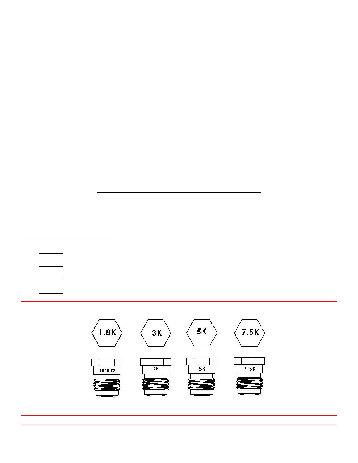
The next piece of information you want is the Working Pressure Rating.
As you can see, this information is also present in the data line on the bottle.
oREFER TO THE LABEL ON THE BOTTLE FOR PRESSURE RATING AND TEST DATES.
oUNDER NO CIRCUMSTANCES SHOULD YOU FILL AN OUT-OF-DATE BOTTLE!
oNEVER EXCEED THE PRESSURE RATING OF THE BOTTLE!!!
oEXAMINE THE BOTTLE FOR DENTS, GOUGES OR OTHER SIGNIFICANT DAMAGE. DO NOT FILL A BOTTLE
THAT HAS BEEN ABUSED OR DAMAGED.
For more information, consult the Compressed Gas Association pamphlets C-6, C-6.1, & C-6.2.
These are available online at WWW.CGANET.COM.
WARNING
IF YOU FIND THAT THERE IS NO MARKING ON THE BOTTLE OR THE LABEL HAS BEEN OBSCURED, DO NOT FILL
THE BOTTLE!
THE OPERATING CONTROLS
A DESCRIPTION OF THE OPERATING CONTROLS FOLLOWS. DO NOT HOOK UP YOUR HIGH PRESSURE FILL
STATION UNTIL YOU HAVE READ AND UNDERSTOOD THE SETUP PORTION OF THIS MANUAL.
THERE ARE TWO USER CONTROLS ON THE FILL STATION.
Output Pressure Adjustment
Control Knob.
YOUR FILL STATION IS EQUIPPED WITH TWO GAUGES
DELIVERY PRESSURE (Labeled “OUTPUT ” on the Fill Station body)
How Much Gas Is Left In Your Supply Cylinder (Labeled “BULK ” on the Fill Station body.)
OUTPUT PRESSURE ADJUSTMENT:
The Output Pressure Adjustment allows the operator to set the pressure that will be dispensed.
It is located on the top of the Fill Station, next to the control knob, and is set with a 1/8 inch Allen key.
THE CONTROL KNOB:
The Control Knob is a single control that manages both the gas delivery to the system to be filled, and the
purging of the fill line to allow disconnection.
NOTE: DO NOT OVER-RANGE THE CONTROL KNOB! DAMAGE TO THE CONTROL VALVE CAN RESULT!
THE MAXIMUM PRESSURE DELIVERED BY THE FILL STATION IS ALWAYS DETERMINED BY THE PRESSURE IN THE
BULK TANK. THE BULK TANK PRESSURE MUST BE GREATER THAN THE OUTPUT SETTING ON THE FILL STATION.
ONCE YOUR FILL STATION HAS BEEN CONNECTED TO THE BULK TANK AND PRESSURIZED, YOU CAN NOW SET THE
DELIVERY PRESSURE.
Using a 1/8 Allen key, slowly turn the Delivery Pressure Adjustment clockwise until the output gauge shows the
desired fill pressure. DO NOT EXCEED THE PRESSURE RATING ON THE BOTTLE YOU ARE FILLING

Ninja Paintball Proudly made in the USA 815-477-0007
5
Do not over-adjust, as this will cause damage to internal regulator system resulting in leaks.
Remember: You cannot dispense more pressure than the “Bulk Tank” gauge indicates!
Once the pressure is set to the output pressure you desire TURN THE CONTROL KNOB CLOCKWISE to release a
small amount of air. This will cause the output pressure gauge to move.
Reset the output pressure and repeat the release of air until the output pressure gauge adjusts to the pressure
set after the air is released.
If the unit is to be used for long term regulation check the unit regularly as the pressure can creep up or change
due to wear and contamination.
IF YOU NEED TO REDUCE THE OUTPUT PRESSURE,
Turn the Delivery Pressure Adjustment counter-clockwise.
WHEN REDUCING PRESSURE, THE OUTPUT GAUGE WILL NOT SHOW THE TRUE LOWER PRESSURE READING
UNTIL YOU HAVE ALLOWED THE GAS FROM THE PREVIOUS SETTING TO VENT BY USING THE CONTROL KNOB!
PRIOR TO HOOKING UP A SYSTEM TO BE RECHARGED, IT IS GOOD POLICY TO VERIFY THE RATING ON THE BURST DISK,
AND TO CONFIRM THAT THE VENT HOLES LOCATED ON THE SIDE OF THE BURST DISC IS UNOBSTRUCTED.
BURST DISK REPLACEMENT
ASTM compliant Unified Burst Disks are used on paintball / PCP regulators and CO2 valves for both the D.O.T.
(Department Of Transportation) required bottle protection and downstream over-pressure protection.
THE 3000 PSI (3k) BURST DISC IS FOR CO2 BOTTLES ONLY!!!
Four (4) most common bust disc.
1) 1800 PSI. used for downstream over-pressure safeties on regulators.
2) 3000 PSI. used for the D.O.T. required safety on CO2 storage bottles.
3) 5000 PSI. used for the D.O.T. required safety on 3000 PSI N2/HPA storage bottles.
4)
5) 7500 PSI. These are used for the D.O.T. required safety on 4500 PSI rated N2/HPA storage bottles.
▲WARNING SERIOUS PERSONAL INJURY OR DEATH FROM IMPROPER DISC
REPLACEMENT IT IS ABSOLUTELY ESSENTIAL THAT YOU ONLY REPLACE FAILED UNITS
WITH EXACT REPLACEMENTS!!! ASTM UNIFIED BURST DISC HAVE THE PRESSURE

Ninja Paintball Proudly made in the USA 815-477-0007
6
IDENTIFICATION STAMPED ON THE HEAD OF THE DISC. SOME DISC MAY HAVE THE
PRESSURE IDENTIFIER ON THE SIDE OF THE DISC. SEE ILLUSTRATION above. If you are
unsure do not guess see a qualified airsmith or call 815-477-0007 for assistance.
To replace a Unified Burst Disk Assembly
Unscrew the failed unit, and discard it. BURST DISC’S ARE NOT SERVICEABLE.
Visually inspect the port for damage or debris and blow out if necessary. IF THE PORT IS DAMAGED, DO NOT
REPLACE THE DISC. CONSULT AN AIRSMITH OR CALL 815-477-0007 FOR ASSISTANCE.
Screw in the new replacement unit and torque to a minimum 55 inch-pounds and maximum 95 inch-pounds.
UNIFIED BURST DISC MUST BE ASSEMBLED WITH AN INCH POUND TORQUE WRENCH!
If the Burst Disk Assembly does not seal at 95 inch-pounds, the valve should be inspected by an airsmith or call
815-477-0007 for assistance
CONNECT THE BOTTLE TO BE RECHARGED
Connect the bottle to the QD, and make sure that the QD has properly locked on the fill nipple.
Turn AND HOLD the Control Knob clockwise until you hear the flow of gas start.
Turn AND HOLD the Control Knob approximately ¼ turn further, and wait for the sound of the gas flow to stop.
Once you hear the flow cease, turn the Control Knob counter-clockwise until you hear the connection vent
down.
Once the venting has ceased, you will be able to disconnect the system from the fill station.
WARNING:
IF YOU ARE NOT ABLE TO EASILY UNLOCK THE QD, IT IS AN INDICATION THAT PRESSURE MAY STILL BE
PRESENT.
TURN THE CONTROL KNOB COUNTER-CLOCKWISE ALL THE WAY UP TO ALLOW COMPLETE VENTING OF THE
FILL STATION.
THE FILL STATION’S INTERNAL REGULATOR CONTROLS THE PRESSURE BEING DELIVERED TO THE SYSTEM, SO
THERE IS LESS OF A POSSIBILITY OF AN ACCIDENTAL OVERFILLS.
EVEN THOUGH THE CONTROL KNOB CONTROLS THE GAS FLOW DURING FILL OPERATIONS, IT IS GOOD PRACTICE
TO TURN THE CYLINDER VALVE OFF IF THE FILL STATION IS GOING TO BE LEFT UNATTENDED, OR IF YOU HAVE
FINISHED OPERATIONS FOR THE DAY.

Ninja Paintball Proudly made in the USA 815-477-0007
7
TROUBLESHOOTING
TECHNICAL SUPPORT VIDEOS AVAILABLE AT OUR YOUTUBE CHANNEL : NINJA PAINTBALL OFFICIAL
PLEASE REFER THE BILL OF MATERIALS (BOM)
Maintenance kit included
THE FILL STATION INCORPORATES (3) 1/8-27 NPT PLUG PORTS, ITEM #1 ON THE BOM. THE
(3) PORTS ARE LABELED “DO NOT REMOVE” PLEASE DO NOT REMOVE THE PLUGS
Fill Station Leaks from the FOSTER QD # 8 while filling –#34 Inlcuded in PMKIT
QD oring needs replacement the #34 010 oring is located behind the ball bearings in the female quick
disconnect.
Remove the old oring with a pick and then squeeze the new #34 oring into the grove.
Starting with one end of the oring in the groove and then using a blunt object to push the other side in will
usually get it in place.
Leaks from the FOSTER QD #8 all the time –
FILL STATION leaks whenever the air is on from the female qd the valve seat needs to be serviced and please
send it in for a rebuild.
Leaks from the Valve Actuator #23 while filling –
Fill Station leaks from the Valve Actuator #23 while filling.
Replace 004 oring #20
Unscrew the top of the –actuator plug assembly –from the body. A wrench may be needed to get the assembly
started unscrewing but take care not to damage the body or the assembly.
Unscrew the housing nut by using a 3/4” thin wall socket. Counter clockwise will remove the nut and remove
fully. No ratchet or tool is needed as the nut is only installed by hand and will turn and remove easily.
Remove the actuator shaft and return spring from the unit. Clean and inspect the shaft, replacing the shaft is
usually not needed unless the shaft is bent.
Using a 3/16” allen wrench remove the oring jam nut

Ninja Paintball Proudly made in the USA 815-477-0007
8
The # 20 004 oring is located in the pocket and a pick will remove the oring but take care not to damage or
scratch the internals during removal.
Make sure the unit is clean
Reassembly is the reverse, install the #20 004 and push the oring into place with a blunt object.
Screw the oring jam nut into place –snug and do not over tighten or torque it in.
Place the return spring in the unit and lube the bottom 1/3rd of the shaft, then insert the shaft into the unit.
Install the retaining nut into place. You may need to push down on the nut with an allen wrench through the
drive hole of the socket to get the nut to start catching the threads. Do not overtighten.
Install the top unit in place.
Fill Station does not hold output pressure and creeps up –
The PB-HP seat #6 needs to be replaced, Included in PMKIT
Fill Station does not vent when control knob is turned all the way up –
You are unable to release the female qd due to pressure left in the Fill Station
Control assembly needs to be reset and the 004 #20 replaced.
Follow the rebuild procedures to reset the control assembly and change the valve oring #20.
Fill Station is holding the air and the Fill Station has to be removed from the bulk filling tank.
Turn off the bulk tank and when the cga nut is broken loose from the bulk tank the fill station will de- gas
allowing you to remove the cylinder being filled and rebuild the unit.

Ninja Paintball Proudly made in the USA 815-477-0007
9

Ninja Paintball Proudly made in the USA 815-477-0007
10
Table of contents
Other Ninja Paintball Equipment manuals