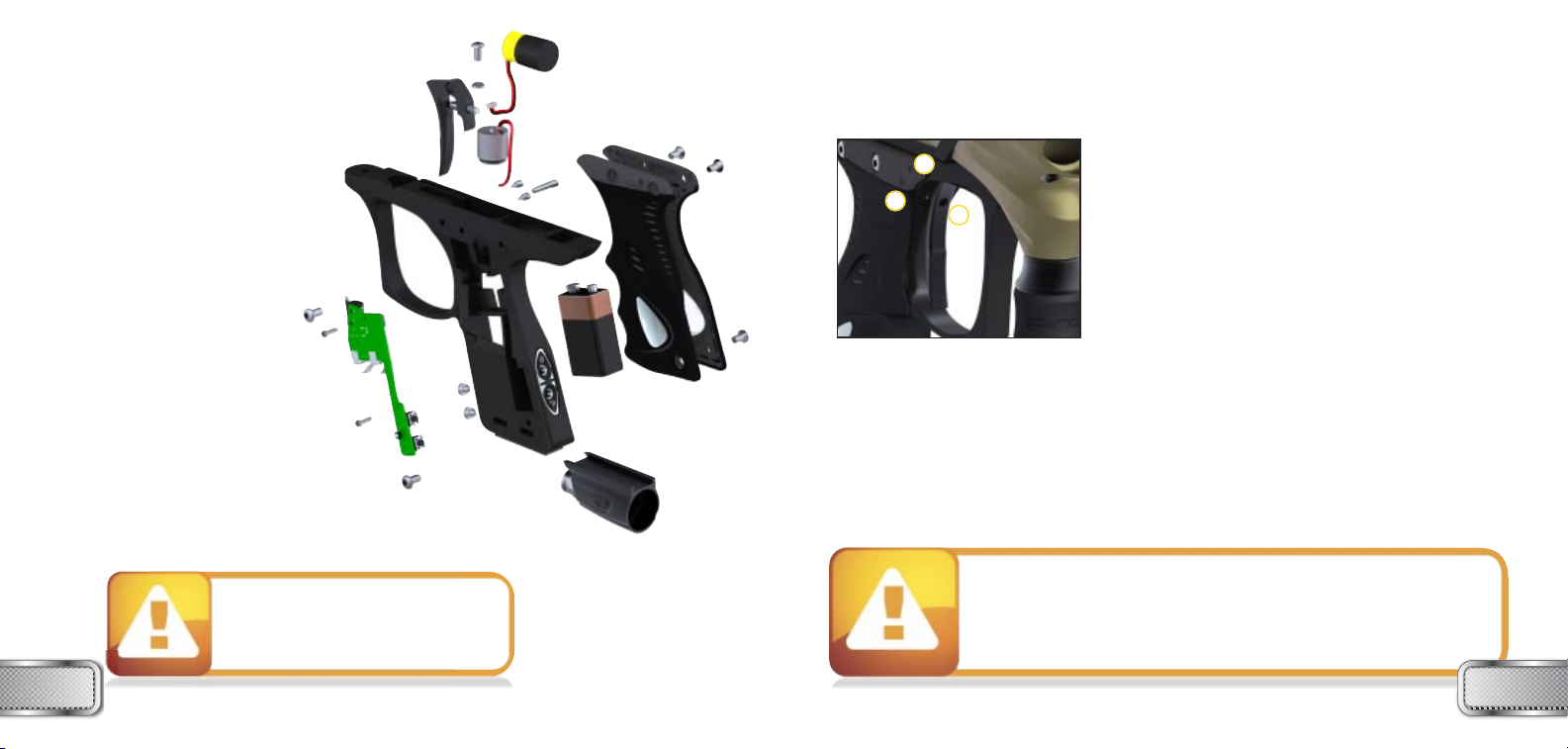
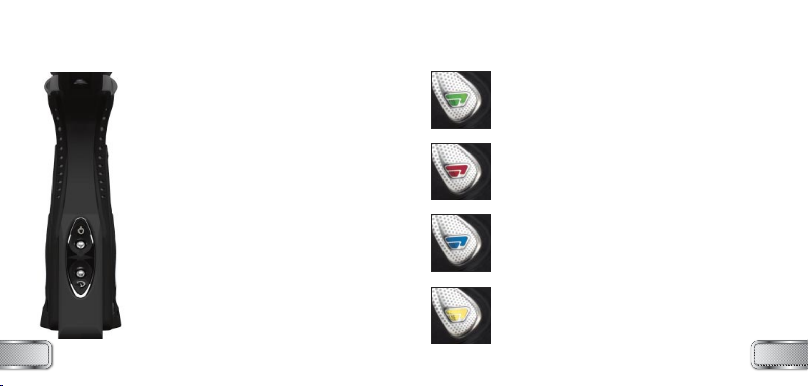
Proto SLG ULTRALITE User manual

™
Proto Paintball
USA 10637 Scripps Summit Ct. San Diego, CA 92131
P 858-536-5183 F 858-536-5191
EUROPE Unit 1, ZK Park, 23 Commerce Way
Croydon, Surrey CRO 4ZS United Kingdom
P +44 (0) 20-8649-6330 F +44 (0) 20-8649-6339
ASIA No. 253, Guojhong Rd., Dali City
Taichung County 412, Taiwan (R.O.C.)
P +886 (0) 4-2407-9135 F +886 (0) 4-2407-2090
www.protopaintball.com
www.dyematrix.com
Copyright ©2008 DYE Precision, Inc. The stylized “proto” logo and the “P” logo are
either registered trademarks, trademarks, or design trademarks of DYE Precision, Inc.
DYE Precision, Inc. U.S. Patent # 5,613,483. OTHER U.S. AND INT’L PATENTS PENDING.
Covered by one or more of the following U.S. Patents, 5,613,483; 5,881,707; 5,967,133; 6,035,843 and 6,474,326.
®
®

TABLE OF CONTENTS
- IMPORTANT SAFETY INSTRUCTIONS AND GUIDELINES . . . . . . . . . . . . . . . . . . . . . . . . PAGE 02
- QUICK START UP GUIDE . . . . . . . . . . . . . . . . . . . . . . . . . . . . . . . . . . . . . . . . . . . . . . . . . . . PAGE04
- SLG™ BOARD SETTINGS AND FUNCTIONS . . . . . . . . . . . . . . . . . . . . . . . . . . . . . . . . . . . PAGE 06
- TRIGGER ADJUSTMENTS . . . . . . . . . . . . . . . . . . . . . . . . . . . . . . . . . . . . . . . . . . . . . . . . . . PAGE 1 1
- SLG™ BOLT ASSEMBLY AND MAINTENANCE . . . . . . . . . . . . . . . . . . . . . . . . . . . . . . . . . PAGE 12
- SLG™ BOLT O-RING LIST . . . . . . . . . . . . . . . . . . . . . . . . . . . . . . . . . . . . . . . . . . . . . . . . . . . PAGE 15
- FEED NECK ADJUSTMENT . . . . . . . . . . . . . . . . . . . . . . . . . . . . . . . . . . . . . . . . . . . . . . . . . PAGE 16
- AIRPORT ADJUSTMENTS . . . . . . . . . . . . . . . . . . . . . . . . . . . . . . . . . . . . . . . . . . . . . . . . . . PAGE 18
- VELOCITY ADJUSTMENT . . . . . . . . . . . . . . . . . . . . . . . . . . . . . . . . . . . . . . . . . . . . . . . . . . PAGE 20
- HYPER3™ REGULATOR ADJUSTMENT AND MAINTENANCE . . . . . . . . . . . . . . . . . . . . . PAGE 21
- ANTI CHOP EYES AND BALL DETENTS . . . . . . . . . . . . . . . . . . . . . . . . . . . . . . . . . . . . . . PAGE 22
- TROUBLE SHOOTING . . . . . . . . . . . . . . . . . . . . . . . . . . . . . . . . . . . . . . . . . . . . . . . . . . . . . PAGE24
- EXPLODED VIEW . . . . . . . . . . . . . . . . . . . . . . . . . . . . . . . . . . . . . . . . . . . . . . . . . . . . . . . . .PAGE28
- WARRANTY AND LEGAL INFORMATION . . . . . . . . . . . . . . . . . . . . . . . . . . . . . . . . . . . . . PAGE 29
WWW.PROTOPAINTBALL.COM
SLG
™ULTRALITE OWNER’S MANUAL
INCLUDED WITH YOUR PROTO SLG™ ULTRALITE
- SLG™ Ultralite Marker
- Allen tool set including 0.05”, 1⁄16”, 5⁄64”,
3⁄32”, 1⁄8”, 5⁄32”, 3⁄16” and 1⁄4”.
-1⁄4oz. Slick Lube™
- Parts Kit
- Barrel Sock
- Owner’s Manual
- Warranty Card
- 9V Battery
The SLG™ comes with the tools required to perform general maintenance and setting up.
For a complete service, the following tools are required:
- 5/16” allen key
- #0 Phillips head screw driver
- A sharp pick to remove O-rings
WWW.PROTOPAINTBALL.COM 1

• Always chronograph the SLG™ marker before playing paintball.
• Never look into the barrel or breech area of the SLG™ when the
marker is switched on and able to fire.
• Compressed gas is dangerous, do not allow compressed gas to
come in contact with your skin or try to stop a leak by covering it
with your hand.
• Always fit a barrel blocking device to your SLG™ when not in use on
the field of play.
• The owner’s manual and any related warnings or instructions should
always accompany the product for reference or in the event of resale
and new ownership.
• Do not point the SLG™ marker at anything that you do not intend to
shoot.
• Do not shoot at people, animals, houses, cars or anything not related
to the sport of paintball.
• Do not fire the SLG™ without the bolt screwed in completely.
• If you read these instructions and do not fully understand them or are
unsure of your ability to make necessary adjustments properly,
call DYE Precision or your local pro shop for help.
• The SLG™ marker is not a toy. Misuse may cause serious injury or death.
• Please read, understand and follow the directions in the SLG™
owner’s manual.
• Eye protection that is designed specifically for paintball and meets
ASTM/CE standards must be worn by user and persons within range.
• Recommend 18 years or older to purchase. Person under 18 must
have adult supervision.
• Do not put your finger inside the breech of the SLG™. Moving bolt can
cause a serious injury.
• Always treat the SLG™ marker as if it were loaded and able to fire.
• Only use compressed air or nitrogen gas in the SLG™ marker.
DO NOT USE CO2.
• Do not exceed 850 psi input pressure.
• Only use .68 caliber paintballs that meet ASTM/CE standards.
• Ensure all air lines and fittings are tightened and secured before
gassing up the SLG™.
• Never shoot the SLG™ marker at velocities in excess of 300 feet
per second, or at velocities greater than local or national laws allow.
WWW.PROTOPAINTBALL.COMWWW.PROTOPAINTBALL.COM
2 3
WARNING
IMPORTANT SAFETY INSTRUCTIONS AND GUIDELINES
WARNING
IMPORTANT SAFETY INSTRUCTIONS AND GUIDELINES

QUICK START UP GUIDE
Before playing with your new SLG™ paintball marker there
are a few important steps to take.
STEP 1. BATTERY INSTALLATION
A. Remove three right hand side grip panel screws with a
3⁄32” allen key.
B. Open grip panel and install 9V battery into the
connector inside the frame.
C. Notice + and - markings on frame to install battery
correctly.
D. Close grip panel and tighten the three screws back into
place. When closing the panel observe that no wires get
caught between the frame and the grip panel.
STEP 2. BARREL INSTALLATION
A. Screw on the barrel to the front of the SLG™. Make sure
it threads all the way in and has a snug fit.
B. Attach the barrel sock so that it covers the tip of the
barrel and secure the strap around the back of the SLG™.
STEP 3. LOADER INSTALLATION
Tighten your loader into the adjustable feedneck using a
5/32” allen key. For best performance, use a force feeding
motorized loader.
STEP 4. ATTACHING GAS SOURCE
Be sure there are no paintballs loaded in the breech of the SLG™.
If the bolt is in the forward position, a ball can be fired when gas
enters the marker. Screw on a preset air system into the airport
located on the bottom of the grip frame. Be sure the air system is
screwed all the way into the Airport. If there is a leak while
screwing in the air system or if no gas enters the SLG™ when the
air system is screwed all the way in, consult page 19 in this manual
for pin depressor adjustment.
STEP 5. TURNING ON THE SLG™ AND CHECKING THE VELOCITY
A. Make sure you and everybody around you is wearing
ASTM/CE approved paintball masks.
B. Press and hold the top button located behind the grip
frame until the SLG™ turns on. WARNING: The SLG™ is now LIVE.
Make sure barrel sock is in place and do not point the SLG™
towards anything you don’t intend to shoot.
C. Fill up the loader with .68 caliber paintballs.
D. Shoot the SLG™ over a chronograph to check the velocity.
If adjustment is needed, adjust the velocity by turning the
Hyper3™ velocity adjustment screw with a 3⁄16” allen key.
In (clockwise) will reduce the velocity and out (counter clockwise)
will increase the velocity. After each adjustment
it takes a few shots before the change can be seen on the
chronograph. Never adjust the SLG™ to shoot faster than
300fps or what the field rules/local laws permit.
QUICK REFERENCE
USING YOUR MARKER
QUICK REFERENCE
USING YOUR MARKER
WWW.PROTOPAINTBALL.COMWWW.PROTOPAINTBALL.COM
4 5

SLG™ BOARD
SETTINGS AND FUNCTIONS
SLG™ BOARD
SETTINGS AND FUNCTIONS
NOTE: The eye is always activated when you turn the marker on.
BUTTONS AND LED LIGHT INDICATOR
There are two buttons and an LED light indicator mounted inside
the frame of the SLG™. The two buttons are accessible on the back
side of the frame. The LED is visible on the left side of the grip.
The top button is used to turn the SLG™ ON and OFF. The bottom
button is used to turn the eye feature of the SLG™ ON and OFF.
To turn the SLG™ ON press and hold the top button until the LED
light turns on. The eye feature is always on when the SLG™ is turned on.
To turn off the eye feature press and hold the bottom button until the
LED light starts blinking Red indicating the eye feature is turned off.
In normal operation mode the LED light indicator shows you the
following information:
Blue:Boot up Sequence
Red: No ball detected inside the SLG™, eye is turned on
Green: Ball detected inside the SLG™, eye is turned on
Blinking blue: A low battery, change battery as soon as possible
Blinking red: Eye is turned off
Blinking green: Eye blocked. Either the eye is dirty, the
marker is not gassed up, there is bad connection between
the board and the eyes, or the battery is low.
SETTINGS AND CONFIGURATION MODE
There are four settings that can be altered on the SLG™ circuit board.
1. Trigger sensitivity
2. Dwell
3. ROF (Rate Of Fire)
4. Fire Mode
DIP switch 1, is used for factory reset/tournament lock. When it's OFF the
gun is always set back to stock settings (semiauto, 15 bps, trigger
sensitivity 5).
To change the board settings you must turn ON the factory settings lock.
To do this, turn DIP switch number 1 ON.
Settings 1-4 are changed from a configuration mode.
To change settings 1-4 you will need to activate the configuration mode.
To activate the configuration mode, turn your marker off, open the three
left side grip panel screws with a 3⁄32” allen key and set DIP switch 2 to
the ON position. Next, turn your marker on.
The LED will cycle through all colors for one second to indicate that you
have entered the configuration mode.
To cycle through different settings, pull and release the trigger.
GREEN – TRIGGER SENSITIVITY (VALUES 1 - 20)
(factory default 5)
Trigger sensitivity is the amount of time that the trigger has to be
released before the next trigger pull is allowed. In some situations with
too low of a value, the marker may begin to shoot full-auto.
RED – DWELL (VALUES 1 - 5)
The Dwell setting is used to change the amount of
time the solenoid is activated. Shorter time will
consume less power. If the time is too short the
SLG™ will not fire.
WWW.PROTOPAINTBALL.COMWWW.PROTOPAINTBALL.COM
6 7
DWELL
RATE OF FIRE
FIRE MODE
TRIGGER SENSITIVITY
18 ms
29 ms
310 ms (default)
411 ms
512 ms

SLG™ BOARD
SETTINGS AND FUNCTIONS
SLG™ BOARD
SETTINGS AND FUNCTIONS
BLUE – RATE OF FIRE (VALUES 1-20)
The ROF setting is used to set the
maximum rate of fire of the SLG™.
The values do not correspond directly
to a certain Balls Per Second (BPS)
value. You will need to use the table
below to locate your desired
maximum ROF setting. The factory
default is 14 (13.33 BPS). This setting
is used both when the Eye function is
turned on and off.
YELLOW – FIRE MODE (VALUES 1-4)
The fire mode setting is used to select the fire mode of the SLG™. Factory default is semi
automatic mode; one trigger pull shoots out one paintball. The Millennium mode and the PSP
mode follow the rules of the paintball tournament series.
Value 1 – Semi automatic mode
Value 2 – Millennium™ Mode (2008 rules)
Value 3 – PSP™ mode
Value 4 – NXL™
TO CHANGE A VALUE OF A SETTING
1. While in the configuration mode choose the color you wish to change by pulling the trigger.
2. When the LED indicates the color you wish to change, pull and hold the trigger until the LED
starts to flash.
3. The LED will flash as many times as the previous setting was and it will then turn off. Now pull
the trigger as many times as you wish the new setting to be.
4. When done the LED will cycle through all the colors again to indicate setting was saved and
turn back to green. You can now change another setting or quit the configuration mode.
110.00 BPS
211.10 BPS
311.63 BPS
411.76 BPS
511.90 BPS
612.05 BPS
712.20 BPS
812.35 BPS
912.50 BPS
10 12.60 BPS
11 12.82 BPS
12 12.99 BPS
13 13.16 BPS
14 13.33 BPS (default)
15 13.51 BPS
16 13.70 BPS
17 13.89 BPS
18 14.08 BPS
19 14.29 BPS
20 14.49 BPS
21 14.71 BPS
22 14.93 BPS
23 15.15 BPS
24 15.38 BPS
25 15.63 BPS
26 15.87 BPS
27 16.13 BPS
28 16.39 BPS
29 16.66 BPS
30 20.00 BPS
31 22.22 BPS
32 25.00BPS
33 28.57 BPS
34 33.33 BPS
Normal Mode Configuration Mode
WWW.PROTOPAINTBALL.COMWWW.PROTOPAINTBALL.COM
8 9
Increasing ROF too high will increase probability of ball breakage.
If this occurs decrease ROF setting.

TRIGGER
ADJUSTMENT
SLG™ BOARD
SETTINGS AND FUNCTIONS
BATTERY
The 9V battery will last for about
20,000 shots. Please be aware that
there are substantial differences in
performance between different brands of
batteries. Use of high quality alkaline or
lithium ion batteries is recommended for
maximum battery life. If you plan not to
use your marker for a long period
of time (a month), it is
recommended that you remove the
battery from the marker. When the
battery voltage starts to go too low, the
marker will not fire with every trigger pull.
For tournament use, it is recommended to
change the battery for each tournament.
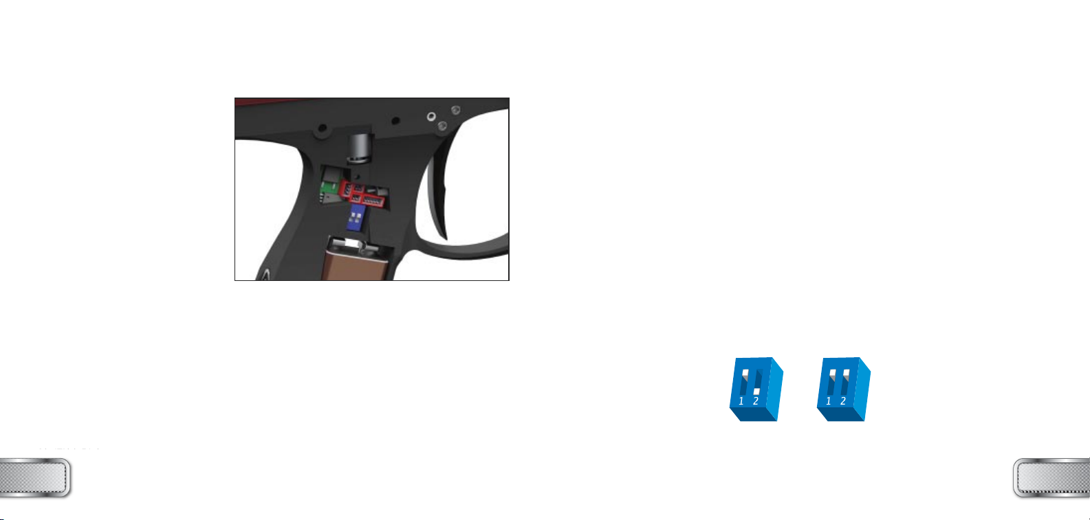
CHANGING THE BATTERY
The battery is housed on the right side of the grip
frame. To access the battery, remove the three screws holding the right side
grip panel down. Use a 3⁄32” allen key. When inserting a new battery notice the
+ and - marks on the frame. The positive lead of the 9V battery goes to the left and the negative
lead to the right.
NOTE: If the marker will not
function with the eye on,
there is a good chance the
battery needs to be
changed.
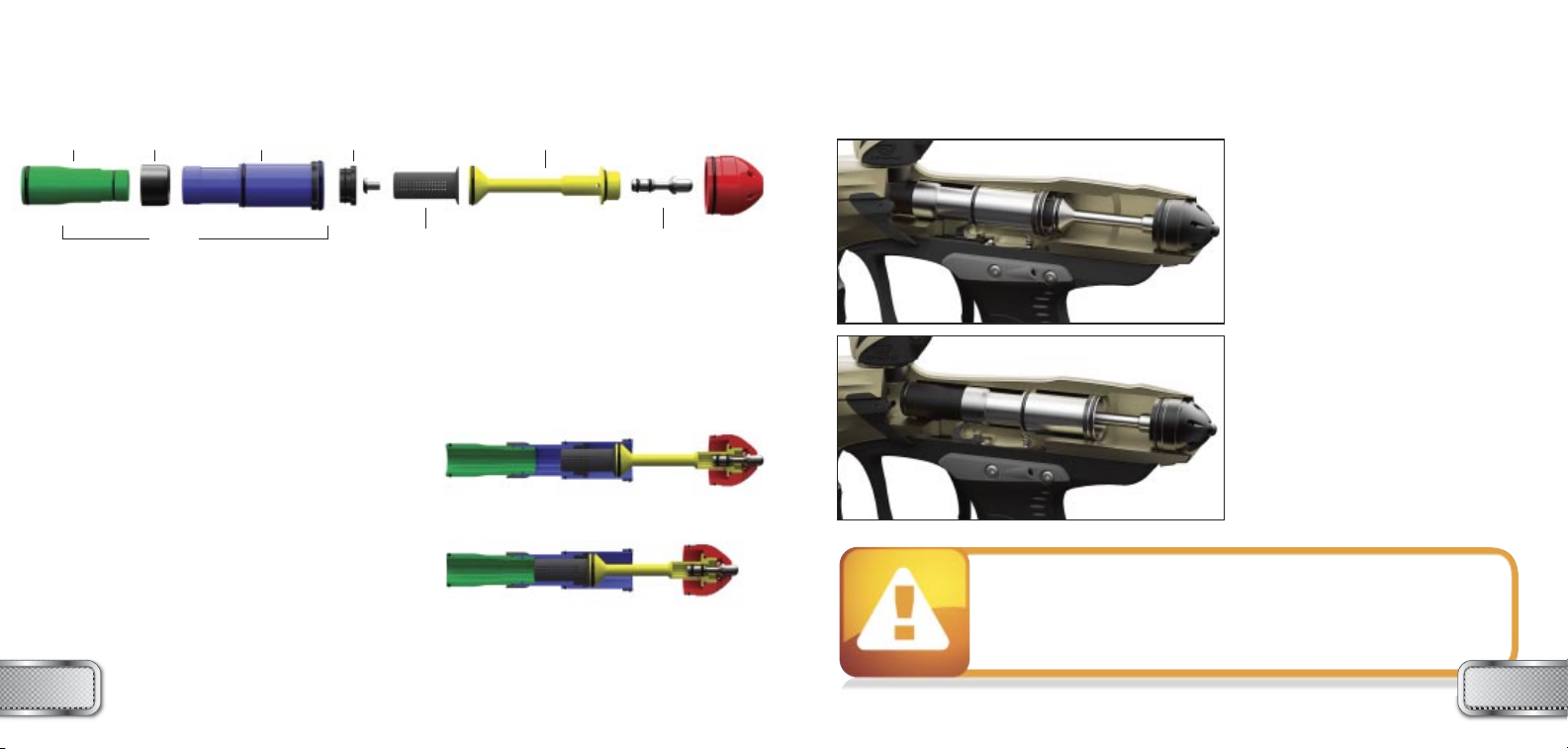
ADJUSTING YOUR TRIGGER
The trigger’s forward travel, over travel and spring tension
are fully adjustable so that the user can fine-tune the
trigger to his or her exact liking. You do not need to remove
the frame from the gun in order to adjust the trigger pull.
• There are two adjustment screws located on the right side
of the Ultralite frame and one adjustment screw behind the
trigger. The two screws on the side of the frame adjust the
travel of the trigger. The one located behind the trigger is
used to change the tension of the trigger spring.
• Use a 5⁄64” allen key to make all desired adjustments.
TO ADJUST TRIGGER TRAVEL (SEE FIGURE 1)
• The screw toward the front of the trigger (1) controls the trigger’s length of pull. NOTE: If this
screw is adjusted too far, the switch will be held down at all times and the marker will not fire.
•The screw toward the rear of the trigger (2) controls how far the trigger will travel after it
reaches the firing point. NOTE: If this screw is adjusted too far, the trigger will not be allowed to
travel far enough to depress the switch and fire the marker.
TO ADJUST SPRING TENSION (SEE FIGURE 1)
• Turn the screw located through the hole in the trigger (3) in or out to reach the desired tension.
Fig. 1
2
1
3
• Be sure the trigger is not adjusted to the point where it is too sensitive
and may cause accidental discharge of the marker.
• Removing the trigger spring will cause premature wear on the microswitch,
resulting in failure.
•Be sure you do not pinch the wires between the frame and body when
reattaching the frame to the body.
• A low battery will not be able to
power both the ACE eye and the
trigger switch, causing ACE eye failure.
• If the battery is low, the marker will
not fire with every trigger pull.
WWW.PROTOPAINTBALL.COMWWW.PROTOPAINTBALL.COM
10 11
FIGURE 1

The SLG™ BOLT is the main component of the SLG™ marker. In order to
achieve the best possible performance, it is essential that the SLG™ BOLT
is kept clean, well lubed and in good working order.
The SLG™ BOLT should be cleaned and re-lubed every 10,000 shots or
after breaking paint or playing in severe conditions.
The SLG™ bolt kit is composed of a 2 piece bolt, plunger, and back cap.
To remove the bolt kit, unscrew the back cap using a
1⁄4” allen key. Insert the allen key into the back cap,
while depressing the bleed button. If there is any air
remaining in the SLG™, it will be purged when the bleed
button is depressed. If air continues to leak from the
bleed system, your air system is still feeding air into the
SLG™.
De-activate the air system and continue with the bolt
maintenance. Once you have unscrewed the back cap
and removed it from the body, the bolt should slide out.
For regular maintenance there is no reason to
disassemble the bolt kit any further.
FORWARD POSITION
BOLT
(DO NOT DISASSEMBLE FOR
REGULAR MAINTENANCE)
SILENCER BLEED BUTTON
SLG™ BOLT
ASSEMBLY
SLG™ BOLT
OPERATION
BOLT BACK
SOFT
RUBBER
CUSHION BACK CAPBOLT TIP PLUNGER
RING HOW IT WORKS
At rest, when the bolt is in the rear
position, there is a positive forward
force on the bolt from the air pressure
in the shot chamber. The bolt is held
in the rear position by the sear. When
the SLG™ is fired, the sear is dropped
by an electro-magnetic solenoid.
The positive forward force drives the
bolt forward until the bolt drops off
the plunger and allows the shot
chamber air to vent down the bolt and
fire the paintball. Once the shot
chamber has been fully vented, the air
supplied to the bolt creates a positive
rearward force that drives the bolt
back and allows it to catch on the sear
again. As the bolt travels rearward,
the shot chamber is filled and the
cycle is repeated.
When servicing your marker:
• Make sure your hopper is removed from the marker.
• Make sure there are no paintballs in the breech of the marker.
• Always remove the air supply and relieve all gas pressure in the marker
before disassembly.
• When using the marker in temperatures below 50° Fahrenheit it may be
necessary to lube the SLG™ bolt more frequently.
BACK POSITION
WWW.PROTOPAINTBALL.COMWWW.PROTOPAINTBALL.COM 1312

SLG™ BOLT
O-RING TABLE
SLG™ BOLT O-RING LIST
1014 BN 90
2016 BN 70
3020 BN 70
4005 BN 70
RE-COCKING / BLEED
The SLG™ is equipped with a Pneumatic re-cocking system in case the bolt becomes jammed
(pinching a ball). The button in the center of the bolt back can be pressed to send the bolt
rearward and reset it for the next shot. The bleed button also serves as a gas vent for the dump
chamber. It can be used to de-gas the SLG™ after the tank is removed, or to confirm that the SLG™
has gas and is ready for play.
The bleed button is also a safety mechanism. You must depress the button with your allen key
when removing the bolt kit. If there is air retained in the gun it will be purged before you remove
the bolt kit. The bolt kit should never be removed if there is an air supply feeding the SLG™.
MAINTENANCE
The basic maintenance for the SLG™ BOLT is to clean all surfaces of dirt, broken paint or other
debris. Also check for any wear and tear on the O-rings and change them if needed.
Remove the bolt kit with a 1⁄4” allen key. Apply a thin layer of lube to all o-rings on the bolt
and plunger. Next, slide the bolt into the body. Make sure it moves smoothly.
Screw the back cap into the body.
If the SLG™ BOLT is not kept clean and well lubed, you will either start hearing leaks, or over long
period of time physical damage to the SLG™ BOLT components.
To troubleshoot leaks and other bolt problems consult the troubleshooting section at the
end of this manual.
SLG™ BOLT
OPERATION AND MAINTENANCE
1
1
3
4
2 2
WWW.PROTOPAINTBALL.COMWWW.PROTOPAINTBALL.COM
14 15

LOADERS AND FEED NECK
To achieve the maximum
performance of the SLG™
you will need to use a
motorized loader that force
feeds paintballs into the
SLG™ marker. Using a
slower motorized loader or
a non-motorized loader will
work, but the rate of fire will
be reduced.
To fit a loader onto the
SLG™, tighten your loader
into the adjustable feedneck
using a 5/32” allen key.
Loader should now be held
in with a snug fit.
There is no maintenance
needed for the feed neck
besides keeping it clean of
broken paint, dirt and
debris.
AIR/NITROGEN
OPTIONS AND INSTALLATION
AIR / NITROGEN TANK
OPTIONS AND
INSTALLATION
The SLG™ will only work with
Compressed air or Nitrogen air
systems such as the DYE
Throttle air system. Do not use
CO2or any other compressed gas.
The output pressure from the air
system has to be between 400 –
850psi.
To install an air system, screw the
tank into the airport as far as it
goes. To remove the air system,
unscrew from the airport. There will
be gas leaking for a few seconds while
you screw the air system out. Notice that
even with the air system removed there
can be gas inside the SLG™ and it can still
fire a paintball. Always treat the marker as
being live and never point it to anything you
don’t intend to shoot.
WWW.PROTOPAINTBALL.COMWWW.PROTOPAINTBALL.COM 1716

AIRPORT
ASSEMBLY AND MAINTENANCE
AIRPORT ADJUSTMENT AND
MAINTENANCE
The location of the airport
adapter can be moved
approximately 11⁄4” back or
forward from the stock position
to fit your individual preference.
The Ultralite frame comes
equipped with an integrated
locking dovetail. There is a
locking screw located on the
bottom right side of the Ultralite
frame. It can be accessed with a
1⁄8" allen key through a hole in the
grip panel. To unlock a part
attached to the dovetail of the
frame, turn the locking screw
counterclockwise one full turn
and slide part off the rail. To
attach a part to the rail, slide the part on and turn the locking screw
clockwise until part is firmly locked in place.
When screwing the air system into the airport, always check that the
threads on the air system and the airport are clean and not worn out. If
you think the threads are not in good condition, contact DYE Precision
or a professional store before screwing in the air system.
AIRPORT
ASSEMBLY AND MAINTENANCE
AIRPORT PIN DEPRESSOR
The airport on the SLG™ comes with an adjustable pin depressor. It’s preset to work with most of
the systems on the market, but if needed it can be adjusted.
To adjust the pin depressor remove the hose from the front of the airport by pushing the gray
plastic housing towards the fitting and pulling the hose out. Next, use a 5⁄64” allen key to move the
set screw mounted inside the Airport. Turn the screw back a few turns so that the pin valve on the
air system will never be pressed.
Next:
1. Screw the air system into the airport all the way, no air should come out.
2. Turn the pin depressor screw in until a small amount of air starts to come out.
3. Turn the air system out about half a turn, air leak should stop.
4. Screw in the pin depressor screw enough for air to start leaking again.
5. Screw out the air system and connect hose again.
6. Now the pin depressor screw is set to the optimal point for
your air system.
If the screw is set too far out, the pin valve on the air system is
opened too early and air will leak out through the exhaust hole
on the top of the airport. If the screw is not in far enough,
the pin valve on the airport will never be opened or
will be opened too little for good flow.
WWW.PROTOPAINTBALL.COMWWW.PROTOPAINTBALL.COM
18 19

HYPER3™ IN-LINE REGULATOR
ADJUSTMENTS AND MAINTENANCE
HYPER3™ REGULATOR DIS-ASSEMBLY INSTRUCTIONS
To disassemble the Hyper3™ regulator you will need a 3⁄16” allen key and a 5⁄16” allen key. Place the
3⁄16” allen key inside the top cap and the 5⁄16” allen key inside the bottom cap. Unscrew the bottom
cap from the Hyper3 body.
Next unscrew the Brass seat housing from the body with a 3⁄16” allen key. Slide the swivel from the
body.
To change the seat, pull out the old seat from the housing with a sharp object. Insert the new seat
in place and push it down with a flat object. Notice that it takes about 2000 shots for the seat to
perfectly sit into the seat housing. This is called the break in period for the regulator.
Remember to apply lube to the 010 and 013’s in the regulator before re-assembly.
Further disassembly to service the top section of the Hyper3 should be performed by
a trained Tech.
BOTTOM CAP SWIVEL SEAT HOUSING BODY
010 BN 70 013 BN 70
REGULATOR SEAT TOP CAP
007 UR 90 011 BN 70
VELOCITY ADJUSTMENT
The velocity of the SLG™ is adjusted by adjusting the input
pressure into the SLG™. This is controlled with the Hyper3™
regulator. The Hyper3™ on the SLG™ is factory set to 145 psi which
will give you a velocity of about 285 FPS (Feet per Second).
A 3⁄16” allen key will be needed for this operation. Turning the
adjustment screw in (clockwise) will decrease the pressure, and out
(counterclockwise) will increase the pressure. To adjust the velocity:
1. Make sure you and everybody around you is wearing
ASTM/CE approved paintball goggles.
2. Shoot the SLG™ over a paintball chronograph.
3. To lower the velocity turn the Hyper3™ adjustment screw in.
To increase the velocity turn the screw out. Only turn the screw
a quarter turn at a time and shoot over the chronograph again.
Notice that a few shots are needed before the change can be
seen on the chronograph.
MAINTENANCE
For the SLG™ to function properly, it is essential that the input
pressure into the marker stays consistent at all times. The general
maintenance needed for the Hyper3™ regulator is to keep it clean
of dirt and debris at all times. A more extensive service should be
performed every 12 months by a trained Tech or if the output
pressure of the regulator doesn’t stay consistent. This can be seen
as inconsistent velocity and verified with a regulator tester (sold
separately). Notice that the Hyper3™ has a break in period of
about 2000 shots before it achieves the best performance.
HYPER3™ IN-LINE REGULATOR
ADJUSTMENTS AND MAINTENANCE
WWW.PROTOPAINTBALL.COMWWW.PROTOPAINTBALL.COM
20 21

ANTI CHOP EYES/ BALL DETENTS
MAINTENANCE AND CHANGING
ANTI CHOP EYES/ BALL DETENTS
MAINTENANCE AND CHANGING
ANTI CHOP EYES
The Anti Chop Eye (ACE)
system will prevent the SLG™
from chopping paint by not
allowing the marker to fire until
a ball is fully seated in front of
the bolt. The eyes use a beam
across the breech. On one side
there is a transmitter, and on the
opposite side a receiver. In order
for the marker to fire with the
eyes turned on, the signal
between the two eyes must be
broken. After every shot, before
the next ball drops in the
breech, the eye transmitter and
receiver must see each other. If
the eyes are dirty and cannot
see each other between shots,
the LED on the board will start blinking green. This means that the eyes are dirty. This is an
extremely reliable system as long as the eyes are kept clean. The most common reason for dirty
eyes is broken paint. If the eyes become dirty the marker will default to a reduced rate of fire to
prevent chopping. If this happens during game play, you can bypass this by turning the eyes off.
Clean the eyes as soon as possible.
NOTE: IF THE BATTERY IS LOW, THE MARKER MAY ACT AS IF THE EYES ARE DIRTY OR NOT
FIRE AT ALL. IN THIS CASE, REPLACE THE BATTERY.
CLEANING THE ANTI CHOP EYES
Quite often, just cleaning the breech out with a swab will clean the eyes well enough for them to
read one another. For a thorough cleaning, the best method is to use air. Using an air hose or
canned air (typically used for dusting keyboards) works best.
Blow the eyes clean from inside the breech. If you feel the eyes still need a more detailed
cleaning, remove the eye cover to gain full access to the eyes.
To remove the eye cover, you will need a 1⁄16” allen key.
NOTE: Regular eye cleaning is recommended even if no paint is broken. Clean the eyes every two
months or 10,000 shots to eliminate any built up dirt. Excess grease from the front bolt O-ring
can build up in front of the eyes. Remember to check for this after greasing the bolt and cycling
the marker a few times.
Do not remove grip frame without removing eye-plates first.
CHANGING BALL DETENTS
The ball detent system is also located under the eye covers. The ball detent system needs little or
no maintenance. There is a spring behind each detent, which holds the detent forward. This spring
pressure should be easily overcome with very little force, such as a paintball moving past. If you
are experiencing double feeding or chopping, check the condition of your ball detents with your
finger to make sure they are not stuck in the up or down position and that they move in and out
of the breech freely. If excessive broken paint or dirt has jammed your ball detents, remove the
eye plates (being careful not to lose the detent springs) and pull the detents out for a thorough
cleaning. Reinstall the detents, springs and eye covers after you have sufficiently cleaned the
detents and breech.
NOTE: TAKE CARE WHEN REPLACING THE EYE COVER TO NOT PINCH EYE WIRES.
OVER-TIGHTENING THE RETAINING SCREW COULD RESULT IN STRIPPING THE THREADS.
WWW.PROTOPAINTBALL.COMWWW.PROTOPAINTBALL.COM
22 23

TROUBLE SHOOTING GUIDE TROUBLE SHOOTING GUIDE
AIR LEAKS
AIR LEAKING FROM THE AIRPORT
• Check the O-ring on the Air system. If needed,
change the O-ring and try again. The O-ring
normally used is #15 but some manufacturers
might use a different size. Consult the manual
of the air system you are using.
• Check that the hose connector is tight.
Remove the hose from the connector by
pushing the gray plastic towards the connector
and pull out hose. Insert a 3⁄16”allen key into
the connector and tighten. If needed, remove
and apply thread sealant to the thread and
re-tighten. If unsure consult expert advice.
• Check that the end of the hose is cut straight
and is not worn out. If needed cut a small piece
off the hose with a razor blade and re-insert
hose into the fitting. Make sure hose goes all
the way to the end.
• Consult page 19 for pin depressor adjustment.
AIR LEAKING FROM THE HYPER3™ REGULATOR
• First locate the position of the leak.
• For disassembly instructions consult the
technical section under Hyper3™ regulator
• If the leak is coming from the bottom of the
regulator you will need to disassemble the
regulator and change the #010 O-ring and the
seat on the brass seat retainer mounted inside
the Hyper3™ regulator.
AIR LEAKING FROM FRONT OF THE SLG™
• Remove the Bolt kit from the marker and
change the front #016 O-ring on the bolt and
the #014 O-ring located on the plunger. Clean
the gun bore, lube well and re-assemble.
• If above doesn’t help, make sure that the bolt is
screwed together snugly.
PROBLEMS WITH ELECTRONICS
SLG™ WON’T TURN ON
• Make sure battery is new and well charged.
• Check that battery is connected to the 9V clip
inside the SLG™ and that the other end of the
9V harness is connected to the board.
• Make sure there is no dirt or debris blocking
the button from being pressed.
SLG™ WILL TURN ON / OFF BY ITSELF OR THE
EYES WILL TURN ON / OFF BY THEMSELVES
• Both of these problems are caused because
the button(s) are pressed all the time.
• Remove board from the frame by removing
the grip panel on the left hand side,
disconnecting the cables and pulling the board
out. Carefully remove the two buttons and
clean them well.
• Re-assemble and test. If problems persist,
contact authorized service center for board
replacement.
EYES WILL NOT WORK, LED KEEPS
BLINKING GREEN
• First change the battery. The eyes are normally
the first thing to stop working when a battery
is dying.
• Next try to clean the eyes. You can either use
canned air and blow out the eye holes through
the feed neck hole. Or remove the eye plates
with a 1⁄16”allen key, pull out the eyes from the
mounting holes carefully and clean them with
q-tips. To test if the eyes work make sure there
is nothing inside the breech and that the bolt is
in the back position. Turn on the SLG™.
The light should be red after the boot up
sequence. If it is, the eyes are working.
• Check that the eye wire is connected to the
board so that metal clips are facing down.
• If nothing above helps, contact a store or DYE
Precision for eye replacement.
SOLENOID WILL NOT ACTIVATE /
TRIGGER NOT WORKING
• Check that the trigger adjustment is not set
so that the microswitch cannot activate.
You should hear a small click when pulling
the trigger.
• If the SLG™ fires once when turned on but not
after that your trigger is set so that the micro
switch is always activated. Re-adjust the trigger.
• Change the battery if not positive about it’s
charge.
• If the leak is coming from the swivel piece
where the hose connector mounts, you will
need to change the two #013 O-rings under
the swivel piece or tighten the hose connector.
• If the leak is from the top of the regulator
change the #012 O-ring on the outside of the cap.
• Otherwise consult a trained Tech to repair
the Hyper3™.
AIR LEAKING FROM THE ASA
• Change the #011 O-ring on the top cap of
the Hyper3™ and apply a small amount of lube
to the O-ring.
AIR LEAKING BETWEEN BODY AND FRAME
• One of the gas passages could be leaking.
Gas up the SLG™ without the frame attached
and try to locate the exact point of leakage.
If leak is coming from one of the blocked holes
remove the screw, apply some thread sealant
and re-attach screw to the body.
AIR LEAKING FROM BACK OF THE SLG™
• Check that the bolt kit is tightened all the way
into the SLG™. If the bolt kit is loose, it will
start to leak.
• If above does not solve the leak, remove the
bolt kit and change the #020 O-ring on the
back part of the bolt.
• Replace the #O12 O-ring on the plunger.
• If leak persists, replace the two #005 O-rings
on the bleed button.
WWW.PROTOPAINTBALL.COMWWW.PROTOPAINTBALL.COM
24 25

TROUBLE SHOOTING GUIDE TROUBLE SHOOTING GUIDE
• Check that the solenoid cable is attached to
the blue female connector on the board.
TRIGGER BOUNCE / SLG™ SHOOTING MORE
THAN ONE BALL PER PULL IN SEMI AUTOMATIC
MODE
• Raise the trigger sensitivity level in the
configuration mode.
• Check that the trigger is not adjusted too short.
• Make sure there is a trigger spring inside the
frame.
• Be sure the bolt is screwed together snugly.
ERRATIC VELOCITY / SLG™ WON’T FIRE
SLG™ FIRES BUT BALLS ARE DROPPING OFF OR
NOT EVEN COMING OUT OF THE BARREL
• Make sure the battery is good.
• Make sure bolt is clean, well lubed, and moves
well. If there is too much friction in the bolt it
will cause the SLG™ to shoot down.
• Make sure air system is screwed in all the way.
• Make sure airport screw is adjusted correctly.
• Make sure the front bumper O-ring is not
blocking the inlet hole located on the back
of the bolt.
SLG™ WILL NOT FIRE BUT SOLENOID CLICKS
• Press the bleed button on the back of the bolt
several times, listen for bolt moving rearwards.
If the bolt is still not moving, de-pressure the
SLG™ and remove back and bolt, add lube to
the bolt and reassemble.
BREAKING PAINT
• Make sure you use high quality paintballs and
that they are stored according to the
manufacturers instructions.
• Check that #14 O-ring on bolt tip is in place
and in good condition.
• Make sure your loader is working and that the
rate of fire is not set higher than the maximum
feed rate of the loader.
• Check that the barrel you are using is not too
tight for the paintballs you are using.
• Eyes are clean/on.
NOTES:FIRST SHOT IS TOO HIGH
• Change the Seat inside the Hyper3™ regulator.
For disassembly instructions consult the
technical section on page 21.
VELOCITY IS NOT CONSISTENT
• Make sure the paintballs you are using fit the
barrel good and are consistent in size.
The stock barrel with the SLG™ is .690 size.
You should be able to blow the paintball
through the barrel but they should not roll
through the barrel on their own.
• Remove the bolt kit and re-lube it. Change any
O-rings causing a lot of friction. Make sure
#014 O-ring in bolt tip is in place and in good
condition.
• Change the battery.
• Check that the Hyper3™ regulator is working
good and that the pressure is consistent.
A separate regulator testing tool is available for
this. If needed, disassemble and change worn
out O-rings in the Hyper3™ regulator.
OTHER CATEGORIES
DOUBLE FEEDING
• If you get two balls firing at once check to see
that the Ball Detents are not stuck down.
• Make sure the Ball Detents are not excessively
worn.
WWW.PROTOPAINTBALL.COMWWW.PROTOPAINTBALL.COM
26 27

3
3
4
5
6
7
12
12
11
14
15
13
8
10
9
2
2
EXPLODED VIEW
1 Feed Neck
2 Ball Detent
3EyeCover
4 SLG™ Body
5“ACE”Eye
6 Hyper3™
7 Front Frame Screw
8 Ultralite Frame
9 Rear Frame Screw
10 SLG™ Bolt
11 SLG™ Back Cap
12 Eye Cover Screw
13 Airport
14 Sear
15 Sear Spring
PARTS LIST
WARRANTY
DYE Precision, Inc. warrants for one year to the initial retail purchaser, from the initial
date of purchase, that the paintball marker and regulator are free from defects in
materials and workmanship, subject to the requirements, disclaimers and limitations of
this warranty. Disposable parts, normal maintenance and standard wear and tear parts
such as batteries, O-rings and seals are not covered under warranty. The solenoid and
electronic components on the marker are covered under warranty for six months. This
warranty does not cover scratches, nicks, improper disassembly, improper re-assembly,
misuse, neglect or improper storage. Modification to the product will void the warranty.
The only authorized lubricant for the marker is Slick Lube™. Use of any other lubricant
will void your warranty. This warranty is limited to repair or replacement of defective
parts with the customer to pay shipping costs. Warranty card and proof of purchase
must be submitted to DYE Precision for warranty to be in effect. This warranty is not
transferable. This warranty does not cover performance. Paintball markers are non-
refundable.
TECHNICAL SUPPORT
Our Technical Support Department is open Monday through Friday, from 9am to 5pm,
PST, and can be reached at 858-536-5183. Additional support and international
contacts are available through our web sites: www.protopaintball.com,
www.dyematrix.com.
DISCLAIMER
The specifications & photographs in this material are for information and general
guidance purposes only.
Our products are continually updated and changes may be made to specification,
design or appearance from time to time. These are subject to change without notice.
Contents of box may therefore vary from owner’s manual. For details of changes in
design, specification or appearance consult your local distributor or dealer. The SLG™
BOLT and Slick Lube™ are registered trademarks. Design rights, copyrights and all
other rights reserved. All patterns, drawings, photographs, instructions or manuals
remain the intellectual property of the manufacturer.
DYE Precision, Inc. U.S. Patent # 5,613,483. OTHER U.S. AND INT’L PATENTS PENDING.
Covered by one or more of the following U.S. Patents, 5,613,483; 5,881,707; 5,967,133;
6,035,843 and 6,474,326.
All rights will be strictly enforced.
DYE Precision, Inc.
10637 Scripps Summit Ct.
San Diego, CA. 92131
SLG™ UL WARRANTY INFORMATION
WARRANTY AND LEGAL INFORMATION
1
WWW.PROTOPAINTBALL.COMWWW.PROTOPAINTBALL.COM
28 29
Table of contents
Other Proto Paintball Equipment manuals