dye DM4 User manual

®DESIGNED FOR THE ART OF WINNING™
®
DYE Precision, Inc. 10637 Scripps Summit Ct. San Diego, CA 92131
P858-536-5183 F858-536-5191 www.dyepaintball.com
©2003 DYE Precision, Inc. The stylized “dye” logo, the “Sphere” logo and the “DM4” logo
are either registered trademarks, trademarks, design trademarks, patents or pending patents of DYE Precision, Inc.
Covered by one or more of the following U.S. Patents 5,613,483: 5,881,707: 5,967,133: 6,035,843 and 6,474,326.
™
™

TABLE OF CONTENTS
QUICK REFERENCE . . . . . . . . . . . . . . . . . . . . . . . . . . . . . . . . . . . . . . . . . . . . . . . . . . . . . . . . . . . . . . . . . . . . . . . . . . . . . . . . . . . . . . . . . . . . . . . . . . . . . . . . . . . . . . . . . . .PAGE 02
IMPORTANT SAFETY INSTRUCTIONS AND GUIDELINES . . . . . . . . . . . . . . . . . . . . . . . . . . . . . . . . . . . . . . . . . . . . . . . . . . . . . . . . . . . . . . . . . . . . . . . . . . . . . . . . . . . . .PAGE 03
BOARD SETTINGS AND FUNCTIONS . . . . . . . . . . . . . . . . . . . . . . . . . . . . . . . . . . . . . . . . . . . . . . . . . . . . . . . . . . . . . . . . . . . . . . . . . . . . . . . . . . . . . . . . . . . . . . . . . . . . PAGE 04
FUSE BOLT . . . . . . . . . . . . . . . . . . . . . . . . . . . . . . . . . . . . . . . . . . . . . . . . . . . . . . . . . . . . . . . . . . . . . . . . . . . . . . . . . . . . . . . . . . . . . . . . . . . . . . . . . . . . . . . . . . . . . . . . . PAGE 08
LOW PRESSURE REGULATOR (LPR) . . . . . . . . . . . . . . . . . . . . . . . . . . . . . . . . . . . . . . . . . . . . . . . . . . . . . . . . . . . . . . . . . . . . . . . . . . . . . . . . . . . . . . . . . . . . . . . . . . . . . PAGE 10
ON/OFF VALVE . . . . . . . . . . . . . . . . . . . . . . . . . . . . . . . . . . . . . . . . . . . . . . . . . . . . . . . . . . . . . . . . . . . . . . . . . . . . . . . . . . . . . . . . . . . . . . . . . . . . . . . . . . . . . . . . . . . . . PAGE 11
HYPER2. . . . . . . . . . . . . . . . . . . . . . . . . . . . . . . . . . . . . . . . . . . . . . . . . . . . . . . . . . . . . . . . . . . . . . . . . . . . . . . . . . . . . . . . . . . . . . . . . . . . . . . . . . . . . . . . . . . . . . . . . . . PAGE 12
ANTI CHOP EYES/ BALL DETENTS . . . . . . . . . . . . . . . . . . . . . . . . . . . . . . . . . . . . . . . . . . . . . . . . . . . . . . . . . . . . . . . . . . . . . . . . . . . . . . . . . . . . . . . . . . . . . . . . . . . . . . PAGE 13
TRIGGER ADJUSTMENT . . . . . . . . . . . . . . . . . . . . . . . . . . . . . . . . . . . . . . . . . . . . . . . . . . . . . . . . . . . . . . . . . . . . . . . . . . . . . . . . . . . . . . . . . . . . . . . . . . . . . . . . . . . . . . . PAGE 14
EXPLODED VIEW . . . . . . . . . . . . . . . . . . . . . . . . . . . . . . . . . . . . . . . . . . . . . . . . . . . . . . . . . . . . . . . . . . . . . . . . . . . . . . . . . . . . . . . . . . . . . . . . . . . . . . . . . . . . . . . . . . . . PAGE 15
TROUBLE SHOOTING GUIDE . . . . . . . . . . . . . . . . . . . . . . . . . . . . . . . . . . . . . . . . . . . . . . . . . . . . . . . . . . . . . . . . . . . . . . . . . . . . . . . . . . . . . . . . . . . . . . . . . . . . . . . . . . . PAGE 16
WARRANTY INFORMATION . . . . . . . . . . . . . . . . . . . . . . . . . . . . . . . . . . . . . . . . . . . . . . . . . . . . . . . . . . . . . . . . . . . . . . . . . . . . . . . . . . . . . . . . . . . . . . . . . . . . . . . . . . . PAGE 17
WWW.DYEMATRIX.COMWWW.DYEMATRIX.COM
<< SPECS >>
WEIGHT [2.3 LBS]
WIDTH [1.375”]
LENGTH [9.75”]
HEIGHT [8.5”]
EFFICIENCY [1,200 SHOTS OFF 68CU 4500PSI]
BATTERY LIFE [40,000 SHOTS]
OPERATING PRESSURE [175PSI]
CYCLE PRESSURE [75PSI]
MAX RATE OF FIRE [20+BPS, LIMITED TO HOPPER FEED RATE]
BARREL THREAD [COCKER]
DM4™OWNER’S MANUAL

WARNING
IMPORTANT SAFETY INSTRUCTIONS AND GUIDELINES
•The DM4 marker is not a toy. Misuse may cause serious injury or death.
•Please read, understand and follow the directions in the DM4 owner’s manual.
•Eye protection that is designed specifically for paintball and meets ASTM/CE standards must be worn by user
and persons within range.
•Recommend 18 years or older to purchase. Person under 18 must have adult supervision.
•Always treat the DM4 marker as if it were loaded and able to fire.
•Only use compressed air or nitrogen gas in the DM4 marker. DO NOT USE CO2.
•Do not exceed 800 psi input pressure.
•Ensure all air lines and fittings are tightened and secured before gassing up the DM4.
•Always chronograph the DM4 marker before playing paintball.
•Never shoot the DM4 marker at velocities in excess of 300 feet per second,
or at velocities greater than local or national laws allow.
•Never look into the barrel or breech area of the DM4 when the marker is switched on and able to fire.
•Always fit a barrel blocking device to your DM4 when not in use on the field of play.
•The owner’s manual should always accompany the product in the need of reference or the event of
resale and new ownership.
•Do not point the DM4 marker at anything that you do not intend to shoot.
•Do not shoot at people, animals, houses, cars or anything not related to the sport of paintball.
•Do not fire the DM4 without the Fuse bolt screwed in completely.
•If you read these instructions and do not fully understand them or are unsure of your ability to make
necessary adjustments properly, call DYE or your local pro shop for help.
Air Supply - The DM4 should be operated using air/nitrogen gas only. This air needs to be supplied to the Hyper2 in-line
regulator at a regulated pressure of no more than 800 psi. The Hyper2 in-line regulator comes factory preset at 175psi.
Turning On Your DM4 - The DM4’s power is controlled by a simple two button membrane pad. The top button turns the
marker on and off, while the bottom button turns the eye on and off. Hold the power button for 3 seconds to turn the
marker on. The LED in the grip will illuminate during the boot sequence.
NOTE: If the eye is not working properly, try replacing the battery.
Blue - Boot Sequence
Solid Red - Breech is clear, no ball (eye on)
Green - Ball in breech, ready to fire (eye on)
Blinking Red - Eye is off
Blinking Green - Eye failure (see DM4 Board, page 13)
On/Off - The On/Off knob is located under the barrel at the front of the DM4. To turn the gas
on, turn the knob counter-clockwise. To turn the gas off, turn the knob clockwise. All gas will
vent from the DM4 when the knob is turned off. Air may still be present in the LPR and solenoid
after the air has been vented from the gun, by the on/off. Be sure all air has been vented by
discharging the gun in a safe direction. If servicing the gun removal of the bolt will also allow any
trapped air to escape.
LPR - The LPR is pre-set from the factory at approximately 75-80 psi and should need no adjustment
out of the box. If fine tuning adjustment is desired or needed you must be sure that you are adjusting
the LPR correctly. See page 10 for detailed instructions. If the LPR is improperly adjusted you could
dramatically hinder the DM4’s performance or prevent the marker from functioning at all.
NOTE: Turning the adjustment screw clockwise, or in, will lower the LPR’s output pressure. Turning the
adjustment screw counterclockwise, or out, will raise the LPR’s output pressure.
Hopper - To get the best performance out of your DM4, it is recommended that you use a motorized loader. Preferably
one that force feeds the paint really, really fast!
Feed Neck - To secure your loader into the adjustable feed neck use a 5/32 Allen wrench.
Be careful not to over tighten the collar as it can cause the neck to beak.
Adjusting Velocity - The velocity is adjusted through the Hyper2in-line regulator. The Hyper2in-line is pre-set from the
factory at approximately 170 psi. This pressure setting should have the marker shooting at about 285fps. Your paint-to-
barrel fit will also have a noticeable affect on your velocity. Make sure that the paintball fits into the barrel loosely but does
not drop through.
NOTE: For the Hyper2, turning the adjustment screw clockwise, or in, will lower the output pressure, decreasing the velocity.
Turning the adjustment screw counterclockwise, or out, will raise the output pressure, increasing the velocity.
NOTE: If the battery is too low, it may not be able to power the solenoid correctly. This will affect your DM4’s velocity, causing it
to become inconsistent and/or low.
2
QUICK REFERENCE - Using your marker.

DM4 BOARD - Settings and Functions. DM4 BOARD - Settings and Functions (continued).
When servicing your marker:
•Make sure a barrel sock is fitted
to the DM4.
• Make sure your hopper is removed
from the DM4.
• Make sure there are no paintballs in the
breech of the DM4.
• Always remove the first stage regulator and
relieve all residual gas pressure from the
DM4 before disassembly.
• The DM4 can hold a small residual charge
of gas, typically 2 shots, with the first stage
regulator removed. Always discharge the
marker in a safe direction to relieve this
residual gas pressure.
WARNING
•The DM4 is not water resistant.
Excess moisture can cause damage
to electronic parts.
•Keep the board and all electrical
components clean of dirt, paint,
and moisture.
•To clean the board use canned air. If a
more aggressive cleaning method is needed
lightly scrub the components with a soft,
dry brush. Heavy scrubbing will damage
the board.
WARNING
TURNING THE DM4 ON AND OFF
To turn on the DM4 press and hold the power button (see figure 1) until the LED light turns blue. The blue light indicates
board bootup. After the bootup sequence, the LED will turn either RED (no ball) or GREEN (ball ready to fire). To turn the DM4
off press and hold the power button until the LED turns off.
NOTE: The DM4 automatically switches off after 10 minutes of non-use.
FIRING THE DM4
As soon as the marker is turned on and the LED turns from blue to either red or green, the DM4 is ready to fire. If there is no
ball and the LED is RED, you need to hold the trigger for 1 second to force the DM4 to fire once. If there is paint inside the
breech and the LED is green, just press the trigger to fire the marker.
LED LIGHT INDICATOR
There is a super high intensity LED light mounted on the board behind the DM4 logo on the left side of the grip panels. This
light provides information to the user by the DM4. There are three colors on the LED light. Red, green and blue.
When you turn on the marker in normal operation mode with the power button, the light colors mean the following:
Blue Bootup sequence.
Red No ball detected inside the DM4 (eye on)
Green Ball detected inside the DM4 (eye on)
Blinking Red Eye function turned off, The DM4 will fire even though there is no ball inside the breech.
Blinking Green Eye blocked. This means that your eyes are either dirty or there is a bad connection.
The ROF (rate of fire) is automatically reduced to prevent chopping.
If this happens during game play, you can turn the eye off to increase your ROF.
NOTE: The eye is always activated when you turn the marker on.
BLUE GREENRED
BOARD SETTINGS AND CONFIGURATION MODE
There are five settings you can alter on the DM4 board with the DIP switches inside the grip frame (see figure 1):
ABS Anti Bolt Stick.
Eye sensitivity This setting changes how long the eye waits for the ball to set into the breech.
Trigger sensitivity This setting adjusts the delay between two trigger pulls.
Dwell This is the time the solenoid is activated for.
ROF Rate Of Fire when the eye is deactivated.
Anti Bolt Stick - When ABS is activated, the dwell is increased after 15 seconds of non-use for the next shot fired.
This helps to prevent bolt-stick, but may result in higher velocity for the first shot.
ABS on ABS off
(default)
Eye Sensitivity - The eye sensitivity setting determines the time that is needed to allow the next ball to settle
into the breech. Too sensitive an eye setting may result in chopping and too high a setting limits
the maximum ROF that can be achieved. Optimal sensitivity setting varies between different
paintball brands and the loader used. There are 4 different settings available. These settings can
be achieved using DIP switches 2 and 3.
FASTEST AVERAGE SLOWEST
Setting 1 Setting 2 (default) Setting 3 Setting 4
DIP 2 - off DIP 2 - off DIP 2 - on DIP 2 - on
DIP 3 - off DIP 3 - on DIP 3 - off DIP 3 - on
The most sensitive and fastest setting is 1; this should only be used with force feed loaders such as a HALO™.
The middle two settings are good for other agitated loaders. Setting 4 is for slower loaders.
Figure 1 Figure 1
5
WWW.DYEMATRIX.COMWWW.DYEMATRIX.COM
1

CHECKING CONFIGURATIONS
You can check your DIP switch configuration by pulling and holding the trigger when you turn the marker on. Hold the
trigger until the LED starts flashing. Red indicates the eye sensitivity setting and yellow the anti bolt stick (ABS) setting (1
flash off and 2 flash on). For example, if your eye sensitivity is 3 and ABS is ON then the LED will flash red three times and
yellow two times.
BATTERY
There is no low battery warning on the DM4. The 9V battery will last for about 40,000 shots, but there are big
differences between different kinds/brands of batteries. Use of high quality alkaline or lithium ion batteries is
recommended for maximum battery life. If you plan not to use your marker for a long period of time (a month) it is
recommend that you remove the battery from the marker. When the battery voltage starts to go too low, you will notice
your velocity starts to decrease and the board can turn off. For tournament use, it is recommended to change the battery
for each tournament. When changing your battery, take special care to ensure the wiring harness is not pinched under
the battery (see figure 1).
CHANGING THE BATTERY
The battery is housed on the right side of the grip frame. To access the battery remove the three screws holding the right
side grip panel down. Use a 3/32” Allen wrench. Carefully lift the Battery out of the frame, taking care not to damage
the battery lead wires.
When inserting a new battery, make sure the solenoid and eye wires are pushed into the wire passage at the rear of the
frame. This will ensure that the wires are not pinched or cut between the battery and the frame.
NOTE: IF THE MARKER WILL NOT FUNCTION WITH THE EYE ON, THERE IS A GOOD
CHANCE THE BATTERY NEEDS TO BE CHANGED.
Configuration Mode - The following settings can only be modified in configuration mode. To activate the configuration mode, turn your
marker off and set DIP switch 4 to the on position. Next, turn your marker on. The 3-color LED cycles
through all colors for one second to indicate that you have entered the configuration mode. To cycle
through different settings, pull and release the trigger. Configuration mode has 3 settings that can be changed.
Green - Trigger Sensitivity Values 1 - 20 (factory default 5)
Trigger sensitivity is the amount of time that the trigger has to be released before next trigger pull is allowed.
In some situations with too low of a value, the marker may begin to shoot full-auto.
Red - Dwell Values 5 - 30 (factory default 18)
Dwell is the amount of time that the solenoid will be activated. Follow these steps for the best way to set your dwell:
• Remove loader and any paintballs from the DM4 marker.
• With the dwell set at 12, start increasing the value until the marker begins to fire.
• When you reach the setting where the marker begins to fire, get some paint and a loader and go to a chronograph.
• Increase the dwell until you see no increase in the velocity. This is the optimal dwell setting to be used.
Blue - Rate Of Fire (ROF) Values 5 - 24 (factory default 24bps)
[When Anti Chop Eye (ACE) is deactivated] The ROF is unlimited by software when the eye is on. The only limiting factor is the loader feeding rate and the marker
pneumatic cycle rate which is by far faster than any loader on the market. You should set this setting to the constant feed rate
of your loader. Setting this higher than your loader is capable of feeding risks chopping a ball.
TO CHANGE THE VALUE OF A SETTING:
1While in configuration mode, pull the trigger and hold it for more than one second. The LED will flash to indicate the previous setting.
After that, you can set the new value with the trigger.
For example, if you want to change the trigger sensitivity to 7 units:
2Cycle through menus by pulling and releasing the trigger until the LED lights GREEN (trigger sensitivity).
3Pull and hold the trigger until the LED starts to flash (factory default for trigger sensitivity setting is 5 units, so the LED will flash 5 times).
4When the LED stops flashing, pull and release the trigger seven times in a fast pace. The new value is set after you haven't touched the trigger for one second.
The LED will cycle through all colors to indicate that the new value is saved. All other configurations are changed the same way. Just as in part 2 above, change the mode to
RED for "dwell" or BLUE for "ROF when ACE is deactivated" to change the desired configurations.
5To exit configuration mode, set DIP 4 to the off position.
NOTE: You cannot turn your marker off with the power button when the marker is in configuration mode. You must first set DIP switch 4 to the off position.
NOTE: When you set the values, remember that only trigger sensitivity starts from 1. The "dwell" and "rate of fire" start from 5.
Therefore, to set the dwell at 20, you need to pull the trigger sixteen times, because the first trigger pull will start at 5.
DM4 BOARD - Settings and Functions (continued).
Normal Mode Configuration Mode
DM4 BOARD - Settings and Functions (continued).
•Alow battery will not be able to power
both the ACE eye and the trigger switch,
causing ACE eye failure.
• If the battery is low, it may not be able to
power the solenoid correctly. This will
affect the DM4’s velocity, causing it to
become inconsistent and/or low.
WARNING
Figure 1
6

FUSE™BOLT - Assembly and Maintenance (continued).FUSE™BOLT - Assembly and Maintenance.
BOLT MAINTENANCE
Regular DM4 bolt kit maintenance is vital to the performance of the DM4.
If the bolt kit is not kept well-greased and the o-rings in good shape, the performance of the DM4 will be greatly hindered.
To remove the bolt, you will need a 1/4“ Allen wrench. Unscrew the bolt from the rear of the marker. It only takes one and one half revolutions to unscrew the bolt so that it can be pulled out.
After the bolt has been cleaned and greased and is ready to be inserted into the body, be sure all bolt sleeve components are screwed together snugly. Slowly push the bolt into the body. Take care
not to cut or nick the o-rings as they pass the threads.
GREASE THE MATRIX BOLT KIT EVERY 10-15 THOUSAND SHOTS.
BEFORE INSTALLING THE BOLT INTO THE MARKER, BE SURE ALL BOLT SLEEVE COMPONENTS ARE SCREWED TOGETHER SNUGLY
If you do not grease the bolt, you will run the risk of damaging o-rings. This will create excessive friction and drag on the bolt, ultimately resulting in breaking the bolt. When greasing the DM4 bolt
kit, pay special attention to all o-rings that are on the bolt and that ride on a surface of the bolt. The first seven o-rings listed below should be generously greased during maintenance.
FUSE BOLT O-RING LIST
1Bolt tip (014) 2 Bolt sail (015)
3Inside bolt stem (009) 4 Rear bolt stem (009)
5Front wall internal (017 UR70) 6 Top hat (017 UR70)
7Top hat (013) 8 Outer sleeve (020)
9Front bumper (015) 10 Rear bumper (111)
NOTE: All remaining o-rings should have a thin coating of grease as well.
FUSE BOLT OPERATION
To achieve top performance from your DM4, it is
important to understand the basic operation of the DM4’s
patented FUSE bolt system.
This design consists of three sleeves threaded together to
capture the only moving part of the system, the bolt.
The FUSE Bolt has four components
1Cylinder
2Bolt
3Top Hat
4Rear Cap
Air is supplied to the bolt at two points. A high-pressure
supply of air is routed to the back of the bolt into the
supply chamber. This air source is responsible for
propelling the ball. Low-pressure air is supplied from the
LPR to the solenoid. From the solenoid, the air is routed
through two small holes to the section of the bolt referred
to as the cylinder.
When the DM4 is aired up, air is transferred by the
solenoid to the front of the cylinder. This air pushes against the bolt sail and the bolt is held in the back position. When the bolt is
held back, the 013 o-ring in the top hat seals around the bolt and contains the air in the supply chamber.
When the marker is fired, the micro switch is pressed, telling the solenoid to switch the flow of air from the front of the cylinder to
the rear of the cylinder. Air that enters the rear of the cylinder will push on the bolt sail, moving the bolt forward. The air in the
front of the cylinder is vented.
As the bolt moves forward, the tapered stem passes through the top hat. Once the bolt stem can no longer seal against the 013
o-ring, the air contained in the supply chamber is released. The air passes through the venturi ports in the bolt and out the front of
the bolt to propel the ball. When the bolt is in the forward position, the inside bolt stem o-ring prevents the flow of air from
continuously flowing through the marker when the bolt is forward. This helps the marker shoot much more efficiently.
NOTE: LOW OR ERRATIC VELOCITY MAY BE DUE TO A LOW BATTERY NOT SUPPLYING
AMPLE ELECTRICAL CURRENT TO THE SOLENOID. IN THIS CASE, CHANGE THE BATTERY.
When servicing your marker:
• Make sure your hopper is removed
from the DM4.
• Make sure there are no paintballs in the
breech of the DM4.
• Always remove the air supply and
relieve all gas pressure in the DM4
before disassembly.
•When using the DM4 in temperatures below
50º, it may be necessary to lube the FUSE
bolt more frequently.
Figure 1
WARNING
1
2
910
3 4
5
7
6
88 8 8 8
FORWARD POSITION
BACK POSITION
12
3
4
8 9
WWW.DYEMATRIX.COMWWW.DYEMATRIX.COM
1

LPR (LOW PRESSURE REGULATOR) - Adjustments and Maintenance.
When servicing your marker:
• Make sure your hopper is removed
from the DM4.
• Make sure there are no paintballs in the
breech of the DM4.
• Always remove the air supply and
relieve all gas pressure in the DM4
before disassembly.
•It is not recommended for the user to
remove the LPR from the body and
disassemble it.
LPR ASSEMBLY, CLEANING, TESTING AND CHANGING SEALS.
The Low-Pressure Regulator (LPR) is located in the lower back of the DM4 [see figure 1]. The function of the LPR is to lower the
air pressure supplied to the marker by the in-line, before it reaches the solenoid. This pressure is used to move the bolt
forward and back. The factory setting is 75 PSI. You can fine tune your DM4 to its minimum cycle pressure. This will reduce
the amount of force of the bolt hitting the ball (reducing ball breaks) and help with efficiency. Too low of pressure will cause
the bolt to not cycle or move sluggishly or not at all. If you experience dramatic shoot down during rapid fire, the LPR may be
adjusted too low. Too high of pressure will cause the marker not to shoot as smoothly, potentially increase ball breakage, and
cause undue wear and fatigue on the bolt components.
It is important to keep the seat and piston face clean of all dirt and debris. Clean the seat and piston face, and grease the
retainer o-ring every three months or 20,000 shots. Every six months Remove the LPR. Clean all dirt and old grease out of the
LPR. Inspect all o-rings for damage, and apply new grease to all the o-rings and sealing surfaces.
The LPR has five components and six seals
1Piston large o-ring (014) 6 Piston small o-ring (006)
2Piston 7 Main seal (mounted in the seal retainer)
3Piston spring 8 Seal retainer o-ring (010)
4Body 9 Seal retainer (functions as an adjustment screw also)
5Body o-rings (3pcs, 015) 10 LPR back cover
The only user-serviceable part in the LPR is the seal retainer. This seal needs to be changed in the unlikely case the LPR is creeping up.
CHANGING THE SEAL RETAINER.
1Screw out LPR back cover behind the marker using a 1/4” allen.
2Screw out LPR seal assembly (brass) using a 3/16” allen.
3Screw in new LPR seal assembly.
4Screw LPR back cover in place securely.
If the user needs to replace the whole LPR assembly, follow these instructions:
1Take frame off the marker.
2Screw out LPR set screw using a 5/64” allen.
3Screw out LPR cap using a 1/4” allen.
4Pull out the LPR by screwing a rod with a 10/32 thread into the seal retainer (brass piece) inside the LPR and pulling it out.
5Put everything back in reverse order. Be sure to grease the #5 o-rings, as to not cut them upon installation.
6Tighten LPR back cover securely.
The LPR pressure can bet set quite accurately even without an LPR test tool. Screwing the adjustment screw (seal retainer) all the way in will set
the LPR pressure to approximately 25 psi. Now turning out the adjusting screw 180 degrees will increase the pressure by approximately 5 psi. For
example, turning the screw 5 complete turns out will set the pressure to approximately 75 psi. Use a 3/16” Allen wrench to make all adjustments
to the LPR. Turning the adjustment screw clockwise, or in, will lower the LPR’s output pressure. Turning the adjustment screw
counterclockwise, or out, will raise the LPR’s output pressure.
Figure 1
WARNING
1
1
2
3
4
5
55
6
7
8
910
When servicing your marker:
• Make sure your hopper is removed
from the DM4.
• Make sure there are no paintballs in the
breech of the DM4.
• Always remove the first stage regulator
and relieve all residual gas pressure from
the DM4 before disassembly.
• The DM4 can hold a small residual charge
of gas, typically 2 shots, with the first stage
regulator removed. Always discharge the
marker in a safe direction to relieve this
residual gas pressure.
WARNING
ON/OFF VALVE - Maintenance and Changing O-rings.
ON/OFF: USAGE AND CHANGING O-RINGS.
The On / Off knob is located under the barrel in the front of the DM4 [see figure 1]. Using the on / off is simple. To turn
the gas off, turn the knob so that is is facing sideways. If you had gas inside the marker it will bleed out. To turn the gas
on, turn the knob so that it faces vertically.
The ON/OFF has three o-rings
1009 UR90 2 012
In case of a leak from the on/off, it is easy to service:
1Take the frame of the marker.
2Unscrew set screw holding on/off in place (screw just in front of the front frame screw).
3Pull out on/off, change damaged o-ring(s).
4Lube with grease.
5Push back in.
6Screw in set screw.
7Put frame back on.
8Gas up and test.
MAINTENANCE
The on/off needs very little maintenance. To help prevent o-ring failure and leaks, grease the on/off every four months,
or sooner depending on the severity of playing conditions. Cold, wet weather will shorten the effective life of the grease.
Heavy dust or fine sand can infiltrate the on/off and prevent it from moving smoothly and or cut the o-rings.
NOTE:Air may still be present in the LPR and solenoid after the air has been vented from the gun, by the on/off. Be sure
all air has been vented by discharging the gun in a safe direction. If servicing the gun removal of the bolt will also allow
any trapped air to escape.
10
WWW.DYEMATRIX.COM
Figure 1
1
2
2
1

HYPER2IN-LINE REGULATOR - Adjustments and Maintenance.
• The Hyper2can hold a small residual charge
of gas, typically 2 shots. Always discharge
the marker in a safe direction to relieve this
residual gas pressure.
•Always remove the regulator from the
DM4 before servicing.
•Improper stacking of shims will cause
failure of the regulator and possible
damage to the DM4.
•Excessive dirt and debris can affect
the Hyper2’s performance and increase
the need for servicing.
WARNING
USAGE
Carefully connect your air hose from your bottle or air system to the Hyper2In-Line. The Hyper2In-Line is set by the factory to
approximately 170psi. This pressure should give you a velocity of approximately 285fps.
ADJUSTMENTS
The output pressure of the Hyper2In-Line is adjusted by turning the brass seat housing. The seat housing screw is located up
inside the bottom of the reg. A 3/16” Allen wrench will be needed for this operation. By turning the housing counter-
clockwise, you will increase the output pressure of the reg to the marker. By turning the housing clockwise, you will decrease
the output pressure of the reg.
After each adjustment of the output pressure of the Hyper2In-Line, you will need to cycle your marker a few times. This will
allow your marker and air system to stabilize at their new operating pressure. The Hyper2will need a break-in period of about
2,500 shots to let its seat form to the piston and reach its optimum performance.
The Hyper2has nine components
1Retaining cap 6 Reg body
2Swivel 7 Shims
3Seat housing 8 Piston
4Seat 9 Reg cap
5Piston o-ring
Disassembly of the Hyper2In-Line is easily done with 3/8” and 5/16” Allen wrenches.
MAINTENANCE
To ensure top performance from the Hyper2, maintenance should be performed every four months, or sooner, depending on
the severity of playing conditions. Cold, wet weather will shorten the effective life of the grease. Heavy dust or fine sand can
infiltrate the Hyper2and prevent the piston from moving smoothly and or cut the o-rings.
1Make sure the inlet and outlet ports and connecting fittings are free of all dirt and paint.
2Examine all o-rings for nicks or cuts.
3Carefully inspect the seat for excessive wear that might cause spiking and over-pressurizing.
4Clean any accumulated dirt out of the air chambers and passages.
5Keep the piston o-rings and spring pack generously greased to allow smooth velocity adjustment and prevent
erratic velocity spikes and drop off.
6Clean off all old grease that may be contaminated with dirt; reapply fresh grease to the piston and other necessary areas.
7Be sure to reassemble the internal components and shim stack (see figure 2) in the proper order and direction.
8See diagram for assistance.
ANTI CHOP EYES
The Anti Chop Eye (ACE) system will prevent the DM4 from chopping paint by not allowing the marker to fire until a ball is
fully seated in front of the bolt. The eyes use a beam across the breech. On one side there is a transmitter, and on the
opposite side a receiver. In order for the marker to fire with the eyes turned on, the signal between the two eyes must be
broken. After every shot, before the next ball drops in the breech, the eye transmitter and receiver must see each other. If the
eyes are dirty and cannot see each other between shots, the LED on the board will start blinking green. This means that the
eyes are dirty. This is an extremely reliable system as long as the eyes are kept clean. The most common reason for dirty eyes is
broken paint. If the eyes become dirty the marker will default to a reduced rate of fire to prevent chopping. If this happens
during game play you can bypass this by turning the eyes off. Clean the eyes as soon as possible.
NOTE: IF THE BATTERY IS LOW, THE MARKER MAY ACT AS IF THE EYES ARE DIRTY OR
NOT FIRE AT ALL. IN THIS CASE, REPLACE THE BATTERY.
CLEANING THE ANTI CHOP EYES
Quite often just cleaning the breech out with a swab will clean the eyes well enough for them to read one another.
For a thorough cleaning, the best method is to use air. Using an air hose or canned air (typically used for dusting keyboards) works best.
Blow the eyes clean from inside the breech. If you feel the eyes still need a more detailed cleaning, remove the eye covers to gain full
access to the eyes.
To remove the eye covers you will need a 1/16” Allen wrench [.050” Allen for the first runoff DM4’s]. Simply insert the Allen wrench into
the hole in the eye cover to access the retaining screw [see figure 1].As you back the screw out, the plate will be pushed up.
NOTE:Regular eye cleaning is recommended even if no paint is broken. Clean the eyes every two months or 10,000 shots to eliminate any built
up of dirt. Excess grease from the front bolt o-ring can build up in front of the eyes. Remember to check for this after greasing the bolt and
cycling the gun a few times.
ANTI CHOP EYE/BALL DETENTS - Maintenance and Changing.
CHANGING BALL DETENTS
The ball detents are also located under the eye covers. If you are experiencing double feeding or chopping, check the
condition of the ball detents. They should come to a soft point. If they are flat or heavily rounded they should be replaced.
Ball detents should be replaced about every 40,000 shots.
NOTE: TAKE CARE WHEN REPLACING THE EYE COVERS. OVER-TIGHTENING THE
RETAINING SCREW COULD RESULT IN STRIPPING THE THREADS.
13
WWW.DYEMATRIX.COMWWW.DYEMATRIX.COM
1
2
3
4
5
67
89
Figure 1
1
Figure 1
Figure 2
Shim Stack

Trigger Adjustment
ADJUSTING YOUR TRIGGER
The trigger’s forward travel and over travel are fully adjustable so that the user can fine-tune the trigger to his or her exact liking.
•Remove the grip frame from the body of the DM4.
•As you pull the frame away from the body, take care as to not damage the wires
running between the two parts. Be careful not to lose the trigger spring.
•The two adjustment screws are located at the top of the trigger in the grip frame. [see figure 1]
•Use a 5/64 Allen wrench to make the desired adjustments.
•The screw to the front of the trigger controls the forward travel. Screwing it in will
shorten the trigger’s length of pull.
Note: If this screw is adjusted too far, the switch will be held down at all times and the marker will not fire.
•The screw to the rear of the trigger controls the over travel. By turning this screw you
can adjust how far the trigger will travel after it reaches the firing point.
Note: If this screw is adjusted too far, the trigger will not be allowed to travel far enough to depress
the switch and fire the marker.
•When the desired trigger pull has been achieved, reattach the
frame to the body.
•Take care that the spring is seated properly. Using the trigger
without a spring is not recommended and will cause the micro
switch to fail much sooner than when a spring used.
•Be sure that all wires are laid properly in
their appropriate cavities.
NOTE: Be sure that the frame and trigger assembly are kept
clean. If there is excess dirt or paint build up around the trigger
the trigger will no longer move freely. In addition paint and dirt
can cause the micro switch to not function properly or fail.
CAUTION: BE SURE YOU DO NOT PINCH
THE WIRES BETWEEN THE FRAME AND
BODY WHEN REATTACHING
THE FRAME TO THE BODY.
Figure 1
DM4 EXPLODED VIEW
•Be sure the trigger is not adjusted to the
point where it is too sensitive and may
cause accidental discharge of the marker.
•Removing the trigger spring will cause
pre-mature wear on the micro switch,
resulting in failure.
•Be sure you do not pinch the wires
between the frame and body when
reattaching the frame to the body.
WARNING
15
1Adjustable Feed Neck
2On/Off Knob
3Ball Detent
4Eye Cover
5ASA (o-ring 014)
6ASA Screw
7Hyper2
8“ACE” Eye
9On/Off Set Screw
10 Solenoid
11 Front Frame Screw
12 45 Frame
13 Rear Frame Screw
14 LPR Retaining Screw
15 LPR
16 LPR Cap
17 Fuse Bolt
18 DM4 Body
19 Eye Cover Screw
PARTS LIST
1
2
3
4
5
6
7
12
11
13
8
10
15
16
17
18
19
9
14
WWW.DYEMATRIX.COM
1
2
14

Trouble Shooting Guide DM4 WARRANTY INFORMATION
16 17
WWW.DYEMATRIX.COM WWW.DYEMATRIX.COM
WARRANTY
DYE Precision, Inc.
Warrants for one year to the initial retail purchaser, from the initial date of purchase, that the paintball marker and regulator are free from defects in materials
and workmanship, subject to the requirements, disclaimers and limitations of this warranty. Disposable parts, normal maintenance and standard wear and tear
parts such as batteries, o-rings and seals are not warrantied. The solenoid and electronic components on the marker are warrantied for six months. This
warranty does not cover scratches, nicks, improper disassembly, improper re-assembly, misuse, neglect or improper storage. Modification to the product will
void the warranty. The only authorized lubricant for the marker is Slick Lube™. Use of any other lubricant will void your warranty. This warranty is limited to
repair or replacement of defective parts with the customer to pay shipping costs. Warranty card and proof of purchase must be submitted to Dye Precision for
warranty to be in effect. This warranty is not transferable. This warranty does not cover performance. Paintball markers are non-refundable.
TECHNICAL SUPPORT
Our Technical Support Department is open Monday through Friday, from 9am to 5pm, PST, and can be reached at 858-536-5183.
Additional support is available through our web site, dyematrix.com.
DISCLAIMER
The specifications & photographs in this material are for information and general guidance purposes only.
Our products are continually updated and changes may be made to specification, design or appearance from time to time. These changes are subject to
change without notice. Contents of box may therefore vary from owner’s manual. For details of changes in design, specification or appearance consult your
local distributor or dealer.
The DM4™, the FUSE™ bolt and Slick Lube™ are registered trade marks. Design rights, copyrights and all rights reserved. All patterns, drawings,
photographs, instructions or manuals remain the intellectual property of the manufacturer.
Covered by one or more of the following U.S. Patents 5,613,483: 5,881,707: 5,967,133: 6,035,843 and 6,474,326
All rights will be strictly enforced.
DYE Precision, Inc.
10637 Scripps Summit Ct.
San Diego, CA. 92131
DM4 TROUBLE SHOOTING
AIR IS LEAKING BETWEEN THE FRAME AND THE BODY
-First remove the frame and try to pinpoint the source of the leak:
-If it comes from the small hole under the LPR, you need to remove your LPR.
The cause of the leak is either one of the #13 o-rings on the outside of the LPR or the #6 o-ring
found inside the LPR. See page 10.
-If it seems to come from somewhere around the solenoid, the first thing to do is to turn the on/off
knob to off position. If the leak continues, the cause is a bad o-ring on the on/off.
If it stops there are three likely causes:
1. #15 on the bolt sail
2. #20 on the cylinder (the one on the middle of the cylinder)
3. Seat under the solenoid
THERE IS A LEAK FROM THE BACK OF THE LPR PLUG
-Remove the LPR and change the back-most #15 o-ring on the LPR body. If that does not help,
change the seal retainer inside the LPR body. Refer to page 10 of the manual for disassembly instructions.
INCONSISTENT VELOCITY OVER THE CHRONO
-There are multiple causes for this problem. Below is a checklist of causes of velocity fluctuations:
1. Inline regulator not giving consistent pressure: refer to the Hyper2manual for service, or if using
an after-market regulator, refer to its manufacturer.
2. Low battery: change the battery.
3. Bad seals in the bolt: take out the bolt, clean it, lube it with Dye Slick Lube™.
Replace any o-rings that seem damaged, swollen or in bad shape otherwise.
4. LPR pressure set incorrectly or LPR pressure fluctuating: if pressure is too low, the bolt will not
cycle correctly. Try turning the LPR pressure a bit higher.
If the pressure seems inconsistent, you can have an authorized Matrix center check the LPR pressure.
List of tech centers can be found at www.dyematrix.com
5. Dwell set too low: if you set the dwell too low, the dump chamber will not empty completely and will
cause erratic velocities. Refer to board settings page for information on setting the dwell.
LEAK BETWEEN THE BODY AND THE REAR CAP
-Replace the #20 o-ring on the bolt rear cap
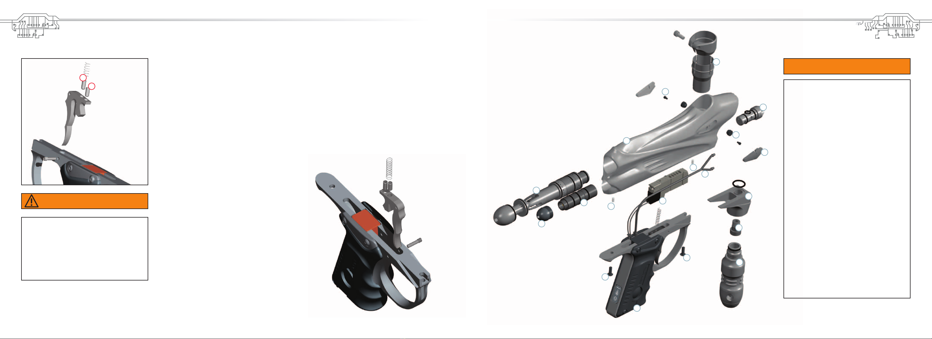
MARKER WILL NOT FIRE
-If the LED light is red, the marker will not fire because there is no ball inside the marker.
Hold the trigger for 1 second and the marker should fire. If it does not fire after holding the trigger, or if
the LED light is green and it will not fire, check your trigger settings to make sure the micro switch is actuating.
Refer to trigger adjustment page for information on setting the trigger. Last cause can be a broken solenoid wire:
check that the solenoid wire is properly connected to the board.
-Check to make sure the on/off is in the on position.
MARKER SHOOTING SLOW WHEN EYE IS ON AND BLINKING GREEN
-The eyes are not working correctly. Try cleaning the eyes. You know that they are clean when the LED turns red
when there is nothing inside the breech of the DM4.
THE EYE IS CLEAN AND ALL THE WIRES ARE CONNECTED BUT IT IS STILL NOT WORKING.
IF THE EYE IS TURNED OFF THE DM4 WILL WORK.
-Change the battery. The voltage in the battery is too low for the eye to function correctly.
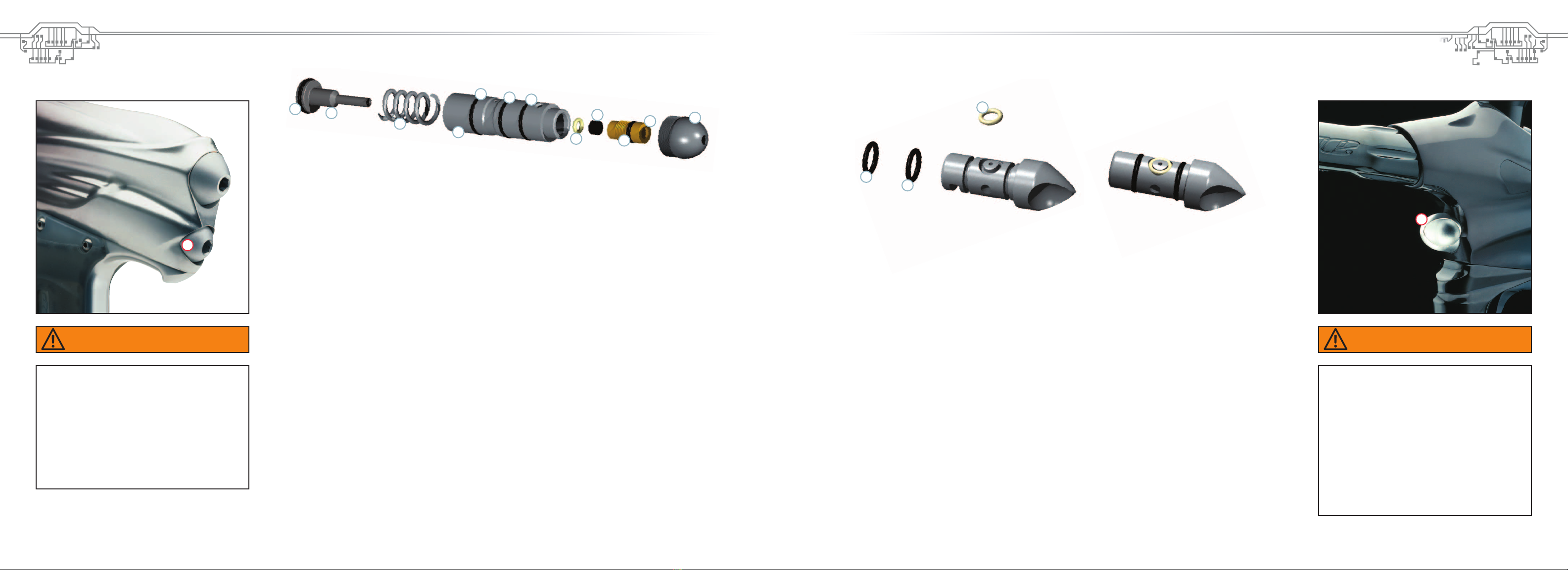
AIR LEAKING THROUGH THE BARREL
-There are three possible o-rings that cause this leak. If the leak comes through the inside of the bolt, the o-ring that
is leaking is the #13 on the top hat part of the bolt. If it’s leaking from the outside of the bolt shaft,
the bad o-ring is either the #17 on the inside of the bolt cylinder or the #20 on the outside of the bolt can.
THERE IS A LEAK FROM THE BACK HOLE OF THE BOLT
-Take out the bolt, unscrew the back part of the bolt and change the #9 o-ring on the back of the bolt shaft.
HYPER2TROUBLE SHOOTING
NO OR POOR AIR FLOW
-Check for blocked air passage in hose line or regulator. Adjustment screw may be screwed in too far.
-Seat may have excessively deep piston groove cut into it. Replace if needed.
ERRATIC VELOCITY OR SHOOT DOWN
-Piston or spring stack may be binding due to excessive dirt or lack of lubricant.
-Seat may be dirty or damaged. Clean and grease reg. Inspect and replace damaged parts as needed.
OUTPUT PRESSURE CREEPS UP
-Dirty seat or damaged piston face.
-Clean and inspect; if either is damaged, replace.
AIR LEAKS FROM SIDE VENT HOLE
-Piston o-rings may be damaged. Inspect o-rings.
-Replace if any visible nicks or cuts are found.
AIR LEAKS OUT BOTTOM OF ADJUSTMENT SCREW
-This is a safety bleed-off to help prevent over-pressurizing. De-gas the Hyper2; be sure all air is vented out of the reg. Supply air back to the regulator. The leak should stop.
If the leak persists replace the reg seat. Make sure there are no nicks or scratches on the raised ring at the bottom of the seat-retaining cavity.
INCLUDED WITH YOUR DM4
- DM4™ Marker
-Allen tool set including 5/64”, 3/32”, 1/8”, 5/32”, 3/16”, and 1/4”
-1oz. Dye Slick Lube™
-Parts Kit
-Barrel Sock
- Owner’s Manual
ADDITIONAL RECOMMENDED TOOLS
-1/16” Allen wrench
-3/8’ Allen wrench
- 5/16” Allen wrench
- Canned Air
Table of contents
Other dye Paintball Equipment manuals