Proto Rize User manual

2011-RAIL-Manual.qx_2011-RAIL-Manual 9/30/10 9:28 PM Page 1
DYE Precision, Inc.
USA 10637 Scripps Summit Ct. San Diego, CA 92131
P 858-536-5183 F 858-536-5191
GERMANY Albert Einstein Str. 2 B
77656 Offenburg, Germany
P +49 (0)781 639 349 91
ASIA No. 253, Guojhong Rd., Dali Dist.
Taichung City 412,Taiwan (R.O.C.)
P +886 (0) 4-2407-9135 F +886 (0) 4-2407-2090
dyepaintball.com
Copyright ©2016 DYE Precision, Inc.The stylized “proto” logo, the “P” logo, and MaXXed RIZE are
either registered trademarks, trademarks, or design trademarks of DYE Precision, Inc.
DYE Precision, Inc. U.S. Patent # 5,613,483, 7,594,503; 7,765,998. OTHER U.S. AND INT’L PATENTS PENDING.
Covered by one or more of the following U.S. Patents, 5,613,483; 5,881,707; 5,967,133; 6,035,843 and 6,474,326.
For a complete list of patents visit www.dyeprecision.com/patents
Made in TAIWAN DYEPAINTBALL.COM
OWNER’S MANUAL

01
W W W . D Y E P A I N T B A L L . C O M
W W W . D Y E P A I N T B A L L . C O M TA B L E O F C O N T E N T S
- IMPORTANT SAFETY INSTRUCTIONS AND GUIDELINES . . . . . . . . . . . . . . . . . . . . . . . . PAGE 02
- QUICK START UP GUIDE . . . . . . . . . . . . . . . . . . . . . . . . . . . . . . . . . . . . . . . . . . . . . . . . . . . PAGE 0 4
- RIZE
RIZE
RIZE
™BOARD SETTINGS AND FUNCTIONS . . . . . . . . . . . . . . . . . . . . . . . . . . . . . . . . . . . PAGE 0 6
- TRIGGER ADJUSTMENTS . . . . . . . . . . . . . . . . . . . . . . . . . . . . . . . . . . . . . . . . . . . . . . . . . . . PAGE 13
- ™BOLT ASSEMBLY AND MAINTENANCE . . . . . . . . . . . . . . . . . . . . . . . . . . . . . . . . . PAGE 14
- ™BOLT O-RING LIST . . . . . . . . . . . . . . . . . . . . . . . . . . . . . . . . . . . . . . . . . . . . . . . . . . . PAGE 17
- FEED NECK ADJUSTMENT . . . . . . . . . . . . . . . . . . . . . . . . . . . . . . . . . . . . . . . . . . . . . . . . . . PAGE 18
- HYPER3™REGULATOR ADJUSTMENT AND MAINTENANCE . . . . . . . . . . . . . . . . . . . . . . PAGE 20
- VELOCITY ADJUSTMENT . . . . . . . . . . . . . . . . . . . . . . . . . . . . . . . . . . . . . . . . . . . . . . . . . . . PAGE 20
- ANTI CHOP EYES AND BALL DETENTS . . . . . . . . . . . . . . . . . . . . . . . . . . . . . . . . . . . . . . . PAGE 22
- AIRPORT ADJUSTMENTS . . . . . . . . . . . . . . . . . . . . . . . . . . . . . . . . . . . . . . . . . . . . . . . . . . PAGE 2 4
- TROUBLE SHOOTING . . . . . . . . . . . . . . . . . . . . . . . . . . . . . . . . . . . . . . . . . . . . . . . . . . . . . . PAGE 25
- EXPLODED VIEW . . . . . . . . . . . . . . . . . . . . . . . . . . . . . . . . . . . . . . . . . . . . . . . . . . . . . . . . . PAGE 28
- WARRANTY AND LEGAL INFORMATION . . . . . . . . . . . . . . . . . . . . . . . . . . . . . . . . . . . . . . PAGE 29
R I Z E ™ O W N E R ’ S M A N U A L
INCLUDE D W ITH YOUR RIZE ™
RIZE ™ Ma rker
1pc Proto Barrel
A llen to ol set inc lud in g 0 .0 5”, 1/16”, 5/ 6 4 ”,
3/ 32”, 1/8”, 5/ 32”, 3/16” and 1/4 ”.
1/4 oz. DYE Slick Lub e™
Parts Kit
Barrel Plug
Owner ’s Manual
Warranty Card
9V Battery
The RIZE ™comes with the tools req uired to p erform
general maintenance and setting up .
Fo r a comp lete serv ice the following too ls are required
C- clip p liers
# 0 Phillip s head screw d river
A shar p p ic k to remove O- r ing s

W W W . D Y E P A I N T B A L L . C O MW W W . D Y E P A I N T B A L L . C O M
02 03
•Compressed gas is dang erous, do not allow comp ressed g as to
come in contact with your skin or try to stop a leak by covering it
with your hand.
•Always fit a barrel blocking device to your ™when not in use on
the field of play.
•The owner’s manual and any related warnings or instructions should
always accompany the p roduct for reference or in the event of resale
and new ownership.
•Do not point the ™marker at anything that you do not intend to
shoot.
•Do not shoot at p eople, animals, houses, cars or anything not related
to the sport of paintball.
•Do not fire the ™without the bolt screwed in comp letely.
•If you read these instructions and do not fully understand them or are
unsure of your ab ility to make necessary adjustments properly,
call DYE Precision or your local pro shop for help.
•The RIZE
RIZE
RIZE
RIZE
RIZE
RIZE
RIZE
RIZE
RIZE
RIZE
™marker is not a toy. Misuse may cause serious injury or death.
•Please read, understand and follow the directions in the ™
owner’s manual.
•Eye protection that is designed specifically for paintball and meets
ASTM/ CE stand ard s must be worn by user and persons within range.
•Recommend 18 years or older to purchase. Person under 18 must
have adult supervision.
•Always treat the ™marker as if it were loaded and able to fire.
•Do not exceed 850 psi input pressure.
•Only use .68 caliber paintballs that meet A STM/ CE standards.
•Ensure all air lines and fittings are tightened and secured before
gassing up the ™.
•Always chronograp h the ™marker before playing paintball.
•Never shoot the ™marker at velocities in excess of 30 0 feet
per second, or at velocities greater than local or national laws allow.
•Never look into the barrel or breech area of the ™when the
marker is switched on and able to fire.
WARNING
IMPORTANT SAFETY INSTRUCTIONS AND GUIDELINES
WARNING
IMPORTANT SAFETY INSTRUCTIONS AND GUIDELINES

04 05
W W W . D Y E P A I N T B A L L . C O M W W W . D Y E P A I N T B A L L . C O M
QUICK START UP GUIDE
Before playing with your new RIZE ™paintball marker there are a few
important steps to take.
STEP 1. BATTERY INSTALLATION
A . Remove three right hand side grip p anel screws with a 3/ 32” allen key.
B. Open grip panel and install 9V battery into the connector inside the frame. Start
by inserting the top of the battery into the recess and aligning the battery terminals
with the contacts on the board, then pushing the bottom of the battery fully into
place. Ensure that the battery removal ribbon leaves a small tail accessible from
under battery when installed to aid for easy battery removal. Note the markings
above the battery housing which indicate which of the board contacts are positive
and negative and install the battery accordingly.
C. Close grip p anel and tighten the three screws back. W hile closing the p anel
ob serve that no wires g et caught b etween the frame and the g rip p anel.
STEP 2. BARREL INSTALLATION
A . Screw on the barrel to the front of the RIZE ™. Make sure it thread s all the
way in and is secure.
B. Attach the b arrel plug so that it covers the tip o f the b arrel and secure
the g un.
STEP 3. LOADER INSTALLATION
STEP 4 . ATTACHING GAS SOURCE
Screw on a p reset air system into the airport located o n the b ottom of the g rip
frame.
Be sure the air system is screwed in all the way into the A irport. If there is a leak
from the airport when screwing in the air system, replace the o- ring on the p reset
reg ulator.
STEP 5. TURNING ON THE RAIL™AND CHECKING THE VELOCITY
A . Make sure you and everybody around you is wearing A STM / CE app roved
paintb all masks.
B. Press and hold the to p b utton located b ehind the g rip frame until the RA IL™
turns o n. WARNING, THE RAIL™IS LIVE. MAKE SURE BARREL PLUG IS IN PLACE
AND DO NOT POINT THE RAIL™AT ANYTHING YOU DON’T INTEND TO SHOOT.
C. F ill up the load er with .68 caliber paintb alls.
D. Shoot the RA IL™over a chrono g raph to check the velocity. If ad justment is
need ed, adjust the velocity by turning the Hyp er3™velocity ad justment screw with
a 3/ 16” allen key. In ( cloc kwise) will red uce t he veloc ity and o ut ( co un ter cloc kwise)
will increase the velocity. A fter each ad justment it takes a few shots before the
change can b e seen on the chrono g rap h. Never ad just the RA IL™to shoot faster
than 30 0 fps or what the field rules / local laws permit.
Q UI C K RE F E RE NC E
USI NG YO UR MA RK E R
Q UI C K RE F E RE NC E
USI NG YO UR MA RK E R
Tighten your loader into the adjustable feedneck using a 5/32” Allen key.
For best performance, use a force feeding motorized loader,
preferably the Rotor™ Loader.

06 07
W W W . D Y E P A I N T B A L L . C O M
RIZE ™B OA R D
SE T TI NGS A ND F UNC T I O NS
RIZE ™B OA R D
SE T TI NGS A ND F UNC T I O NS
TURNING THE RAIL™ON AND OF F
To turn on the RIZE
RIZE
RIZE
RIZE
RIZE
RIZE
™, press and hold the p ower b utton until
the LED’s turn b lue. The blue lig ht ind icates board b oot up.
After the b oo t up sequence, the LED’s will turn either RED
( no b all) or GREEN ( b all in b reach, read y to fire) . To turn the
™off, p ress and hold the p ower b utton until the LED’s
turn o ff.
NOTE: The RIZE
RIZE
™automatically switches off after 10
minutes of non-use.
FIRING THE ™
A s soon as the marker is turned on and the LED’s turn from
blue to either red or g reen, the ™is read y to fire. If there
is no ball and the LED’s are RED, yo u need to ho ld the
trig g er fo r 1 second to fo rce the ™to fire o nce. If there is
a paintball inside the breech and the LED is g reen, just p ress
the trigger to fire the marker.
LED LIGHT INDICATOR
The ™uses a super b right LED mounted on the circuit
board inside the grip frame. This lig ht is used to provid e
information to the user ab out the ™. It is mounted behind
the PROTO™logo on the left side of the grip panel.
When you turn on the marker in normal operation mode with the power b utton, the light colors
mean the following :
Blue -Bo ot sequence
Red -Breech is clear, no ball d etected inside the ™( eye is on)
Green -Ball in b reech, read y to fire ( eye on)
Blinking Red -Eye is turned off
Blinking Green -Eye failure, eye is b locked or dirty ( see ™Eye, p ag e 26)
To turn o ff the eye feature p ress and hold the b ottom b utton until the LED light starts blinking
Red indicating the eye feature is turned off.
NOTE: The eye is always activated when you turn the marker on.
When servicing your marker:
•Make sure a b arrel plug is fitted to the ™.
•Make sure your hopp er is removed from the ™.
•Make sure there are no p aintb alls in the b reech of the ™.
•A lways remove the first stage regulato r and relieve all resid ual g as
pressure from the ™ b efore disassemb ly.
•The ™ can hold a small residual charg e of g as, typ ically 2 shots, with
the first stag e regulator removed. A lways d ischarge the marker in a safe
direction to relieve this residual g as p ressure.
RIZE
RIZE
RIZE
RIZE
RIZE
RIZE
RIZE
W W W . D Y E P A I N T B A L L . C O M

08 09
W W W . D Y E P A I N T B A L L . C O M W W W . D Y E P A I N T B A L L . C O M
RIZE ™BOARD
SE T TI NGS A ND F UNC T IO NS
BOARD SETTINGS AND CONF IGURATION MODE
There are five settings yo u can alter o n the RIZE ™board with
the DIP switches inside the g rip frame ( see figure 1) :
ABS A nti Bo lt Stick.
Trigger Sensitivity This setting adjusts the d elay
between two trigg er pulls.
Dwell This is the time the solenoid is
activated for.
Rate Of Fire This setting is for ad justing the
maximum rate of fire
Firing Mode This is the firing mod e the RIZE ™uses.
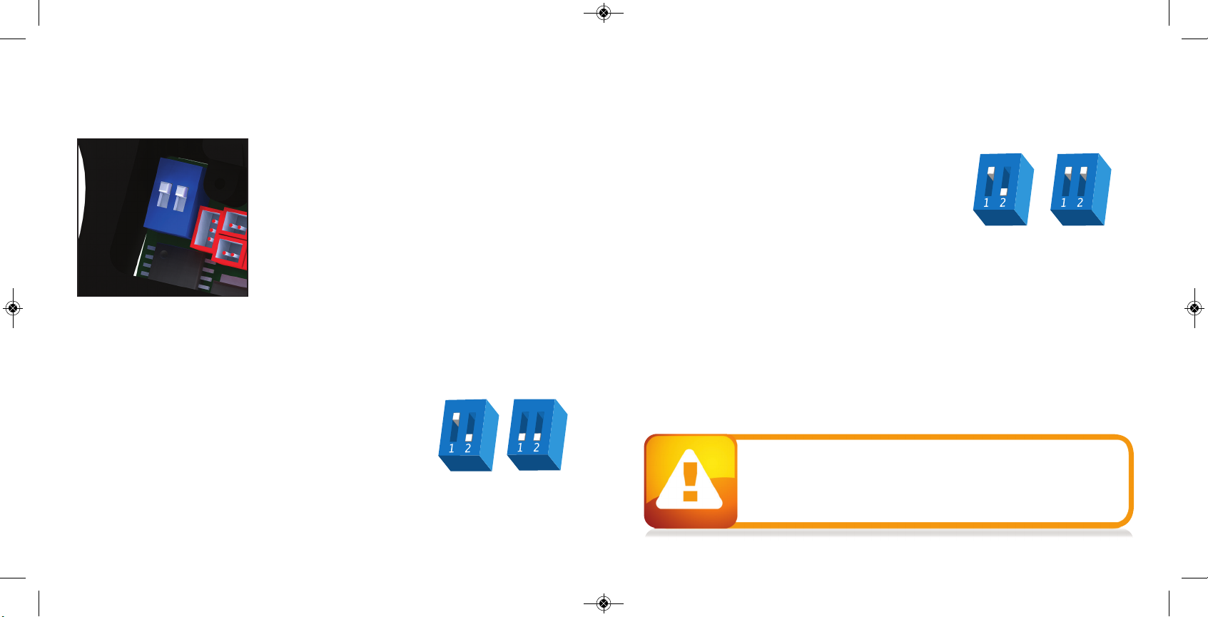
There are two DIP switches mounted o n the b o ard o f the RIZE ™( See fig ure 1) . The first one is
used for the A BS setting and the second one is used to access a config uration mo d e which
changes the other four settings.
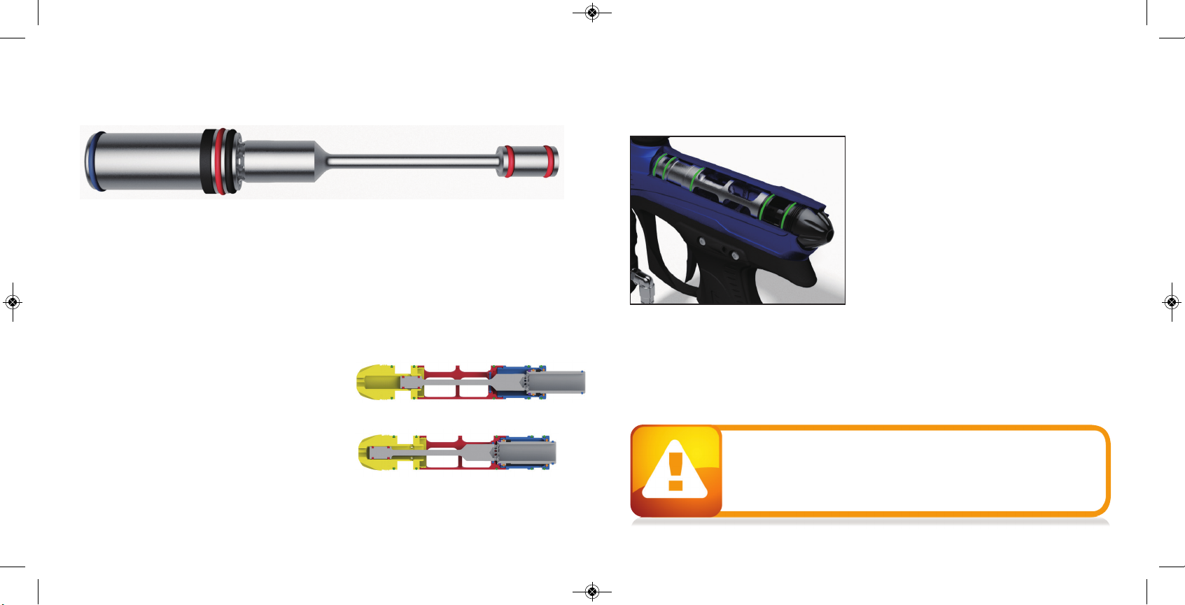
Anti Bolt Stick -W hen A BS is activated , the dwell is increased after
15 second s of no n- use for the next sho t fired . This help s to prevent
bolt- stick, b ut may result in hig her velocity for the first shot.
FIGURE 1
ABS ON
(DEFAULT)
ABS OF F
CONFIGURATION MODE - The following settings can only b e
modified in configuration mode. To activate the co nfiguration
mode, turn yo ur marker off and set DIP switch 2 to the ON
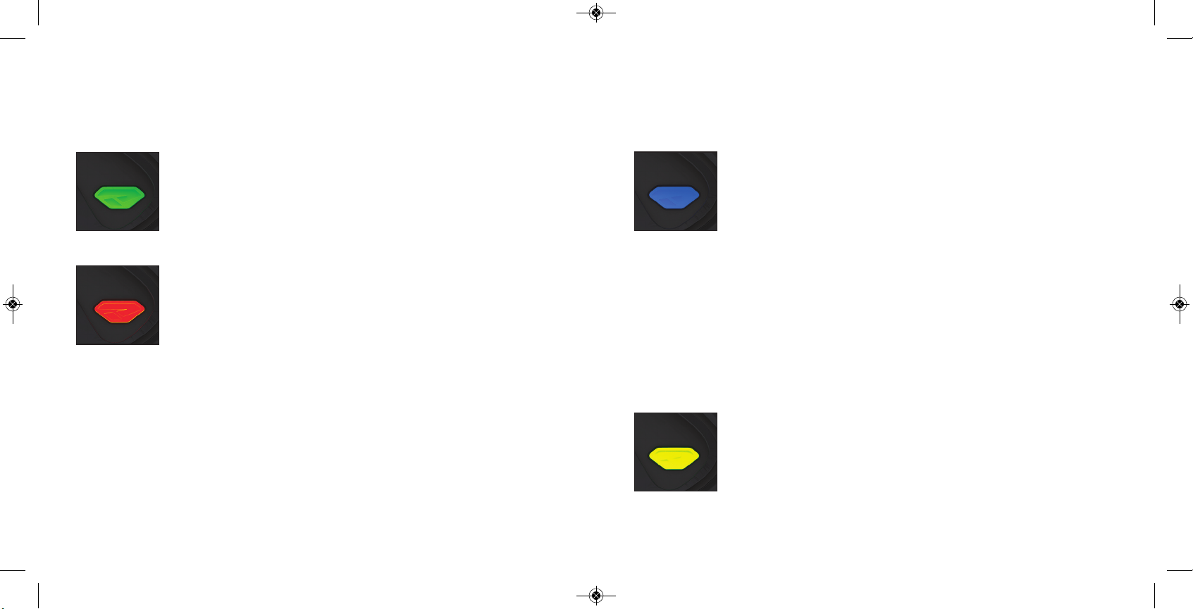
position. Next, turn yo ur marker on. The LED's cycle throug h
all colors for one seco nd to ind icate that yo u have entered
the config uration mod e.
To cycle throug h d ifferent settings, p ull and release the trigg er.
Config uration mode has 4 settings that can b e chang ed.
TO CHANGE A VALUE OF A SETTING
1. While in the config uration mo d e, choose the setting yo u wish to chang e by p ulling the trigger
to cycle throug h d ifferent op tions.
2. W hen the LED indicates the color of the setting you wish to chang e, p ull and hold the trig g er
until the LED starts to flash.
3. The LED will flash as many times as the previous setting was and it will then turn o ff. Now pull
the trigg er as many times as you wish the new setting to b e. Note: You must enter a value at this
point, if yo u d o not wish to alter the setting then re- enter the prev ious value.
4. W hen d o ne, the LED will cycle throug h all the co lors again to indicate setting was saved and
turn b ack to g reen. You can now chang e ano ther setting o r q uit the configuration mod e.
5. To exit configuration mode, set DIP 2 to the off p osition.
NORMAL
MODE
CONF IGURATION
MODE
RIZE ™BOARD
SE T TI NGS A ND F UNC T IO NS
•The RIZE™ is not water resistant. Excess moisture can cause damage
to electronic parts.
•Keep the board and all electrical components clean of dirt, paint and moisture.
•To clean the board, use canned air. If a more aggressive cleaning method
is needed, lightly scrub the components with a soft, dry brush.
Heavy scrubbing will damage the board.

10 11
W W W . D Y E P A I N T B A L L . C O M W W W . D Y E P A I N T B A L L . C O M
RIZE ™BOARD
SE T TI NGS A ND F UNC T IO NS
BLUE - Rate Of Fire (ROF ) Values 1 - 30
The ROF setting is used to set the maximum rate of fire of the RIZE ™.
The values d o not correspo nd d irectly to a certain Balls Per Second
( BPS) value. Yo u will need to use the tab le below to locate yo ur
desired maximum ROF setting.
The factory setting is 3(10 .0 bps).
Increasing ROF too high will increase probability of ball b reakage.
If this occurs decrease ROF setting.
YELLOW - Firing Mode Values 1 - 4 (default 1)
This setting chang es the firing mode of the RIZE ™. Default is
semiautomatic. In the semiautomatic mod e, one trigger p ull
shoo ts out o ne p aintb all. The PSP mode and the Millennium
mode fo llow the rules of the p aintb all tournament series.
Value 1 - Semi- auto matic Mod e
Value 2 - Millennium Mode
Value 3 - PSP Mod e
Value 4 - Full auto with first shot safety feature
19.80 BPS
29.90 BPS
310.0 BPS
410.10 BPS
510.20 BPS
610.30 BPS
710.41 BPS
810.52 BPS
910.63 BPS
10 10.75 BPS
11 10.86 BPS
12 10.98 BPS
13 11.11 BPS
14 11.62 BPS
15 11.76 BPS
16 11.90 BPS
17 12.0 4 BPS
18 12.19 BPS
19 12.34 BPS
20 12.50 BPS
21 12.65 BPS
22 12.82 BPS
23 12.98 BPS
24 13.15 BPS
25 13.33 BPS
26 13.51 BPS
27 13.69 BPS
28 13.88 BPS
29 14.0 8 BPS
30 14.28 BPS
RIZE ™BOARD
SE T TI NGS A ND F UNC T IO NS
GREEN - Trigger Sensitivity Values 1 - 20 (factory default 5)
Trigg er sensitivity is the amount of time that the trig g er has to be
released b efo re the next trigg er pull is allowed . In some situations
with too low of a value, the RIZE ™can register more trig g er p ulls
than what was actually pulled . This can cause the RIZE ™to shoot full
auto, even in semi- automatic mod e. To fix this, ad just the trig g er
sensitiv ity setting higher.
RED - Dwell Values 1 - 50 (factory default 40 )
Dwell is the amount of time that the so lenoid will be activated.
Fo llow these steps for the b est way to set your d well:
•Remove load er and any p aintb alls from the RIZE ™marker.
•With the d well set at 20 , start increasing the value until the marker
begins to fire.
•When you reach the setting where the marker b egins to fire, g et
some paint and a load er and g o to a chronograp h.
•Increase the d well until you see no increase in the velocity.
This is the op timal d well setting to b e used.
NOTE: You cannot turn your marker off with the power button
when the marker is in configuration mode. You must first set DIP
switch 2 to the OF F position.

12 13
W W W . D Y E P A I N T B A L L . C O M W W W . D Y E P A I N T B A L L . C O M
TRIGGER
ADJUSTMENT
RIZE ™BOARD
SE T TI NGS A ND F UNC T IO NS
BATTERY
The 9V battery will last fo r about 12,0 0 0 shots. Please b e aware that there are sub stantial
differences in p erformance b etween d ifferent b rand s of batteries. Use of high q uality alkaline or
lithium io n b atteries is recommended for maximum b attery life. If yo u p lan not to use your marker
for a long period of time ( a month) , it is recommended that you remove the b attery from the
marker. When the b attery voltage starts to go to o low, the marker will not fire with every trig g er
pull. For to urnament use, it is recommend ed to change the b attery for each tournament.
CHANGING THE BATTERY
The battery is housed on the right side of the g rip frame. To access the b attery, remove the three
screws holding the right side g rip p anel down. Use a 3⁄32” allen key. When inserting a new battery
notice the + and - marks on the b oard. The p ositive lead of the 9V b attery g oes to the left and the
neg ative lead to the right.
NOTE: If the marker will not function with the eye on, there is a good chance the battery needs
to be changed.
•A low battery will not b e able to power both the ACE eye and the trigg er
switch, causing ACE eye failure.
•If the b attery is low, the marker will not fire with every trigg er p ull.
•Be sure the trigg er is not ad justed to the point where it is too sensitive
and may cause accid ental discharge of the marker.
•Removing the trigg er spring will cause premature wear on the microswitch,
resulting in failure.
•Be sure you do not pinch the wires between the frame and body when
reattaching the frame to the body.
ADJUSTING YOUR TRIGGER
The Trigg er’s fo rward travel and over travel are fully
ad justable so that the user can fine- tune the trigg er to
his/ her exact p reference.
To adjust the trigg er an .0 50 ” and 5/ 6 4 ’ A llen key is
need ed. There are two ad justment screws located o n the
trig g er.
The up p er screw o n the front of the trigger co ntrols the
forward travel ( 1) and requires a 5/ 64 ” allen wrench to
ad just. Screwing it in will incease the trigg er’s leng th of
pull. Note: If this screw is screwed too far out, the switch
will be d epressed all the time causing the RIZE ™to fire
once immediately after turning it on and not firing after that! ( Fig. 1) .
The lower screw on the front of the trigg er controls the over travel ( 2) and req uires the .0 50 ” allen
wrench to ad just. By turning this screw you can ad just how far b ack the trigg er will travel. Note: If
this screw is adjusted too far, the trig g er will not be allowed to travel far enoug h to d epress the
switch and the marker will not fire.
The trigger sp ring used to return the trigger is located insid e the frame. It is not sug gested to
remove this sp ring as it will cause excess wear o n the microswitch and cause trigger b o unce.
1
2
FIGURE 1

14 15
W W W . D Y E P A I N T B A L L . C O M W W W . D Y E P A I N T B A L L . C O M
The RIZE RIZE
RIZE
RIZE
RIZE
RIZE
RIZE RIZE
RIZE
RIZE
RIZE
RIZE
™BOLT is the main comp onent of the ™ marker. In order to achieve the best
possible performance of the RA IL™it is essential that the ™BOLT is kept clean, well lubed
and in good working ord er.
The ™BOLT should be cleaned and re-lubed after each day of use.
There are 4 p arts in the ™ BOLT kit that mount tog ether as one unit. To remove the ™
BOLT fro m your ™, use a 1/ 4 " allen key and turn the Back Cap out 2 full turns counter
clockwise. Now pull out the complete RA IL™b o lt kit from the ™.
To d is- assemb le the ™BOLT kit you unthread the front most part called the Can and the
Manifold from each other. Then pull out the actual moving bolt from insid e these pieces. Notice
that to sep arate the Can and the Bolt yo u need to remove
the bolt tip O- ring b efore the bolt is able to slide through
the Can.
HOW DOES IT WORK
A ir is supplied into two p oints on the ™ BOLT. In the
back air is routed through the Back Cap and Manifold
and fills up the supply chamber around the Manifold. In
the front air is routed throug h the soleno id into the Can.
This air pushes against the Sail on the Bolt, which keeps
the bolt in the b ack position.
FORWARD POSITION
RIZE ™BO LT
A SSE MBLY A ND MAI NTE NA NC E
RIZE ™BO LT
A SSE MBLY A ND MAI NTE NA NC E
When the ™ is fired the solenoid is actuated
and the air inside the Can is exhausted out. The
force created by the air inside the sup p ly chamber
causes the b olt to start moving forward. Once the
bolt has moved ab out half way forward, the tail of
the bolt closes the inp ut into the sup p ly chamber.
Once the Bolt reaches the forward p oint, the valve
of the ™ Bolt is op ened and air insid e the
supp ly chamb er goes throug h the Bolt and fires
the p aintball. After this the solenoid is de-
activated and gas is supp lied throug h the
solenoid b ack into the Can. This causes the Bolt
to return to the back position and the supp ly
chamb er to b e re- charg ed .
When servicing your marker:
•Make sure your hopper is removed from the marker.
•Make sure there are no paintballs in the breech of the marker.
•Always remove the air supply and relieve all gas pressure in the marker
before disassembly.
•When using the marker in temperatures below 50° Fahrenheit it may be
necessary to lube the RAIL™ bolt more frequently.
BACK POSITION

16 17
W W W . D Y E P A I N T B A L L . C O M W W W . D Y E P A I N T B A L L . C O M
RIZE ™BO LT
A SSE MB LY A ND MA INT ENA NC E
67
1 1 1
4
1
2
1
4
10 20 N 70
20 17 N 70
30 15 N 70
40 14 N 70
5
6
7
009 N 70
0 13 x2mm N 9 0
RAIL™BOLT O-RING LIST
RIZE ™BO LT
A SSE MB LY A ND MA INT ENA NC E
009
3
MAINTENANCE
If the RIZE ™
BOLT is not kept clean
and well lubed, you will either start
seeing erratic velocity, leaks or over
long period of time, physical
damage to the RIZE ™
BOLT
components.
For troubleshooting leaks and other bolt problems, consult the
troubleshooting section at the end of this manual.
55
Bolt Front Bumper
The basic maintenance for the RIZE™ BOLT is to clean all surfaces of
dirt, broken paint or other debris, check for any wear and tear on
the O-rings and changing them if needed, and finally applying
a thin coat of DYE Slick Lube on all surfaces. Before installing
the RIZE™ BOLT back to the RIZE™ marker check that the
bolt moves freely without a lot of friction and
make sure all pieces are threaded
together snugly!.

LOA DERS A ND F EED NEC K
LOADERS AND FEED NECK
To achieve the maximum
perfo rmance of the RIZE ™ you will
need to use a motorized loader that
force feeds p aintb alls into the
RIZE ™ mar ker, p refera bly the
Rotor™Load er. Using a slower
motorized load er or a non-
motorized load er will work, but the
rate of fire and perfo rmance will b e
red uced.
TO FIT A LOADER ONTO THE
RIZE ™:
1. To fit a loader onto the RIZE™,
tighten yo ur load er into the
ad justable feed neck using a 5/ 32”
A llen key.
2. Loader should now be held in with a snug fit.
3. There is no maintenance need ed fo r the feed neck
besid es keep ing it clean of broken paint, d irt and
debris.
A IR / NI TR O GE N
AIR / NITROGEN TANK OPTIONS AND INSTALLATION
The RIZE ™ with Compressed air and Nitrog en air systems
such as the DY E Throttle® air system and will also
work with CO2. Do not use any other comp ressed
gas. The outp ut pressure from the air system has
to b e b etween 40 0 – 850 psi. If yo u are using CO2
it is essential that the tank is fitted with an anti-
sipho n tub e to p revent liq uid CO2from
entering the RIZE ™.
To install an air system, screw the tank into
the airp ort all the way as far as it will g o.
To remove the air system screw out.
There will be gas leaking for a few
seco nd s while you screw the air system
out. Notice that even with the air
system removed there can b e g as
insid e the RIZE™ and it can still fire
a p aintb all. A lways t reat th e
marker as being live and never
point it to anything you d o n’t
intend to sho ot at!
18 19
W W W . D Y E P A I N T B A L L . C O M W W W . D Y E P A I N T B A L L . C O M

HYP ER3 ™I N- L I NE R E GUL ATO R
A DJUSTME NTS A ND MA I NT ENA NC E
HYPER3™REGULATOR DIS-ASSEMBLY INSTRUCTIONS
Before p erforming maintenance on the Hyp er3™reg ulator, ensure that the RIZE™ is co mp letely
degassed and then unscrew the Hyp er3™fro m the RIZE ™marker.
To d isassemble the Hyp er3™regulato r you will need a C- clip tool or a strong p ick. Remove the C-
clip from the b ottom of the Hyp er 3 reg. Next, unscrew the Brass seat housing from the b od y
with a 3⁄16 ” A llen key.
To chang e the seat, p ull out the old seat from the housing with a sharp ob ject. Insert the new seat
in place and push it down with a flat o b ject. Notice that it takes about 20 0 0 sho ts for the seat to
perfectly sit into the seat housing. This is called the break in p eriod for the reg ulator. Rememb er
to ap ply lube to the 0 10 on the b rass reg seat ho using b efo re re- assembly. F urther d isa ssembly to
service the top section of the Hyper3™should be p erformed by a trained Tech.
C-CLIP
SEAT HOUSING BODY
0 14 BN0 70
REGULATOR SEAT
TOP CAP
VELOCITY ADJUSTMENT
The velocity of the RIZE™ is adjusted by ad justing the input
pressure into the RIZE ™. This is controlled with the Hyp er3™
reg ulator. The Hyp er3™on the RIZE ™is factory set to 140 p si which
will give yo u a velo city of ab out 285 F PS ( Feet p er Second) .
A 3⁄16 ” allen key will be need ed fo r this o p eration. Turning the
ad justment screw in ( clockwise) will d ecrease the p ressure, and out
( co unterclockwise) will increase the p ressure. To ad just the
velocity:
1. Make sure you and everybod y around you is wearing A STM/ CE
ap p roved p aintb all gogg les.
2. Shoot the RIZE ™over a p aintb all chrono g raph.
3. To lower the velocity turn the Hyper3™ad justment screw in. To
increase the velocity turn the screw out. Only turn the screw a
quarter turn at a time and sho ot over the chronog rap h ag ain.
Notice that a few sho ts are need ed b efore the change can b e
seen on the chrono g rap h.
MAINTENANCE
Fo r the RIZE™ to function prop erly, it is essential that the input
pressure into the marker stays consistent at all times. The general
maintenance need ed for the Hy p er3™reg ulator is to keep it clean
of d irt and d ebris at all times. A mo re extensive service should b e
perfo rmed every 12 months by a trained Tech or if the o utput
pressure of the regulator b ecomes inconsistent. This can be seen
as inconsistent velocity and verified with a reg ulator tester ( so ld
sep arately) . Notice that the Hyp er3™has a break in p eriod o f
ab o ut 20 0 0 shots b efore it achieves the best performance.
HYP ER3 ™I N- L I NE R E GUL ATO R
A DJUSTME NTS A ND MA I NT ENA NC E
2011-RAIL-Manual.qx_2011-RAIL-Manual 9/30/10 9:28 PM Page 23
20 21
W W W . D Y E P A I N T B A L L . C O M W W W . D Y E P A I N T B A L L . C O M

22 23
W W W . D Y E P A I N T B A L L . C O M W W W . D Y E P A I N T B A L L . C O M
ANTI C HO P EYES/ BALL D ETENTS
MA I NT ENA NC E A ND C H ANGI NG
ANTI CHOP EYES
The A nti Chop Eye ( ACE) system will
prevent the RIZE ™from cho p p ing p aint
by not allowing the marker to fire until
a ball is fully seated in front o f the b olt.
The eyes use a b eam across the
breech. On one sid e there is a
transmitter, and on the o p posite sid e a
receiver. In order for the marker to fire
with the eyes turned on, the sig nal
between the two eyes must b e b ro ken.
After every sho t, before the next ball
drop s in the b reech, the eye
transmitter and receiver must see each
other. If the eyes are dirty and cannot
see each o ther b etween shots, the LED
on the board will start blinking green.
This means that the eyes are d irty. This is an extremely reliab le system as long as the eyes are
kep t clean. The mo st common reason for d irty eyes is broken p aint. If the eyes beco me d irty, the
marker will d efault to a red uced rate of fire to p revent chop ping. If this hap p ens d uring game play,
you can by p ass this by turning the eyes o ff. Clean the eyes as soon as p ossible.
NOTE: IF THE BATTERY IS LOW, THE MARKER MAY ACT AS IF THE EYES ARE DIRTY OR NOT
FIRE AT ALL. IN THIS CASE, REPLACE THE BATTERY.
SELF CLEANING EYE FEATURE
ANTI C HO P EYES/ BALL D ETENTS
MA I NT ENA NC E A ND C H ANGI NG
If this does no t clear the b lockag e use a swab to clean the insid e of the breech.
Fo r a more thorough cleaning, p ull the Eye Pip e with the b all d etents o ut the front of the b reech.
With the Eye Pipe out use a swab to clean the breech. This sho uld be enoug h to clean the eye
system. If the system need s further cleaning, p ull out the eye carrier and eye wires through the
feed neck. To prevent d amag ing the eye wires, it is best to remove the frame and d isconnect the
eye wires from the b oard . Use a soft rag and q- tips to clean off any b uilt up p aint or g rease.
When re-assemb ling the eye guard system, work backward s from disassembly. The Eye Pipe is
keyed into the breech and can only g o in one way.
NOTE: REGULAR EYE CLEANING IS RECOMMENDED EVEN IF NO PAINT IS BROKEN. CLEAN
THE EYES EVERY TWO MONTHS OR 10 ,0 0 0 SHOTS TO ELIMINATE ANY BUILT UP DIRT.
EXCESS GREASE CAN BUILD UP IN F RONT OF THE EYES. REMEMBER TO CHECK F OR THIS
AFTER GREASING THE BOLT AND CYCLING THE MARKER A FEW TIMES.
CHANGING BALL DETENTS
The b all detent system is clip ped to the outside of the Eye Pipe. The b all detent system need s
little or no maintenance. The detents should easily flex out of the way with little force, such as a
paintb all moving p ast. If you are experiencing d oub le feeding or cho p p ing, check the cond ition of
your b all d etents with yo ur finger to make sure they are not b roken, stuck in the up o r d own
position, and that they move in and out of the breech freely. If excessive broken p aint or d irt has
jammed your b all detents, remove the Eye Pipe/ detent system from the front of the RIZE ™and
unclip the d etents for a tho rough cleaning. Reinstall the d etents, and Eye Pipe after you have
sufficiently cleaned the d etents and b reech.
Be careful not to over- flex the d etents when hand ling them. Excessive flexing could break or
damag e the detents.
The RIZE™ is equipped with a self-cleaning eye feature. There is a clear polycarbonate sleeve
mounted inside the breech of the gun covering the eyes. When the bolt tip O-ring passes
through the Eye Pipe, it sweeps off any dirt, grease or paint that could be blocking the
eyes. Normally it is enough to just fire the RIZE™ to clean anything blocking the eyes.

24 25
W W W . D Y E P A I N T B A L L . C O M W W W . D Y E P A I N T B A L L . C O M
AIRPORT ADJUSTMENT AND MAINTENANCE
The location of the airp ort ad ap ter can b e moved
ap p roximately 11⁄4 ” back or forward from the stock
position to fit your individual preference. To change the
position:
1. Op en the three, right side grip panel screws with
a 3⁄32” A llen key.
2. Remove the 9V b attery by pulling on the rib b o n.
3. Using a 3⁄32” A llen key, loosen the airp ort locking
screw until airport slides b ack and forth loosely.
4. Set the airp o rt to the d esired p o sition.
5. Tighten airp ort locking screw, install the 9V b attery
and tig hten the three grip p anel screws.
When screwing the air system into the airp ort, always check that the threads on the air system and
the airport are clean and not worn out. If you think the thread s are not in good co nd ition, contact
DYE Precisio n or a professional store before screwing in the air system.
The RIZE
RIZE
RIZE
™airport will work with b oth 30 0 0 psi,
450 0 psi air systems and CO2tanks fitted with an
anti -sipho n. It is recommended that you use the
DYE Throttle® air system, althoug h the airport on
the ™is designed to work with mo st other air
systems. A lways ensure that the o- ring at the top
of the preset regulator is in good co nd ition before
connecting it to the ™marker.
AIR LEAKS
AIR LEAKING FROM THE AIRPORT
•Check the o- ring on the air system. If need ed
change the O- ring and try ag ain. The O- ring
normally used is # 15 but so me manufa cturers
mig ht use a different size. Consult the manual
of the air system you are using
AIR LEAKING FROM THE HYPER3™REGULATOR
•First locate the p o sitio n o f the leak.
•F or d isa ssem b ly i nst r uc tio ns c on sult t he
techn ic al sect io n u nd er Hy p er 3™
r eg u la to r.
•If the leak is coming from the b otto m of the
reg ulato r y ou will n eed t o d i sassemb le t he
reg ulato r a nd c han g e t he # 0 10 O- r ing a nd
the seat o n the b rass sea t retainer mounted
insid e t he H yp er3™reg ulat or.
•If the leak comes from the sma ll hole in the
mid d le o f t he reg ula to r t her e a re t wo p o ssib le
O - ring s. C han g e t he # 0 15 O - ring o n t he
p isto n a nd t he # 0 0 7 u re than e O - ring in sid e
t he b o d y o f the r eg u la to r.
•If the leak is fro m the to p of the reg ulator
chang e the # 0 14 O - ring on the outsid e
of t he cap .
•Change the # 0 14O- ring on the top cap o f
the Hyper3™and ap p ly a small amount o f lube
to the O- ring.
AIR LEAKING BETW EEN BODY AND F RAME
•A leak b etween the bod y and the frame can b e
caused by a coup le of things.
•First Check that the Hyper3 reg is not set to o
hig h or too low.
•If ab ove doesn’t help , remove the frame from
the RIZE ™and check the hose connections
between the solenoid and the hose fittings.
•Last p ossib ility is that o ne of the hose fitting s
is leaking . Gas up the RIZE ™without the frame
attached and try to locate the exact point of
leakag e. If the leak is coming from o ne of the
hose fittings, remove the screw, check and
rep la ce a ny d a ma ged o - ring s a nd re- attach
screw to the b od y.
AIR LEAKING FROM BACK OF THE RIZE ™
•Check that the bo lt kit is tightened all the way
into the ™. If the bo lt kit is loose, it will
start to leak.
•If ab ove does not solve the leak, remove the
bolt kit and change the # 0 20 O- ring o n the
back cap of the bo lt kit. A lso chang e the two
# 0 0 9 O- rings located on the tail o f the bolt.
Lube well and re-insert the b o lt kit into the
™. Check b o lt kit b reak down picture on
p ag e 19 fo r O - ring lo ca tio ns
AIR LEAKING FROM FRONT OF THE
RIZE
™
•Remove the Bo lt kit from the marker and
change the # 0 17 O- ring located insid e of the
Can and the # 0 14 O- ring lo cated insid e
the Manifold. Lube well and re- assem
TR O UBL E SHO OTI NG GUI D EA IR PO R T
A SSE MBLY A ND MAI NTE NA NC E
RIZE
RIZE
• If above doesn’t help, try changing the

26 27
W W W . D Y E P A I N T B A L L . C O M W W W . D Y E P A I N T B A L L . C O M
•Make sure there is a trigger spring insid e
the frame.
ERRATIC VELOCITY / RIZE ™WON’T FIRE
RIZE ™FIRES BUT BALLS ARE DROPPING OFF
OR NOT EVEN COMING OUT OF THE BARREL
•Make sure the b attery is g o od .
•Raise the d well to factory level ( 4 0 ) .
•Make sure bolt is well lubed and moves well.
If there is too much friction in the Bolt, it will
cause the RIZE ™to shoot d own.
•Make sure air system is screwed in all the way.
FIRST SHOT IS TOO HIGH
•Change the Seat insid e the Hyper3™reg ulator.
For disassemb ly instructions consult the
technical section.
•Try turning off the ABS feature by turning DIP
# 1to the o ff p osition.
VELOCITY IS NOT CONSISTENT
•Make sure the p aintballs you are using fit the
barrel g o od and are consistent in size.
The sto ck b arrel with the RIZE ™is .688 size.
You should b e ab le to blow the p aintb all
through the barrel b ut they should not roll
through the barrel on their own.
•Remove the bolt kit and re- lube it. Chang e any
O- ring s c ausing a lo t o f fr iction. Ma ke sure
# 014 O- ring in b o lt tip is in p lace and in
good condition.
TR O UBL E SHO OTI NG GUI D E
•Raise the d well.
•Change the battery.
•Check that the Hyp er3™reg ulator is working
correctly and that the p ressure is co nsistent.
A sep arate reg ulator testing tool is availab le
for this. If need ed, d isassemble and chang e
worn out O- ring s in the Hyp er3™regulator.
OTHER CATEGORIES
DOUBLE FEEDING
•If you get two balls firing at once change the
ball detents by removing the Eye Pip e,
rep lacing the orang e d etent clip and
reinstalling the Eye Pip e.
BREAKING PAINT
•Make sure you use high quality p aintballs and
that they are stored accord ing to the
manufacturers instructions.
•Check that # 14 O- ring o n bolt tip is in place
and in good condition.
•Make sure your loader is working goo d and
that the rate of fire is not set higher than the
maximum feed rate of the loader.
•Check that the b arrel you are using is not too
tight for the paintballs you are using .
•Check the cond itio n of the b all detents.
TR O UBL E SHO OTI NG GUI D E
# 0 20 O- ring s located outsid e o f the Can.
Lube well b efore re- inserting b olt kit.
PROBLEMS W ITH ELECTRONICS
RIZE ™WON’T TURN ON
•Make sure b attery is new and well charged.
•Check that b attery is making contact with the
board terminals insid e the RIZE ™.
•Make sure there is no dirt or d ebris b locking
the button fro m being p ressed.
RIZE ™W ILL TURN ON / OF F BY ITSELF OR THE
EYES WILL TURN ON / OFF BY THEM SELVES
•Both o f these prob lems are caused b ecause
the button( s) are pressed all the time.
•Remove board from the frame by removing the
grip panel on the left hand side, disconnecting
the cab les and pulling the board out. Carefully
remove the two buttons and clean them well.
•Re- assemb le and t est. If p ro b lem s p er sist,
contact authorized service center for bo ard
rep lacement.
EYES W ILL NOT WORK, LED KEEPS
BLINKING GREEN
•First chang e the b attery. The eyes are no rmally
the first thing to stop working when a battery
is d y ing.
•Next try to clean the eyes. See p ag e 22
for d etails on how to remove the Eye Pipe and
To test if the eyes work make sure there
is nothing insid e the b reech and that the b olt is
in the back p osition. Turn on the RIZE ™, the
light should be red after the b oot up sequence.
If it is, the eyes are working .
•Check that the eye wire is properly connected
to the board .
•If nothing ab ove helps contact a store or DYE
Precision fo r eye rep lacement.
SOLENOID W ILL NOT ACTIVATE / TRIGGER
NOT WORKING
•Check that the trig g er ad justment is not set so
that the micro switch cannot activate.
You should hear a small click when pulling
the trigg er.
•If the RIZE ™fires once when turned on b ut not
after that your trigg er is set so that the micro
switch is always activated. Re-adjust the trigger.
•Change the battery if yo u are not positive
about it’s charge.
•Check that the solenoid and cap acitor cables
are attached to the b oard and to the rig ht
connectors ( solenoid should b e attached to
the connector that is colored b lue) .
TRIGGER BOUNCE / RAIL™SHOOTING MORE
THAN ONE BALL PER PULL IN SEMI AUTOMATIC
MODE
•Raise the trigger sensitivity level in the
configuration mod e.
•Check that the trigg er is not ad justed too short.
clean the eyes.

28 29
W W W . D Y E P A I N T B A L L . C O M
1
5
3
8
7
14
17
16
13
11
16
10
6
12
9
4
2E XP LO D ED VI E W
1 Clamping Feed Collar
2 Feed Neck Knob
3 Feed Neck
4 Ball Detent
5 Eye Pipe
6 Hy p er3™
7 “ACE” Eye
8 So lenoid
9 Front F rame Screw
10 Ultralite Frame
11 Rear Frame Screw
12 RIZE ™ Bo lt
13 RIZE ™ Bo d y
14 ASA Screw
15 A irp ort
16 A SA
17 So lenoid screws
PARTS LIST
WARRANTY
DYE Precision, Inc. warra nts for o ne year to the initial retail p urchaser, fro m t he initial d ate o f
purchase, that the paintb all marker a nd reg ulato r a re free from defec ts in materia ls and
workmanship , subject to the req uirements, d isclaimers and limitat ions of this warra nty. Disp osab le
parts, normal maintenance a nd standard wear and tear parts such as b atteries, O - ring s and seals are
not covered under warranty. The solenoid and electronic compo nents on the ma r ker a re covered
und er warranty for six mo nths. This warranty d oes not cover scratches, nicks, imp rop er disassembly,
imp rop er re- a ssemb ly, misuse, neg lect o r imp rop er storag e. Mod ificatio n to t he p roduct will void the
warra nty. The only autho rized lub rica nt fo r the marker is Slick Lube™. Use of any o ther lubricant will
void your war ranty. This warra nty is limited to rep air o r rep lacement of d efective p arts with the
customer to pay ship p ing co sts. Warranty ca rd and proof of purchase must be sub mitted to DYE
Precision for warranty to be in effect. This warranty is not transferable. This warranty d oes not cover
p er forma nc e. Paintb al l m ark ers a re n on- r efu nd ab le.
TECHNICAL SUPPORT
Our Technical Sup port Dep artments are open Monday through Friday.
DYE Precision, Inc. can be reached at 858-536 - 5183 ext.277 fro m 9 a m to 5pm PST.
DYE Europe can be rea ched at +44 ( 0 ) 20 - 8 6 4 9- 6330 from 9am to 5pm GMT.
DY E A sia c an b e rea ch ed a t 8 86 ( 0 ) 4 - 24 0 7- 9 13 5 fro m 9 am t o 5p m GMT +8 hour s.
Add itional supp o rt and international co ntacts are availab le throug h our web site,
www.dyep a intb all.com.
DISCLAIMER
The sp ecificatio ns & photographs in this ma terial are for information and genera l g uid ance p urposes
only. Our p ro ducts are co ntinually upd ated a nd chang es may b e mad e to sp ecifica tion, desig n o r
app earance fro m time to t ime. These are sub ject to change without notice. Contents of box may
therefo re vary fro m owner’s manual. For details of chang es in d esig n, sp ecificatio n o r app earance
consult your local d istrib utor o r dealer. The F USE™BOLT, RIZE ™, Hyper3™and Slick Lube™a re
registered trademarks. Design rig hts, co p y r ights and a ll o ther rig hts reserved .
A ll p atterns, d rawings, p hoto graphs, instructions o r manuals remain the intellectual p rop erty
of the ma nufacturer.
DYE Precision, Inc. U.S. Patent # 5,613,483, 7,594,50 3; 7,76 5,998. OTHER U.S. A ND INT ’L PAT ENT S
PENDING. Covered by one or more of the following U.S. Patent s, 5,613,483; 5,881,707; 5,967,133;
6,035,843 a nd 6,474 ,326 . A ll rights will be strictly enfo rced.
RA IL™WA RR ANTY INF O RMATI O N
WA R R ANT Y A ND L E GA L I NF O R MATI O N
15
17
Table of contents
Other Proto Paintball Equipment manuals