Nippa WB18 Installation guide

Sauna StovesSauna Stoves
Sauna StovesSauna Stoves
Sauna Stoves
& Heaters& Heaters
& Heaters& Heaters
& Heaters
Since 1930Since 1930
Since 1930Since 1930
Since 1930
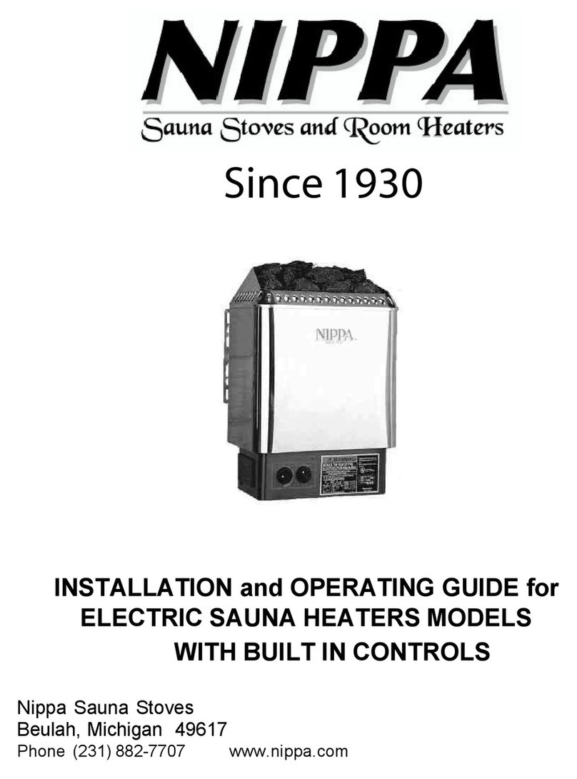
INSTALLATION and OPERATING GUIDE for
SAUNA HEATER MODELS
WB18 WB22 WB24
WC18 WC22 WC24
Nippa Sauna Stoves
Beulah, Michigan 49617
Phone (231) 882-7707 www.nippa.com

Congratulations
On your purchase of a NIPPA wood burning sauna heater
Undoubtedly, you have given much consideration into your decision to buy a NIPPA sauna
heater and everyone at NIPPAis proud to have a part in your family’s future comfort. Pride
in craftsmanship and engineering have made your sauna heater the finest product available
today.
As fossil fuels become more expensive and less abundant, natures only renewable, stored
solar energy, (wood) will remain a viable alternative to dependence on convenience fuels.
The NIPPA dealer in your community knows there is no substitute for quality, and you can
place your confidence in his recommendation for the type of installation that will best serve
your heating needs now, and in the many years to come.
We suggest you read through the Installation and Operating Guide and recommend a policy
of SAFETYFIRST, before installing or operating your NIPPAwood burning sauna heater.
***Pleaseseasonyourstovebeforethefirstuse. Seasoningisdonebybuildingasmall
fireandburningatlowtemperatureforseveralhours. Thiswillcurethepaintaswell.***
Thank you for choosing a NIPPAsauna heater manufactured by Nippa Sauna Stoves, where
old-fashioned quality is still our highest priority.
Nippa Sauna Stoves
8862 N US 31
Beulah, Michigan 49617
Phone (231) 882-7707
Page 1

•Check local codes, the installation must
comply with them.
•The heater must be installed with strict
conformance in regard to clearances.
•Connect the heater to a tile lined inside
masonry chimney or an approved, insulated,
all fuel prefabricated chimney only.
•Do not connect to a flue serving a gas-fired
appliance. (There is possible risk of
asphyxiation.)
•Keep the smoke pipe connection as short as
possible using a minimum 12” rise from the
flue collar to the chimney opening.
•Be sure there is sufficient supply of
combustion air to the area where the heater
is to be located.
•Do not over draft the heater! It is designed to
operate at .04 to .06 inches of water column,
and must be set with a draft gauge to
maintain a steady draft.
•Do not use flammable liquids for starting a
fire.
•Do not store fuel or combustibles near the
heater. Some areas of the heater are hot and
could cause an explosion, and possible bodily
or property damage.
•Store all ashes in a metal container with a
tight sealing lid, and allow ashes to cool
before disposing of them.
•The heater has hot surfaces. Keep children
away.
•The heater is designed to burn 20% air-dried
wood at a pre-determined firing rate. Over
firing could result in damage and cause
dangerousoperation.
•Follow a regular service and maintenance
schedule of the heater and chimney for
efficient and safe operation.
•Do not leave the ash drawer open when the
fire is burning.
•Familiarize yourself with the heater’s wood
burning characteristics before leaving unit
unattended for long periods of time.
•The fire door and ash drawer must be tightly
closed during heater operation to insure
safety and efficiency.
•In the event of a chimney fire, call the fire
department. Be sure the heater door is
closed tightly and the combustion air is turned
off.
Page 2
For further information on using your heater safely, contact the
National Fire ProtectionAssociation
1 Batterymarch Park
Quincy, MA 02269-9101
or on the web at: http://www.nfpa.org/
RULES FOR SAFE INSTALLATION AND OPERATION
OF YOUR NIPPA SAUNA HEATER

Page 3
SAUNA HEATER ASSEMBLY AND
INSPECTION
Your new sauna heater comes from the factory
completely assembled and only requires you to
install the rocks. At times, shipping damage
does occur, therefore, inspect your heater
thoroughly upon arrival. If you find a
questionable area, speak to the delivery agent.
He/she will take the necessary steps to
correct the problem.
SAUNA HEATER LOCATION
Installing a wood burning sauna heater requires
more consideration than other types of heater.
The safety, as well as efficiency of the wood
burner’s operation, relies greatly on the
minimum clearance to combustibles, ventilation
of the sauna, and the chimney system.
Clearance Chart
From Sauna Heater to: Protected Wall*Unprotected Wall
The side wall 13 inches 42 inches
The back wall 17 inches 36 inches
The front wall 48 inches 48 inches
Note: The smoke pipe at any point must not be closer than 18 inches to a
combustiblewall.
*The wall protection indicated in this chart is illustrated in Figures 2 and 3.
It is a mistake to assume that sheet metal,
masonry, or asbestos board placed directly
against a wall protect it. Materials installed in
this manner give very little protection. These
materials are good heat conductors, so they will
be almost as hot on their backside as well as
on the exposed side. Therefore, the
combustible wall behind is still a fire hazard.
A wall can be kept cool using ¼” cement
asbestos board but only if it’s mounted and
spaced out from the wall as shown in Figure 2
to allow free circulation of room air behind the
protective panel. Circulating air keeps the wall
cool by carrying the heat from the space
MINIMUM CLEARANCE TO
COMBUSTIBLE MATERIAL
Your sauna heater has been tested to
determine the safe clearances to combustible
material, and they are summarized in the
following chart and shown in Figures 1 and 2.
REDUCED CLEARANCES
Reduced clearances are allowed if area
between the heater and combustible walls are
protected according to NFPAvalues. The NFPA
is: National Fire ProtectionAssociation
60 Batterymarch Street
Boston,MA 02269-9101
between wall and panel. The protective panel
should start within a few inches of floor level.
(See Figure 3)
Three rules to follow when constructing wall
protectors:
1. Non-combustibility of all materials including
mountingsystem.
2. Awell ventilated air space between protector
and wall.
3. Sufficient strength and rigidity so that the
protector and air space will be durable.

In addition to the wall clearances, the floor
must also be given special consideration. The
heater must be placed on a noncombustible
floor system of at least the size specified in
Figure 4. The noncombustible floor may be a
typical concrete basement floor at least four
(4) inches thick.
For Models with the Extension
Follow the clearances and
NONCOMBUSTIBLE wall requirements as
shown in “Safe Wood Stove Installation with
6", 8" or 12" Extension”. This will apply to
10” Extensions as well.
Page 4
SAUNA VENTILATION
With the heater being installed in a
closed area, like a sauna, you must
provide for enough fresh air to assure
proper combustion. Install two (2) 6” x
9” grilles in the sauna. One near the
heater and one near the ceiling
opposite the heater. This will provide
enough air to ventilate the sauna and
supply the heater.

Page 5
THE CHIMNEY SYSTEM
The chimney system consists of all the parts
necessary to vent your sauna heater to the
outside. This would include the chimney itself,
smoke pipe and chimney dampers.
THE CHIMNEY
The chimney, which must be used, is a Class A,
all fuel chimney being six (6) or seven (7)
inches in diameter. These chimneys include
masonry chimneys, which are tile lined, and
also many metal chimneys, which are listed for
all fuel. (Typically triple wall or double wall
insulated).
When installing a new chimney, it is
recommended that it be placed within the
structure, rather than running up along the
outside. These interior chimneys remain
warmer and tend to have less creosote build up
and fewer over all problems.
Before deciding to use an existing chimney,
have it inspected by the building inspector or
fire department for its suitability for use with
your sauna heat. Also when using any
chimney, make sure it’s not further than eight
(8) feet from the sauna heater. This will
eliminate any fire hazard from having the
smoke pipe run too long. (Over eight (8) feet is
too long)!
Figures 6 and 7 show the typical venting
arrangements used. Metal chimneys are
shown, however, the theories apply to masonry
chimneys as well.
Figure 5
Figure 6
Figure 7
8 ft Max
BEST
OK
WORST
SAUNA LOCATED WITHINA
MOTHER STRUCTURE
“MOTHER”
STRUCTURE
SAUNA
SAUNA
BEST
OK
FREE STANDING SAUNA

Page 6
INSTALLING THE SMOKE PIPE
The smoke pipe is not a chimney. Its function
is to connect the sauna heater to the chimney.
The smoke pipe you use should be not less that
24-gauge steel. When planning your chimney
hookup, make sure a minimum of smoke pipe
elbows are used two (2) or less, and that a
horizontal run of smoke pipe does not exceed
eight (8) feet. The smoke pipe must not be
installed closer than 18 inches to any
combustible materials or pass through a
combustible wall or ceiling.
When attaching the smoke pipe to the heater,
use a minimum of three (3) sheet metal screws
at each joint. This includes the joint at the
sauna heater flue collar. For added protection,
you may want to use furnace cement to help
seal each joint.
MANUAL DAMPERS IN THE STOVE
PIPE
It is recommended that a manual damper be
installed at a safe, convenient place between
the sauna heater and chimney. In the event of
a chimney fire, it can quickly be closed,
reducing air to the chimney.
CAUTION
Never use chemicals or fluids such as
gasoline, charcoal lighter fluid, drain oil
or kerosene to light a fire in your heater.
This would be like checking the level of
gas in your gas can with a lighted match.
Place several pieces of paper and some small
dry kindling inside the unit. Ignite the paper and
close the door.
It will take a few minutes for the fire to establish
itself. Once you have some good red hot
burning embers, add larger pieces of wood. All
chimneys and hook-ups act differently. After a
while, you will find out how your unit works best
for starting.
After a time, you can adjust draft according to
your needs. On air tight units, the burning time
is controlled very much by the draft control,
contrary to the old type stove where the smoke
pipe damper controlled the burning time. Your
heater is capable of putting out a lot of heat so
don’t fully load your unit or open all draft fully
until you have become familiar with the
operation of the heater. Keep in mind; a full
load will not always give you the best results for
your needs. Note: With new metal – you may
smell an odor. This is normal during the first
operation.
When loading your heater that has existing hot
coals, rake the red-hot embers over grates
evenly. Put a few smaller pieces of wood on
coals first, then load up. Close fuel door. Note:
After several days of lengthy burn, load unit,
open draft controls and burn your unit hot for
about 15 minutes while in attendance.
This is a good way to eliminate excessive
creosote build up.
Use Caution when opening loading door. Avoid
opening-loading door rapidly. This could cause
flame to flash out the door. This occurs when
there is fuel that has not been burned, creating
a large amount of gases on top of the firebox.
When the door is opened, oxygen is combined
with the gases and ignites.
HELPFUL HINTS
Set the draft to proper setting. The chimney,
hookups and kinds of wood will be a factor.
Your heater is capable of holding very large
logs. Do not try to add a log that is larger than
what you can easily place in the firebox. You
will get best efficiency when you add only the
amount of wood needed for a short burn.

Page 7
In the spring and fall when the weather is mild,
burning large loads of wood for long periods
may cause creosote. Stack temperature should
be 200 – 300 for good burning. An inexpensive
oven thermometer that reads 100 – 500 works
well for finding stack temperatures. We
recommend you install one to your smoke pipe.
You can use wood of various shapes, diameters
and lengths, but not to exceed your unit
specification.
Always try to place the logs so air has free flow
between them – increasing combustion.
ASH REMOVAL
Once every week or two, depending on how
much fuel you burn, ashes should be removed.
CAUTION
Never let ashes build up to a grate level.
This will reduce the life span of your
grate.
To remove ashes, simply pull out your ash pan.
But remember, the ash pan can get very hot.
Dump ashes in a metal container with a lid that
is placed on a noncombustible surface.
CAUTION
Never use anything but a metal container
to put your ashes in. Emptying ashes
into cardboard boxes or paper bags
causes fires every year.
MAINTENANCE
At the start of the heating season:
•It is advisable to have your local furnace man
inspect and service your heater for the
upcomingheating season.
•The furnace, smoke pipe and chimney should
be cleaned and checked for repairs.
Grates – Keep ash pan empty. Failure to do
this can cause grates to warp.
Once a week let your heater burn with ash
drawer open for 15 minutes, not unattended.
This will help to minimize creosote build up.
Smoke Pipe, Chimney – Do not burn green or
freshly felled wood. It you do, creosote and
soot may build up in the chimney and smoke
pipe. This should be checked and cleaned
twicemonthly.
CLEANING THE CHIMNEY AND
SMOKE PIPE
On a regular schedule, twice monthly, check for
creosote and soot build up in the chimney and
smoke pipe. They must be kept clean.
Steel brushes are the safest for cleaning metal
surfaces. Salt solutions and some chemicals
may damage metal surfaces. When cleaning
chimney, obtain a stiff steel brush with an
extension handle and insert brush into chimney
from the top. Continue brushing and sweeping
downward until the full length of the chimney is
cleaned. Open the clean out door at the bottom
of the chimney and sweep the debris into a
plastic bag or container. When cleaning the
smoke pipe, use a steel brush.

Page 8
WARNING
In Case of Chimney Fire
1. Alert everyone in the house.
2. Call the Fire Department immediately.
3. Shut any doors and air inlet dampers and draft control. This should take no longer than a
few seconds.
Do not use your heater until a professional inspection has been made of your heater, smoke
pipe and chimney.
CREOSOTE – FORMATION AND NEED FOR REMOVAL
When wood is burned slowly, it produces tar and other organic vapors, which combine with
expelled moisture to form creosote. The creosote vapors condense in the relatively cool
chimney flue of a low burning fire. As a result, creosote residue accumulates on the flue
lining. When ignited, this creosote makes an extremely hot fire.
The chimney connector and chimney should be inspected at least twice monthly during the
heating season to determine if a creosote build up has occurred.
If creosote has accumulated, it should be removed to reduce the risk of a chimney fire.

The stove pipe for a sauna stove is located on the OUTSIDE of the flue, which avoids
water getting into the stove when pouring water onto the rocks!
Stove pipe for a room heater or wood stove is located on the INSIDE of the flue, allowing
creosote to flow downward.
Stove pipe for a sauna stove should be standard black pipe. To flatten the “Pittsburg
Seam” on the first section, join the tube at the seam, lay it flat on a hard surface and using
a hammer, pound the seam about 1 ½” up from the crimped end. This will still be a tight
fit, but will allow the pipe to fit OVER the flue.
If you wish to use insulated pipe for a sauna stove, the first course must be standard black
pipe. Insulated pipe will not fit on the outside of the flue.
Wood stoves or room heaters may use insulated pipe OR standard black pipe.
At the ceiling for either stoves remember to use insulated pipe fittings!


This manual suits for next models
5
Table of contents
Other Nippa Heater manuals
