Nippon DENON DCA-800 User manual
AEL
Hi-Fi
Component
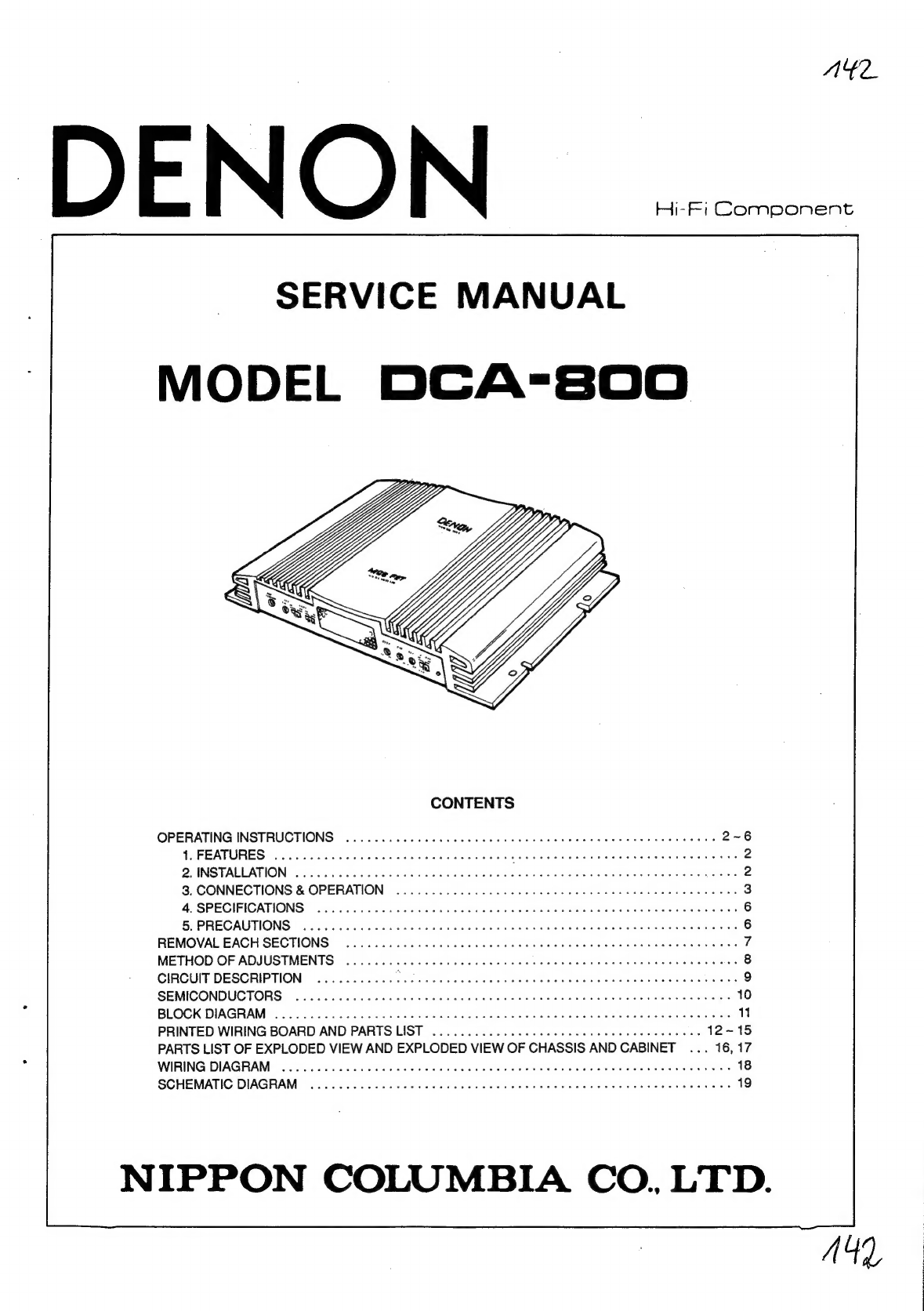
SERVICE
MANUAL
|
MODEL
DCA-800
CONTENTS
OPERATING
INSTRUCTIONS
1.
FEATURES
2.
INSTALLATION
3.
CONNECTIONS
&
OPERATION
4.
SPECIFICATIONS
5.
PRECAUTIONS
REMOVAL
EACH
SECTIONS
METHOD
OF
ADJUSTMENTS
CIRCUIT
DESCRIPTION
SEMICONDUCTORS
BLOCK
DIAGRAM
PRINTED
WIRING
BOARD
AND
PARTS
LIST
PARTS
LIST
OF
EXPLODED
VIEW
AND
EXPLODED
VIEW
OF
CHASSIS
AND
CABINET
-
WIRING
DIAGRAM
SCHEMATIC
DIAGRAM
NIPPON
COLUMBIA
CO.
LTD.
Please
read
carefully
all
safety
and
operating
instructions
before
installation
and
use.
It
will
help
you
to
obtain
the
best
performances
from
your
new
power
amplifier.
FEATURES
1.
Changeable
Multi-Channel
Power
Amplifier
with
Built-in
Subwoofer
Drive.
Maximum
Power
Output.
6
Channel
50W
x
6
(1
kHz/4
ohms,
1%
T.H.D.)
45W
x
6
(20
Hz~20
kHz/4
ohms,
0.1%
T.H.D.)
3
Channel
100W
x
3
(1
kHz/4
ohms,
1%
T.H.D.)
2.
High-power
Amplifier
with
MOS-FET.
With
their
high
speed
and
favorable
characteristics,
MOS-
FET
devices
are
idea!
for
the
powerstage
of
high-quality
amplifiers.
3.
Variable
Input
Sensitivity.
4.
Subwoofer
Amplifier
with
Crossover
Network.
5.
Adjustable
Subwoofer
Level.
0
~
+16
dB
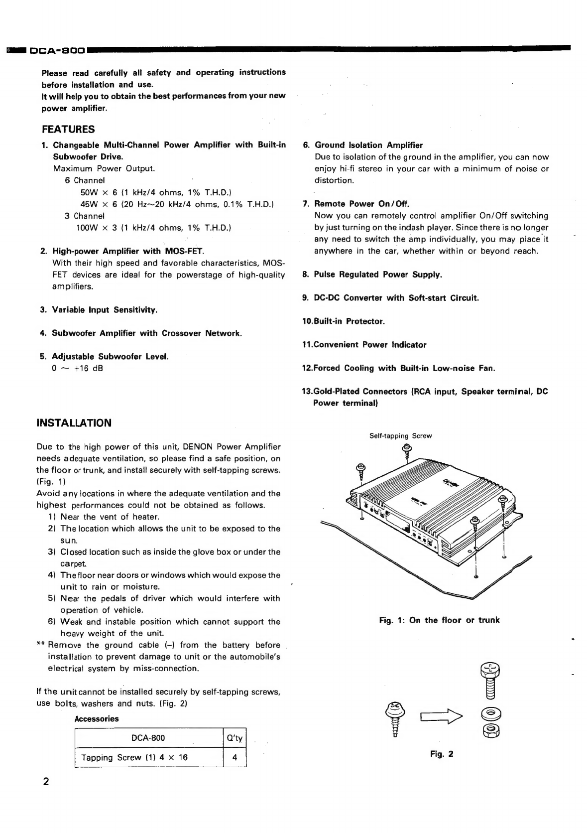
INSTALLATION
Due
to
the
high
power
of
this
unit,
DENON
Power
Amplifier
needs
adequate
ventilation,
so
please
find
a
safe
position,
on
the
floor
or
trunk,
and
install
securely
with
self-tapping
screws.
(Fig.
1)
Avoid
any
locations
in
where
the
adequate
ventilation
and
the
highest
performances
could
not
be
obtained
as
follows.
1)
Near
the
vent
of
heater.
2)
The
location
which
allows
the
unit
to
be
exposed
to
the
sun.
3)
Closed
location
such
as
inside
the
glove
box
or
under
the
carpet.
4)
The
floor
near
doors
or
windows
which
would
expose
the
unit
to
rain
or
moisture.
5)
Near
the
pedals
of
driver
which
would
interfere
with
operation
of
vehicle.
6)
Weak
and
instable
position
which
cannot
support
the
heavy
weight
of
the
unit.
**
Remove
the
ground
cable
(-)
from
the
battery
before
installation
to
prevent
damage
to
unit
or
the
automobile’s
electrical
system
by
miss-connection.
If
the
unit
cannot
be
installed
securely
by
self-tapping
screws,
use
bolts,
washers
and
nuts.
(Fig.
2)
Accessories
DCA-800
Q'ty
Tapping
Screw
(1)
4
x
16
Fees
Bam]
os
Neat
|
mw
2
a
a
NF
a
A
a
ea
a
6.
Ground
Isolation
Amplifier
Due
to
isolation
of
the
ground
in
the
amplifier,
you
can
now
enjoy
hi-fi
stereo
in
your
car
with
a
minimum
of
noise
or
distortion.
7.
Remote
Power
On/Off.
Now
you
can
remotely
control
amplifier
On/Off
switching
by
just
turning
on
the
indash
player.
Since
there
is
no
longer
any
need
to
switch
the
amp
individually,
you
may
place
it
anywhere
in
the
car,
whether
within
or
beyond
reach.
8.
Pulse
Regulated
Power
Supply.
9.
DC-DC
Converter
with
Soft-start
Circuit.
10.Built-in
Protector.
11.Convenient
Power
Indicator
12.Forced
Cooling
with
Built-in
Low-noise
Fan.
13.Gold-Plated
Connectors
(RCA
input,
Speaker
terminal,
DC
Power
terminal)
Self-tapping
Screw
Fig.
1:
On
the
floor
or
trunk
CONNECTIONS
&
OPERATION
After
the
DENON
Power
Amplifier
DCA-800
is
securely
instal-
led,
make
the
connections
as
follows.
1)
Connect
the
pre-out
from
your
component
to
the
input
of
DCA-800
Connect
the
speaker
wires
to
the
speaker
terminals
of
DCA-800.
*
Make
sure
the
polarity
of
left
and
right
speaker
line
is
observed.
*
Never
connect
the
speaker
wirers
of
each
speaker
together.
*
Never
make
the
plus
and
minus
wire
short-circuit.
*
Never
connect
the
speaker
wirers
to
the
car
chassis.
Secure
the
ground
wire
to
a
clean
bare
metal
spot
on
the
car
chassis.
Make
sure
paint
or
coating
is
scraped
away
for
best
connection.
(The
wire
gauge
should
be
10~12
AWG.)
Connect
the
remote
cord
to
the
remote
control
terminal
of
your
indash
player.
‘
(The
wire
gauge
should
be
18
AWG.)
Connect
the
battery
cord
directly
to
the
positive
(+)
terminal
of
battery.
(The
wire
gauge
should
be
10~12AWG.)
2
—
3
=
4
5
*
Make
all
connections
securely
to
prevent
noise.
Bind
up
the
cords
by
tape
after
connection.
*
Confirm
again
that
your
connection
follows
this
instruction
manual,
re-install
the
parts
of
your
automobile
as
they
were
and
re-connect
the
negative
(-)
cable
to
the
negative
(-)
terminal
of
the
battery.
*
if
your
indash
player
does
not
have
a
remote
terminal,
consult
your
DENON
Dealer
for
alternate
hook
up.
SUBWOOFER
LEVEL
CROSSOVER
ON/OFF
CROSSOVER
INPUT
SENSITIVITY
POWER
INDICATOR
SUBWOOFER
FRONT/REAR
MiD/HIGH
SUB
WOOFER
INPUT
SELECTOR
DC
POWER
TERMINAL
BLOCK
SPEAKER
TERMINALS
INPUT
JACK
To
REMOTE
To
GROUND
Tapping
Screw
_
Car
Chassis
(Metal)
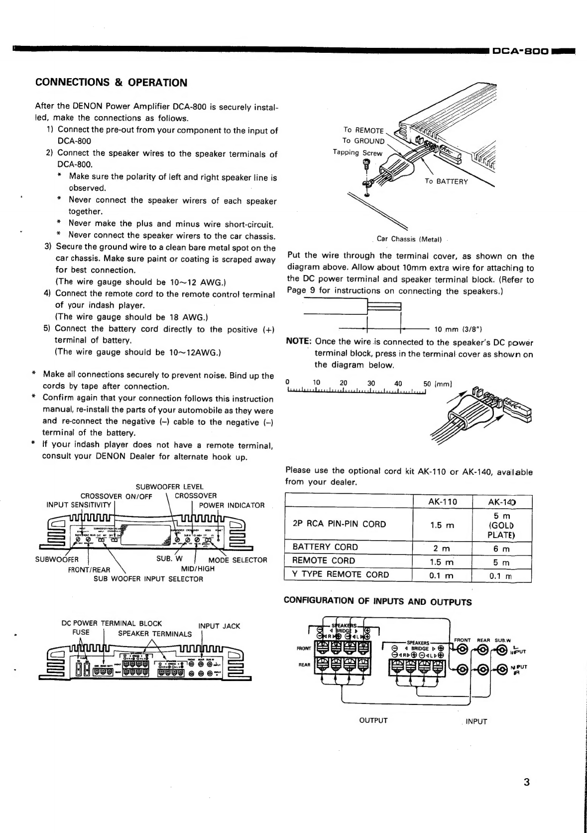
Put
the
wire
through
the
terminal
cover,
as
shown
on
the
diagram
above.
Allow
about
10mm
extra
wire
for
attaching
to
the
DC
power
terminal
and
speaker
terminal
block.
(Refer
to
Page
9
for
instructions
on
connecting
the
speakers.)
oe
a
10
mm
(3/8”)
NOTE:
Once
the
wire
is
connected
to
the
speaker's
DC
power
'
terminal
block,
press
in
the
terminal
cover
as
shown
on
the
diagram
below.
0
10
20
30
40
Please
use
the
optional
cord
kit
AK-110
or
AK-140,
available
from
your
dealer.
2P
RCA
PIN-PIN
CORD
BATTERY
CORD
REMOTE
CORD
Y
TYPE
REMOTE
CORD
(+)
FRONT
REAR
SUB.W
ui
SPEAKERS
rront
[ES
BS
ES
BS
[
«
BrinGe
p
@
N
Put
ww
so
ano@
Oaiv®
x
KUN
MN
LUN
POY
KUN
PUN
LN
Pn
rean
|G
eae
EEA)
NPUT
AS
|e
Se
|=
Fr
OUTPUT
INPUT
DCA-8SOO
mag

DcA-s00
1.
Stereo
mode
DCA-800
INPUT
SACK
e
Connect
the
pre-out
jacks
on
your
component
to
the
left
and
right
input
jacks
on
the
DCA-800.
Also,
connect
the
left
and
right
speaker
wires,
following
the
above
notes.
e
Set
the
mode
selector
to
the
2
ohms
or
4
ohms
position,
depending
on
the
impedance
of
the
speakers.
NOTE:
If
the
mode
selector
is
set
to
the
4
ohms
position
and
a
2
ohms
load
is
used
(2
ohms
speakers
or
4
ohms
speakers
connected
in
parallel),
the
sound
may
be
cut
off
when
playing
for
long
periods
of
time
at
high
temperatures
or
with
a
high
output.
This
is
not
a
malfunction
—
the
amplifier’s
high
temperature
protection
circuit
has
been
activated.
If
this
happens,
either
turn
the
volume
down
or
switch
the
mode
selector
to
the
2
ohms
position.
INPUT
SENSITIVITY
The
diagram
below
illustrates
which
inputs
the
INPUT
SENITIV-
ITY
act
upon.
tNPUT
SENSITIVITY
FRONT
REAR
SUB.W
SUB.W
FRONT/REAR
Pye
MIN
MAX
MIN
MAX
ae
The
sensitivity
increases
as
the
control
is
turned
clockwise.
SUBWOOFER
INPUT
SELECTOR
This
selector
switches
between
the
EXT
and
INT
signals
which
are
input
to
the
subwoofer
channel.
e
When
EXT
is
Selected
When
the
selector
has
been
set
to
EXT,
the
signal
connected
to
the
DCA-800
subwoofer
input
terminals
is
input
as
the
subwoofer
signal.
FRONT
REAR
SUB.W
2.
Mono
mode
DCA-800
INPUT
JACK
FRONT
Head
<—O-D
Unit
<-@
~
e
Set
the
mode
selector
to
the
2
ohms
position.
e
Use
speakers
with
an
impedance
of
4
ohms
or
greater.
NOTE:
The
above
procedure
for
using
the
stereo
mode
and
mono
mode
applies
to
both
the
front
and
rear
sub-
woofers.
If
using
the
mono
mode
on
even
one
of
the
six
channels,
set
the
mode
selector
to
the
2-ohm
position
(bridge).
e
When
INT
is
Selected
When
the
selector
has
been
set
to
INT,
the
left
channel
signal,
which
is
input
to
the
front
and
rear
channels
of
the
DCA-800,
is
input
to
the
left
channel
of
the
sub
woofer.
Similarly,
the
right
channel
signal,
which
is
input
to
the
front
and
rear
channels
‘of
the
DCA-800,
is
input
to
the
right
channel
of
the
subwoofer.
REAR
SUB.W
DCA-800
As
shown
on
the
diagram
above,
the
internal
subyoofer
filter
(low-pass
filter)
acts
on
the
subwoofer
signé,
The
cut-off
for
this
filter
is
adjusted
with
the
variable
ris
istor
shown
on
the
following
diagram.
CROSSOVER
SUB.W
MID/HIGH
@\
©)
4
20 40
=
120
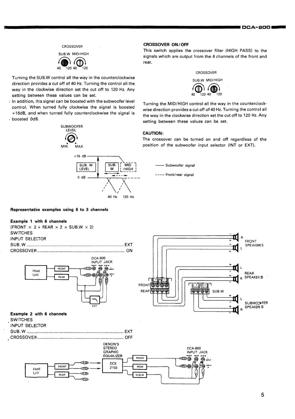
Turning
the
SUB.W
control
all
the
way
in
the
counterclockwise
direction
provides
a
cut
off
of
40
Hz.
Turning
the
control
all
the
way
in
the
clockwise
direction
set
the
cut
off
to
120
Hz.
Any
setting
between
these
values
can
be
set.
In
addition,
this
signal
can
be
boosted
with
the
subwoofer
level
control.
When
turned
fully
clockwise
the
signal
is
boosted
+16dB,
and
when
turned
fully
counterclockwise
the
signal
is
-
boosted
OdB.
SUBWOOFER
LEVEL
40 Hz
120
Hz
Representative
examples
using
6
to
3
channels
Example
1
with
6
channels
(FRONT
X
2+
REAR
x
2
+
SUB.W
x
2)
SWITCHES
INPUT
SELECTOR
DCA-800
INPUT
JACK
FRONT
REAR
SUBW
Example
2
with
6
channels
_
SWITCHES
INPUT
SELECTOR
SUB
WA2
colo
antes
inpninmichieutia
Sinieamatnunal
nea
EXT
EROSSOVER
hfe
cielarninail
aameneactercthariaralenetinnc
OFF
DENON’S
STEREO
GRAPHIC
EQUALIZER
CROSSOVER
ON/OFF
This
switch
applies
the
crossover
filter
(HIGH
PASS)
to
the
signals
which
are
output
from
the
4
channels
of
the
front
and
rear.
CROSSOVER
SUB.W
MID/HIGH
40
Turning
the
MID/HIGH
control
all
the
way
in
the
counterclock-
wise
direction
provides
a
cut
off
of
40
Hz.
Turning
the
control
all
the
way
in
the
clockwise
direction
set
the
cut
off
to
120
Hz.
Any
setting
between
these
values
can
be
set.
CAUTION:
The
crossover
can
be
turned
on
and
off
regardless
of
the
position
of
the
subwoofer
input
selector
(INT
or
EXT).
Subwoofer
signal
----
Front/rear
signal
R
FRONT
__
SPEAKERS
L
REAR
Rg
SPEAKERS
FRONT
Ber
Oere
L
SUBWOOFER
a
SPEAKER
S
DCA-800
INPUT
JACK
FRONT
AEAR
SUBW
DCA-s800
gf
DOCA-800
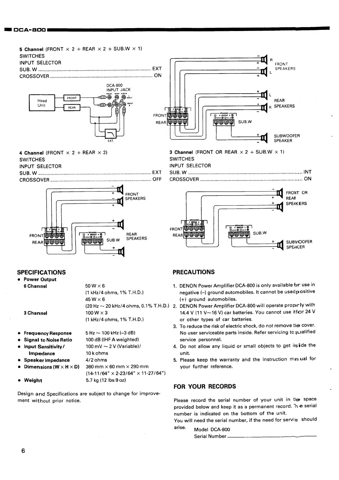
5
Channel
(FRONT
x
2
+
REAR
x
2
+
SUB.W
x
1)
SWITCHES
INPUT
SELECTOR
R
FRONT
7
SPEAKERS
DCA-800
INPUT
JACK
FRONT
REAR
SUEW
+
(|
R
SPEAKERS
<ar@
Oar0®
REAR
SUB.W
a
SUBWOOFER
EXT.
a
SPEAKER
4
Channel
(FRONT
x
2
+
REAR
x
2)
3
Channel
(FRONT
OR
REAR
x
2
+
SUB.W
x
1)
SWITCHES
SWITCHES
INPUT
SELECTOR
INPUT
SELECTOR
FRONT
Ty
FRONT
OR
SPEAKERS
REAR
SPEAKERS
REAR
suB.w
SPEAKERS
SUBVOOFER
+
SPEAKER
SPECIFICATIONS
PRECAUTIONS
e@
Power
Output
6
Channel
50W
x6
1.
DENON
Power
Amplifier
DCA-800
is
only
available
for
use
in
(1
kHz/4
ohms,
1%
T.H.D.)
negative
(-)
ground
automobiles.
It
cannot
be
usedpositive
45W
x6
(+)
ground
automobiles.
(20
Hz
~
20
kHz/4
ohms,
0.1%
T.H.D.)
2.
DENON
Power
Amplifier
DCA-800
will
operate
properly
with
3
Channel
100
W
x
3
14.4
V
(11
V~16
V)
car
batteries.
You
cannot
use
itfor
24
V
(1
kHz/4
ohms,
1%
T.H.D.)
or
other
types
of
car
batteries.
3.
To
reduce
the
risk
of
electric
shock,
do
not
remove
tle
cover.
e
Frequency
Response
5
Hz
~
100
kHz
(~3
dB)
No
user
serviceable
parts
inside.
Refer
servicing
to
qualified
e
Signal
to
Noise
Ratio
100
dB
(IHF
A
weighted)
service
personnel.
©
Input
Sensitivity
/
100
mV
~
2
V
(Variable)/
4.
Do
not
allow
any
liquid
or
small
objects
to
get
itside
the
impedance
10
kohms
unit.
e
Speaker
Impedance
4/2
ohms
5.
Please
keep
the
warranty
and
the
instruction
manual
for
e
Dimensions
(WxHxD)
360mm
x
60mm
x
290mm
your
further
reference.
(14-11/64"
x
2-23/64"
x
11-27/64")
:
e
Weight
5.7
kg
(12
lbs
9
oz)
FOR
YOUR
RECORDS
Design
and
Specifications
are
subject
to
change
for
improve-
ment
without
prior
notice.
Please
record
the
serial
number
of
your
unit
in
the
space
provided
below
and
keep
it
as
a
permanent
record.
he
serial
number
is
indicated
on
the
bottom
of
the
unit.
You
will
need
the
serial
number,
if
the
need
for
servite
should
arise.
Wiodel
DCA-800
Serial
Number

(Eo
oan
a
ST
a
(>
A-8O0
Baas
REMOVAL
OF
EACH
SECTION
(1)
Remove
4
tapping
screws
@
out
of
Bottom
Cover,
and
remove
Bottom
Cover
as
arrow
shows.
(2)
Remove
4
bind
screws
@,
and
remove
Front
Panel
as
arrow
shows.
(3)
Remove
8
bind
screws
@,
and
remove
4
bind
screws
@.
(4)
Remove
2
pan
screws
©,
and
remove
Fuse
Unit
Ass’y,
then
remove
Rear
Panel
as
arrow
shows.
_
(5)
Remove
2
bind
screws
@,
then
remove
Trans
Unit
Ass’y.
Front
Panel
(6)
Remove
3
bind
screws
@,
then
remove
Filter
Unit
Ass’y.
(7)
Remove
5
bind
screws
®
and
8
bind
screws
©,
then
remove
DC
Power
Unit
Ass’y.
(8)
Remove
4
bind
screws
@
and
7
bind
screws
@,
then
remove
Main
Unit
Ass’y.
(9)
Remove
2
bind
screws
(@®
,
then
remove
Fan
Ass’y.
Note:
Assemble
each
unit
in
reverse
oder
of
the
disassembly
procedure.
Main
Chassis
Assy

me
DOCA-so00
SIN
NT
TE
METHOD
OF
ADJUSTMENT
When
making
adjustments,
be
sure
the
power
supply
is
at
the
rated
voltage
and
the
room
air
is in
normal
condition
with
respect
to
temperature
and
humidity.
Secondary
Voltage
Adjustment
Adjust
VR801
so
that
the
voltage
across
the
both
ends
of
C802
reads
23.4
+
0.2
V
in
case
4
ohms
STEREO
MODE,
ACC
14.4
V,
No-signal
mode.
DIGITAL
O10}
voirmeter
VR6O6C
VR6OGE
Idling
Current
Adjustment
Under
the
state
of
power
voltage
14.4
V
and
no
load,
connect
DIGITAL
VOLTMETER
to
R630A,
630B,
630C,
630D,
630E,
630F
0.152
x
2)
as
per
the
above
Figure,
within
30
~
40
seconds
after
turning
power
on,
adjust
VR606A,
B,
C,
D,
E,
F
so
that
the
voltage
acness
the
both
ends
of
the
resistor
is
read
3
mV
~
15
mV
(10
mA~
50
mA).

CIRCUIT
DESCRIPTION
1.
AUDIO
SECTION
@
FET
Input,
FET
Output
DCA-800
newly
employs
an
operation
amplifier
which
is
a
J-FET
input
type
accommodating
high-through
rate
digital
source
in
the
input
first
stage
of
IC601,
602,
603.
Also,
in
the
output
stage,
employs
a
durable,
highly
reliable
MOS
FET
which
permits
high-output
sound
reproduction
having
a
high-steepened,
high-graded
quality.
@
Sub-woofer
A
sub-woofer
signal
is
feasible
by
using
VR603
to
boost
within
the
range
of
0
~
+16
dB
to
make
balancing
with
the
other
channels
when
sub-woofer
input
selector
SW601
is
set
at
INT.
Also,
this
signal
is
processed
with
a
-18
dB/Oct
low-pass
filter
composed
of
IC606.
The
filter's
cut-off
frequency
is
continuously
variable
within
the
range
of
40
Hz
~
120
Hz
by
VR604.
(Fig.
1)
_
®
Crossover
Circuit
An
input
signal
applied
to
the
front
and
rear
channels
can
be
processed
with
a
-12
dB/Oct
high-pass
filter
which
is
composed
of
IC607,
608
by
using
SW602
at
need.
The
filter's
cut-off
frequency
is
continuously
variable
within
the
range
of
40Hz
~
120
Hz
by
VR605.
(Fig.
1)
+16
Gain
(dB)
Sub
Woofer
Signal
————
Front/Rear
Signal
Frequency
Also,
the
independence
of
SW601
and
SW602
permits
separate
controlling
of
functions
@
and
@.
®
Grounding
Isolation
As
a
problem
of
amplifier
to
be
used
for
car,
the
grounding
position
difference
between
the
amplifier
and
the
in-dash
player
to
be
connected
invites
engine
noise(en)
overlap
in
the
input
signal.
In-dash
Ployer
ay
Power
Amplifier
if
A(@s+€n)
«
Upon
this,
for
DCA-800,
the
primary
side
and
secondary
side
of
power
supply
ground
are
isolated
and
the
secondary
side
ground
i.e.
audio
ground
to
the
in-dash
player
is
connected
to
solve
this
problem.
(Fig.
2)
es
DCA-800
ANS
in-dash
Player
2.
POWER
SUPPLY
SECTION
@®
Switching
Regulator
Controlling
Circuit
IC801
(4PC494C)
is
an
IC
for
switching
regulator
for
control
of
DC-DC
converter
circuit.
The
pulse
switching
DC-DC
converter
circuit
is
output
from
No.
9
and
No.
10
terminals,
and
is
adopting
the
Fixed
Frequency
Pulse
Width
Modulation
Method.
When
REMOTE
turns
ON,
causing
TR818,
819
turn
ON
and
the
Pin
2)
is
supplied
to
the
power.
Upon
the
power
supplied,
the
standard
voltage
(5V)
which
is
built
in
IC801
emits
from
Pin
@
and
impressed
to
Pin
@
through
C808.
After
that,
the
voltage
at
Pin
@
gradually
reduces
voltage
to
ground
level
with
the
time
constant
of
C808,
R817,
however,
with
this
effects,
the
pulse
width
emitted
from
the
Pins
@,
©
of
1C801
gradually
expands.
Accordingly,
occurring
of
rush-current
caused
by
the
steep
rise
of
power
at
REMOTE
ON
will
be
prevented.
(Soft
start)
This
number
of
frequency
is
determined
by
C817
and
R839.
Voltage
fluctuation
on
the
secondary
side
of
DC-DC
converter
caused
by
changes
of
power
voltage
and
load
is
captured
as
a
current
change
of
photo-coupler
(IC802),
and
the
pulse
width
is
changed
by
feedback
of
current
change
to
No.
10
terminal
via
VR801,
thus
the
secondary
voltage
will
be
controlled.
®
Toroidal
Transformer
T801
of
this
unit
is
adopting
a
small,
highly
efficient
toroidal
transformer
and
therefore
the
stable
power
voltage
can
be
supplied
at
the
time
the
output
power
is
high.
3.
COOLING
FAN
Acooling
fan
is
newly
employed
to
this
unit.
This
fan
starts
running
when
the
heat
sink
temperature
becomes
approx.
70°C
to
lower
the
temperature
inside
of
the
unit,
thus
each
part
of
amplifier
can
perform
stable
functions.
4.
PROTECTOR
CIRCUIT
@®
Protection
of
Speaker
C614
(uPC1237)
searches
various
abnormalities
and
executes
protective
operations.
@
Overload
Censoring
When
shortcircuit
or
overload
of
speaker
terminals
occurs,
current
at
(R630A
(B,
C,
D,
E,
F)
increases
causing
voltage
rise
of
this
resistance,
and
TR6O6A
(B,
C,
D,
E,
F)
turns
ON.
After
this,
due
to
turning
ON
of
TR608,
voltage
at
No.
6
terminal
of
IC614
increases
by
approximately
24V,
and
relay
(RL601)
turns
OFF
and
separates
the
speaker
from
the
amplifier.
@
DC
Voltage
Sensoring
Speaker
terminal
voltage
is
normally
approximately
OV
(DC).
However,
when
DC
voltage
comes
out
due
to
some
accident,
the
speaker
is
separated
to
prevent
from
breakage
or
burning
damage.
if
DC
voltage
appears
on
the
speaker
terminal,
it
will
be
added
to
No.
2
terminal
of
IC614,
and
the
voltage
at
No.
6
terminal
is
raised
up
to
approximately
24V,
thus
the
relay
(RL601,
602,
603)
turns
OFF.
e@
Acc
OFF
Sensoring
Acc
voltage
is
sensorate
via
R643,
ZD605
which.are
connected
to
No.
4
terminal
of
IC606,
and
the
relay
(RL601,
602,
603)
rapidly
turns
OFF
as
soon
as
Acc
becomes
OFF.
@
Thermal
Protection
When
temperature
inside
the
unit
rises,
resistance
of
thermistor
(TH802)
is
weakened
and
TR802
becomes
ON,
then
1C801
stops.
In
case
of
abnormal
high
temperature,
resonance
of
IC801
stops
and
then
DC-DC
converter
circuit
will
be
closed.
@®
Protection
Against
at
Excess
of
Primary
Voltage
If
a
16V
or
higher
voltage
applies
to
the
battery
terminal
should
happen,
the
voitage
is
impressed
to
TR817
via
ZD801,
R841
and
TR817,
816
make
conduct.
Then,
IC801
stops
the
output
to
protect
against
abnormal
rise
of
the
secondary
side
voltage
and
breakdown.
DCA-800
Bm”

DOCA-so0o0
10
SEMICONDUCTORS
e
IC’s
uPC1237H
(1C614)
8
uPC494C
(IC801)
NON
INV.
INV.
—
REF
OUTPUT
INPUT
INPUT
OUT
CONTROL
Vec
C2
REGULATOR
NON-
(NV.
FEED-DEAD-
CT
INV,
INPUT
BACK
TIME
INPUT
CONTRO
PC817
(IC802)
OVER
LOAD
DET
—2
E&I
im
R
NuM072
(IC601~603)
NJM2068SD
(IC604,606~613)
Vcc
ON
MUTE
a
3°
J
bre
a
a
re
CIRCUIT
RELAY
ORIVE
CIRCUIT
ATCH/AUTO
ETURN
SW
'
DEAD
TIME
COMPARATOR
Ot
>
OE
AD
~
TIME
CONTROL
NON-INV.
INPUT
WV.
INPUT
COMPARATOR
NON-
INV.
INPUT
INV.
INPUT
FEED
Back
(3)
MJM78M12
(IC616)
1
Anode
2
Cathode
3
Emitter
4
Collector
1:
Output
2:
Input
3:
GND
OUTPUT
CONTROL
NJM79M12
(C615)
e
TRANSISTORS
2SA1175
(E/F/K)
2SB1007
(Q/R)
2SC4495
28C1627A(O/Y)
2SC2785
(E/F/K)
B
(Base)
i
B
(Base)
C
(Collector)
E
(Emitter)
Mots
(Emitter)
C
(Collector}
E
(Emitter)
o™
¢
(Collector)
C
(Collector)
E
(Emitter)
eas
(Base)
SS
(Base)
2SA1559
2SD1065
(R/S)
2SA817A
(0/Y)
2SC4037
1
Emitter/GND
2
Collector/OUT
E
(Emitter)
3
3
Base/IN
C
(Collector)
B
(Base)
1?
B
(Base)
———
C
(Collector)
E
(Emitter)
2SJ174
DTA114ES
2SK1296
2SJ174
2SK1296
2
2
i
RI
our
R2
1
1
GID
(4)
TEmitter/GND
—-R1,-R2:10k2
2
Collector/OUT
tN
Our
lescurey
23
3
Base/IN
2:
Gate
3
3
;
GND
(+)
3:
Drain
e
DIODES
(including
LED)
6A2
MTZ16B
188136
CTG33S
CTG33R
MTZ6.8B
MTZ8.2B
MTZ27B
MTZ6.2B
=)
eq
MTZ12B
Puple
Silver
oe
t
3
oe
3
3
12°
2
12
2
RD12F,B1
(Posistor)
(LED)
PTH487-471BD
GL-5PR8
(2)
tow
y'
Yel
=
}
Blue
Cathode
Anode
We
ncaa

DCA-s800m
;
5
5S
?
;
Pa
ag
BLOCK
DIAGRAM
9
DRIVER
=
ERE
OREN
aE
eee
TREOSA,
6048
Faas
TR
ae
POO
:
:
40H
gap
/oct
!
;
i
ro-8
20
Hz
I
|
‘BASS
LEVEL
LPF
t ;
=
CONTROL
Ic606
(1/2)
|
sweol
&°-2
1604
(1/2)
H
RL6O3
Rech
—eo-O©
f
,
a
;
x
VR603
t
0
Reh
C
GAIN
INVERTOR
‘
Roth
16609(1/2)
BASS
LEVEL
4
“CONTROL
:
eal
(€604(1/2)
:
sna
si
eterna
keno
alee
cain
z
40ND
soaByoct
4
120Hz
Leh
©
CONTROL
|
166030172)
HPF
|
DRIVER
Ieeo71/2)
F
|
AMP
x
a
ic6l2tv2)
vR602
eo
|
bie
ag
7
|
|
(re
12dB/0CT
4
GAIN
RO
CONTROL
_
o!
INVERTOR
1cs02(2/2)
3
1
Licelotiza)
|
|
vR602
VR605
|
i
oe
selena
ARR
RRR
RC
Am
REND
APE
SEN
HEM
EEN
ser:
omar
Reset
tN
sea
a
el
AV
RAPA
REP
el
RS
ES
A
PN
aC
seston
CORRES?
SSE
sansa,
opanaeeR
aR
RAS
arta
aaa
Ra
UNO
HE
A
ARR
RR
Se
ra
URE
oC
oBMCCRRCTR
:
sweo2
:
i
by
|
{e
12B/0CT
:
4
GAIN
20Hz
DRIVER
:
La@
CONTROL
=
TRGO3E,
604E
$$
0
—@
1C6031172)
HPF
{
605E,
6O7E
\
eon
‘S)
|
=
106081172)
t
'
a
5
|
MONO
ei
vR602
OVERLOAD
&
1
&°-
Ory
|
!
TREO6E
acca
©
RLGO!
Rei
OS
9
rf
a
40H
,
{
§
12dB/0CT
4
MO®
oe
:
=
ie
Pree
|
|
CONTROL
1C60212/2)
HPF
.
retatheay
:
1c607(1/2)_}
:
ee:
ret
seer
a
7
een
miei
ean
com
ovoetiermaa
emmotneaiaatremene
oe
een
:
VR602
:
VR605
;
:
;
4
801,803
j
:
:
RECT
T801,802
E
:
_
Dc-
0¢.
5
a+
@
CONVERTOR
eos
he
:
TRAOI
~
Bil2
1ce0!
is
F802
7
:
~
8+®
VOLTAGE
:
pene
1803
|
go;
sweot
TEMPERARE
PROTECTOR
A
CONVERTER
we
orn-0
©
BATT
*e08
OVERVOLTAGE
PROTECTOR
B+
a+
ow?
40
TH8O2
,
TR8IG,8i7,
ZD801
i
mmeenene
*
ect
-
7
20
(MONO)
Te
cspessapsaeates
~~
ee
Sit
ter
ssiectasa
NO
AB
C85
5
LE
RGR
GG
ERIE
LAY
II
AR
GND
re
LOL
ELL
IPL
LID
ELM
ETEE
EILEEN
LE
NOL
GEL
IIE
AP
RENE
S
EOE
LAB
SS
SEE!
itt
tre
scam
BRE
SESSLER
ENG
BS
UEP
EE
ESN
CR
RE
ee
i
:
B+
SWITCH
:
:
g
=|
TRAI8,
819
REGULATOR
,
E
ji
ies
é
‘cane
‘
osi0
¥
O
REMOTE
s
VRBO!
i
|
ae
&
H
11
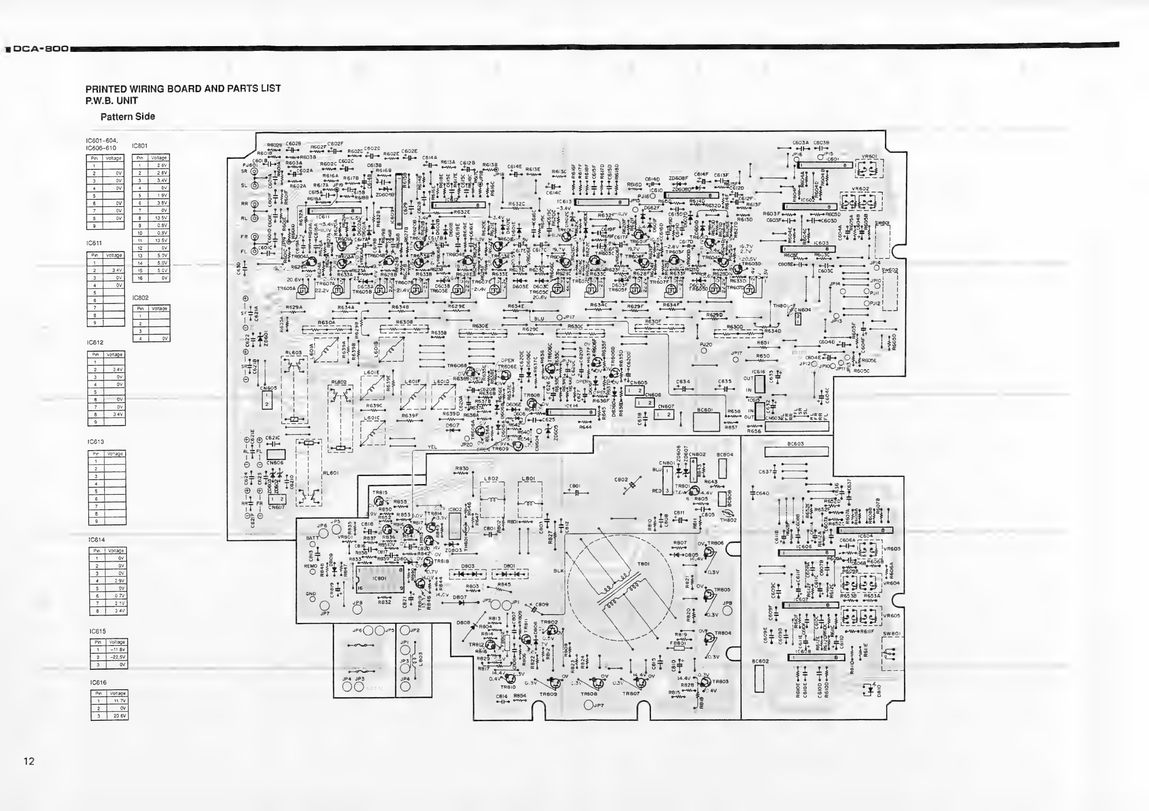
DCA-800
PRINTED
WIRING
BOARD
AND
PARTS
LIST
P.W.B.
UNIT
Pattern
Side
1C601~604,
IC606~610
1801
[Pin
|
Voltage
|
Voltage
pa
3
|
3av
Pst
|
j
6
|
ov]
7
ov
9
0.9V.
|
to
|
ov]
da
Sl
BO
Lec
Pin
|
Voltage
2
~22.5V
IC616
12
:
oN
cee
8
ry
eo
mo
a
:
:
©
92%
oe
te
A
been
38
-
cosets
|
3
cee
TReOeB
Sun
TREO
EE
eS
SPI2O
pio
O-%
iT
~
ove
8
at?
VOY
grr
>)
“-
RESEBOPENE
AO
é
}
° ‘
re
4
Tey
.
SROV
:
(S208
Bek
8
»Reo2e
Cf
Reois
c60lBy,
a
pusol
Thos
@
_
C6IGE
CEISF
zD608F
-
‘
Ste
oh
se
zbeospe
Pre
oweecsi2p
"
By
er
Rear.
po”
#
ReisF
owe
ekeceisp
eweRSIOF
We
RGITD
:
©
rc
16
aS
“
Ne
<-3.4V9
Re
QL
iv
OF
=
BBB.
GS
eee
Boo
_
YREOIA
Ce
TAS
420:5V
SL
TREOSD™
aye
O|
>
ERS
ie
4
_Jols)
Ressp
|S
oO
-
>
ae
tot
op
we
Be
|
TEASE
ot
5
sy
satis
BF
1S
J)
R637B
9
_
__]
©
+freszh”
9
R639D
pesga
*
#
D.
——s
S
¥
Oo;
a
eg
TER
DE0GDe-fq-o
R636De-Wre
R645
oy
N
eF9
aLeeL
te
©
©
none
Si
873
nor
ae
FR
|
Oz
©
=
a
ON
|
pis:
©
e
Vv
sr
one
N44
we].
ee
Ps
to
®
VR8O|
Re37
~RBSE
-
/
lo
co
cals
RESIOV.
OY
pt
EG
tee
ee
tH
cado
lav
o&
RB3S
C8i7T,
oN
re
{be
eWeRS4I2
oy
=
.
Ress
RE39"'ZD80.
5
VAD
TREI8
c
boos
-
ov’
D803
80!
2
Sig
rv
ee]
(odes)
o
:
N4OVes
cote
ete
.
R803
~
R845
:
ewe
©
1,
R632.
Mees
JP4
JP3
OO...
R6IOE
WW
c8l4
R854
ihe
ore
DCA-B800
===
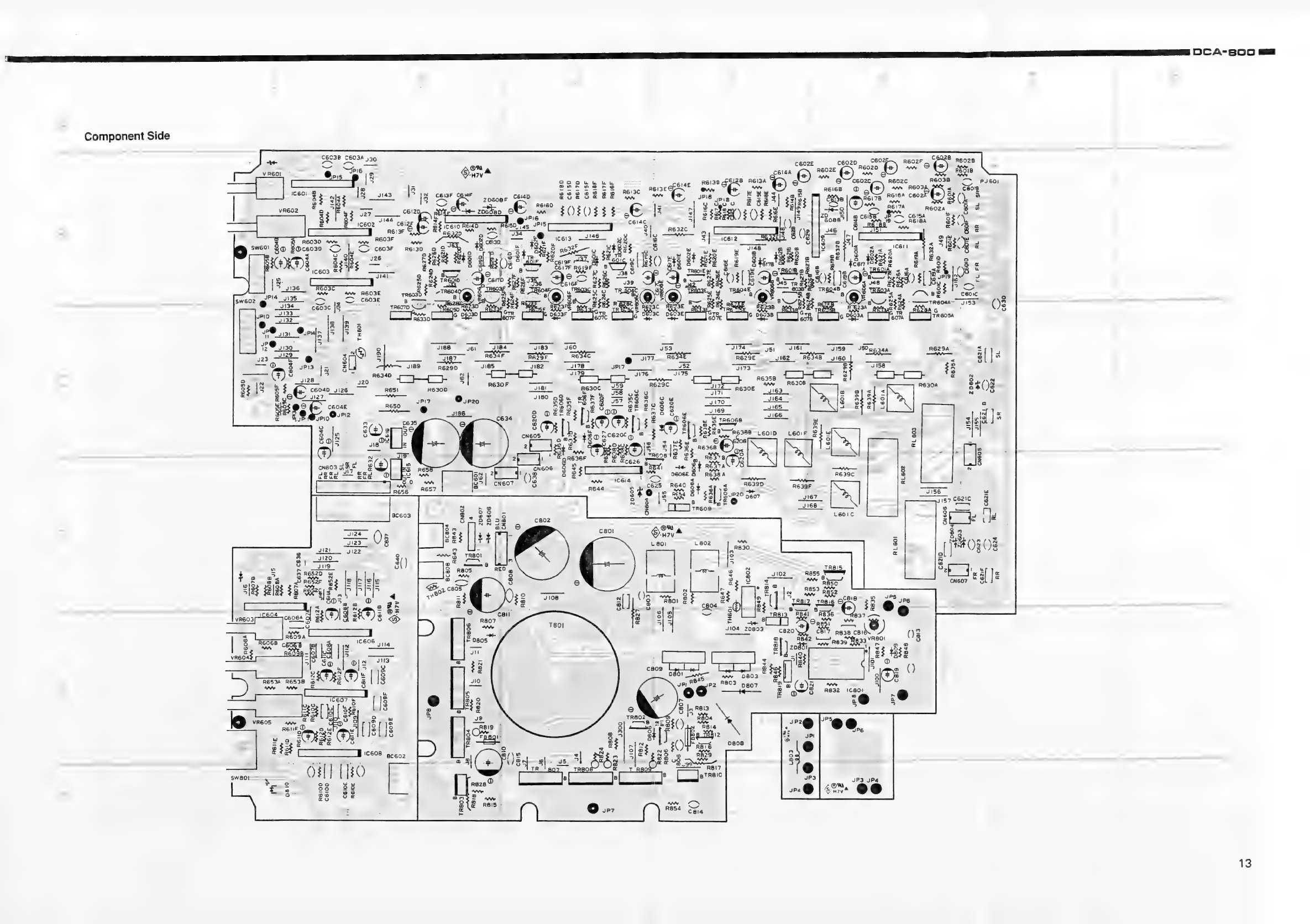
Component
Side
cae
Reise
GS
28
RG6IZA
22
be
2.2
:
ae
ayy
ae,
iceo2
~'**
cei:
ee
52
e
ae
A
R832
1C80l_
JP3
JP4
13
ag
DCA-s00
NE
OO
ig
Apne
eg
Ee
eg
ne
|
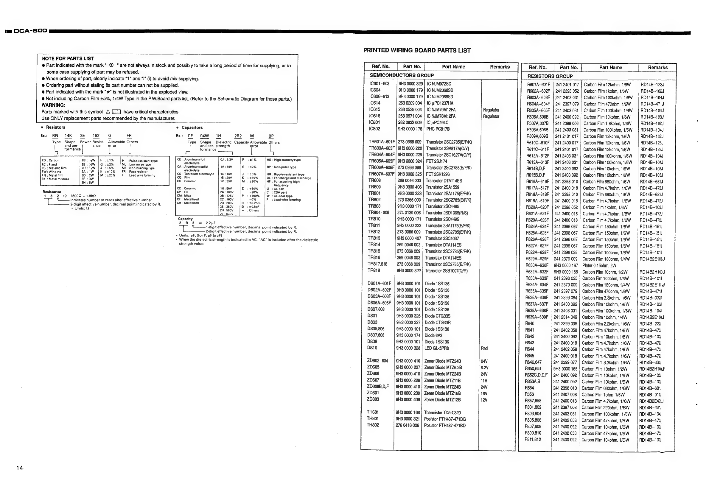
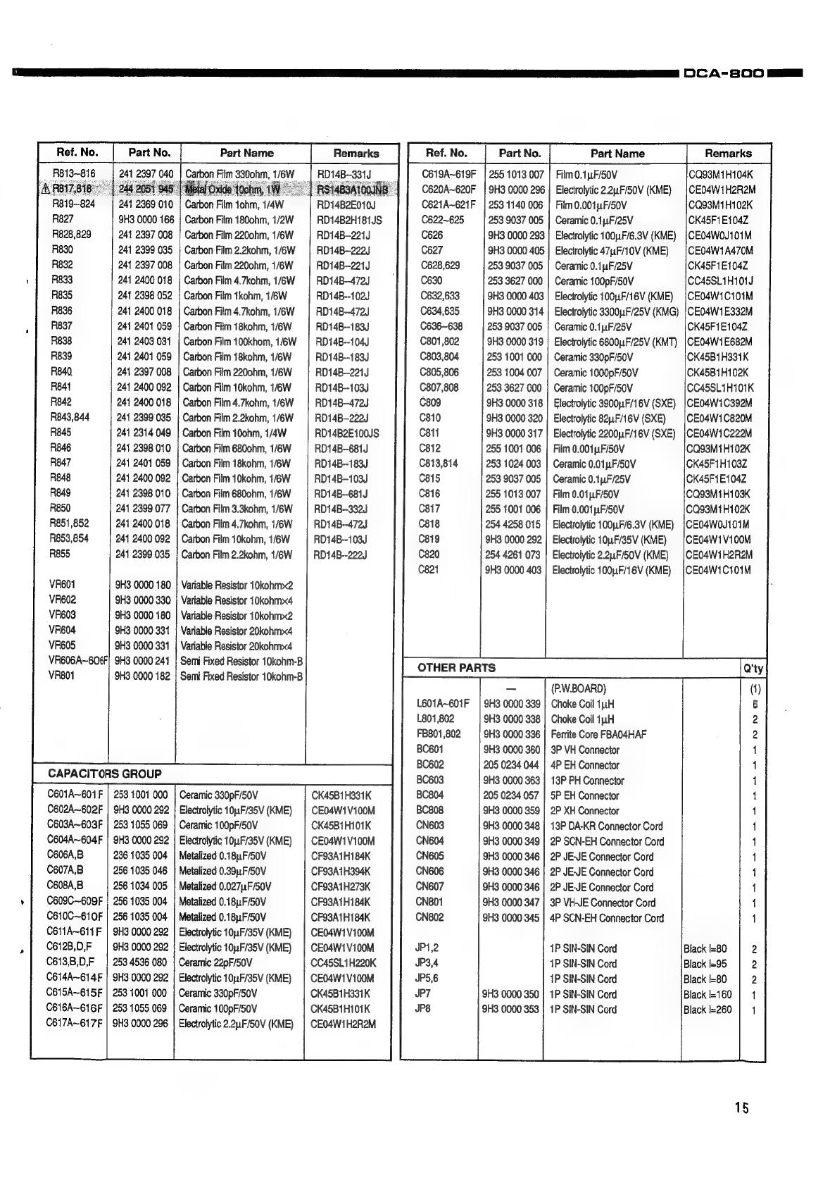
PRINTED
WIRING
BOARD
PARTS
LIST
NOTE
FOR
PARTS
LIST
@
Part
indicated
with
the
mark"
©
"are
not
always
in
stock
and
possibly
to
take
a
long
period
of
time
for
supplying,
or
in
some
case
supplying
of
part
may
be
refused.
@
When
ordering
of
part,
clearly
indicate
"1"
and
"I"
(i)
to
avoid
mis-supplying.
@
Ordering
part
without
stating
its
part
number
can
not
be
supplied.
Ref.
No.
Part
No.
Part
Name
Remarks
RESISTORS
GROUP
R601A~601F
|
2414
2401
017
|
Carbon
Film
12kohm,
1/6W
RD14B--123J
Ref.
No.
Part
No.
|-
Part
Name
Remarks
SEMICONDUCTORS
GROUP
1C601~603
|
9H3
0000
329
|
IC
NJMO72SD
@
Part
indicated
with
the
mark
"x"
is
not
illustrated
in
the
exploded
view.
een
zi
pee
i:
a
ene
iseeesed
-
ae
Be
ae
sd
puke
beets
o
i
i i
%,
1/4W
Type
in
the
P.W.Board
parts
list.
(Refer
to
the
Schematic
Diagram
for
those
parts.
‘<
!
;
a
:
oe
PaIpan
Fim
ae
pene
Snipa
eh
erat
leat
oe
pete)
Ic614
263
0209
004
|
IC
uPC1237HA
R604A~G04F
|
241
2397
079
|
Carbon
Film
4700hm,
1/6W
|
RD14B-~-471J
Parts
marked
with
this
symbol
\
[EZ]
have
critical
characteristics
10615
263
0539
004
|
IC
NJM79M12FA
Regulator
R605A~605F
|
241
2403031
|
Carbon
Film
100kohm,
1/6W
|
RD14B--104J
Use
ONLY
|
ee
oe
Hie
(des
miriendied
by
the
macuraanirer
:
IC616
263
0571
004
|
IC
NJM78M12FA
Regulator
R606A,606B
|
241
2400
092
|
Carbon
Film
10kohm,
1/6W
RD14B--103J
ute
EDS
ee
:
:
C801
262
0832
009
|
IC
pPC494C
R607A,607B
|
241
2399.06
|
Carbon
Film
1.6kohm,
1/6W
|
RD14B—t62U
e
Resistors
e
Capacitors
IC802
9H3
0000
178
|
PHC
PC817B
R608A,608B
|
241
2403
031
|
Carbon
Film
100kohm,
1/6W
RD14B-104J
Ex.:
RN
14K
2E
182
G
FR
Ex:
CE
O4W
1H
2R2
MM
BP
R609A,609B
|
241
2401
017
|
Carbon
Film
12kohm,
1/6W
RD14B--123J
Type
Shape
Power
Resist-
Allowable
Others
Type
Shape
Dielectric
Capacity
Allowable
Others
TR601A~601F
|
273
0366
009
|
Transistor
2SC2785(E/F/K)
R610C~610F
|
241
2400
017
|
Carbon
Film
12kohm,
1/6W
RD14B-:123J
L
Ae
abe
|
Ble
Error
pa
bee
a
reuaen
error
TR603A~603F
|
9H3
0000
222
|
Transistor
25A817A(O/Y)
RG611C~611F
|
241
2401
017
}
Carbon
Film
12kohm,
1/6W
|
RD14B--123
1
TR604A~604F
|
9H3
0000
225
|
Transistor
2SC1627A(O/Y)
R612A~612F
|
241
2403
031
|
Carbon
Film
100kohm,
1/6W
RD14B--104J
:
Carbon
:
‘0
:
:
Pulse-resistant
type
Se
foil
:
:
High
Stability
type
TR605A~605F
|
9H3
0000
324
|
FET
28/174
R613A~613F
|
241
2403
031
|
Carbon
Film
100kohm,
1/6W
RD14B~104J
serait
a
Reha
oitabicinte
:
Aluminum
solid
it
Non-polar
type
TR606A~606F
|
273
0366
099
|
Transistor
2502785(E/F/K)
R614B,D,F
|
241
2400
092
|
Carbon
Film
10kohm,
1/6W
|
RD14B--103J
Winging
:
:
:
Fuse
resistor:
‘Tantalum
electrolyte
:
15%
:
Ripple-resistant
type
TR607A~607F
|
9H3
0000
325
|
FET
2SK1296
R6158,D,F
241
2400
092
|
Carbon
Film
10kohm,
1/6W
RD14B--103J
Metal
film
‘ :
ziLead
wire-torming
:
Film
:
110%
:
For
charge
and
discharge
:
Metal
mixture
cate
Ene
ee
eerao
eames
siy
TR608
269
0046
003
|
Transistor
DTA114ES
R616A~616F
|
241
2398
010
|
Carbon
Film
680chm,
1/eW
‘|
RD14B--681J
cee
'
nee
taney
TR609
9H3
0900
406
|
Transistor
2541559
R617A~617F
|
241
2400
018
|
Carbon
Film
4.7kohm,
1/6W
|
RD14B--472J
Resistance
:Oil
:
-20%
:
CSA
part
TR801
9H3
0000
223
|
Transistor
2SA1175(E/F/K)
R618A~618F
|
244
2398
010
|
Carbon
Film
6800hm,
1/6W
RD14B--681
1
8
2
1800
=
1.8kQ
:
Mica
—
: >
+100%
:UL-CSA
type
_
Ra
2
’
|
L——-
Indicates
number
of
zeros
after
effective
number
:
bapa
:
:
i
A
:
Lead
wire
forming
TR802
273
0366
009
|
Transistor
25C2785(E/F/K)
R619A~619F
|
241
2400
018
|
Carbon
Film
4.7kohm,
1/6W
RD14B-472)
Se
ee
ee
eee
:
20.5pF
TR803
9H3
0000
171
|
Transistor
25C4495
R620A~620F
|
241
2398
052
|
Carbon
Film
tkohm,
1/6W
|
RD14B--102J
:
:
Others
TR804~809
|
274
0139006
|
Transistor
25D1065(R/S)
RE2IA~621F
|
241
2400
018
|
Carbon
Film
4.7kohm,
1/6W
|
RD14B-472J
Capacity
TR810
9H3
0000
171
|
Transistor
2504495
R623A~623F
|
241
2400
018
|
Carbon
Film
4.7kohm,
1/6W
RD14B--472)
2
R
2
>
22uF
:
Trig
effective
number,
decimal
point
indicated
by
R.
TR811
9H3
0000
223
|
Transistor
25A1175(E/F/K)
R624A~624F
|
241
2396
067
|
Carbon
Film
150ohm,
1/6W
RD14B--151J
2-digit
effective
number,
decimal
point
indicated
by
R.
TR812
273
0366
009
|
Transistor
25C2785(E/F/K)
R625A~625F
|
241
2396
067
|
Carbon
Film
1500hm,
1/6W
RD14B--151
s
Wligt
the
ele
ne
etrorh
ielficiesiedl
inNt,
RC
te
inelaaodaitot
tig
allot
TR813
SH3
0000
407
|
Transistor
28C4037
R626A~626F
|
241
2396
067
|
Carbon
Film
1500hm,
1/6W
|
RDt4B--181)
strength
value.
TR814
269
0046
003
|
Transistor
DTA114ES
R627A~627F
|
241
2396
067
|
Carbon
Film
150ohm,
1/6W
RD14B--154J
TR815
273
0366
009
|
Transistor
2SC2785(E/F/K)
R628A~628F
|
241
2396
025
|
Carbon
Film
1000hm,
1/6W
RD14B-101)
R629A~629F
|
241
2370
009
|
Carbon
Film
1800hm,
1/4W
RD14B2E18
J
R630A~630F
|
9H3
0000
167
|
Plater
0.15chm,
2W
R632A~632F
|
9H3
0000
165
|
Carbon
Film
10ohm,
1/2W
RD14B2H1t0J
R633A~633F
|
241
2396
025
|
Carbon
Fim
1000hm,
1/6W
RD14B--101)
R634A~634F
|
241
2370
009
|
Carbon
Film
1800hm,
1/4W
RD14B2E18
J
R635A~635F
|
241
2397
079
|
Carbon
Film4700hm,
1/6W
|
RD14B--471)
R636A~636F
|
241
2399
064
|
Carbon
Film
3.3kohm,
1/6W
|
RD14B--332)
R637A~637F
|
241
2400
092
|
Carbon
Film
10kohm,
1/6W
RD14B--103)
R638A~638F
|
241
2403
031
|
Carbon
Film
100kohm,
1/6W
|
RD14B--104)
R639A~639F
|
2414
2314
049
|
Carbon
Film
10ohm,
1/4W
RD14B2E10J
R640
241
2399
035
|
Carbon
Film
2.2kohm,
1/6W
—_|
RD14B--222)
R641
241
2402
058
|
Carbon
Film
47kohm,
1/6W
RD14B--473
R642
241
2400
092
|
Carbon
Film
10kohm,
1/6W
RD14B--103)
R643
244
2400
018
|
Carbon
Film
4.7kohm,
1/6W
|
RD14B--472
R644
241
2402
058
|
Carbon
Film
47kohm,
1/6W
RD14B--479)
R645
241
2400
018
|
Carbon
Film
4.7kohm,
1/6W
|
RD14B--472
R646,647
241
2399
077
|
Carbon
Film
3.3kohm,
1/6W
=;
RD14B--332
R650,651
9H3
0000
165
|
Carbon
Film
100hm,
1/2W
RD14B2H10J5
R652C,D,E,F
|
241
2400
092
|
Carbon
Film
10kohm,
1/6W
RD14B--103)
R653A,B
241
2400
092
|
Carbon
Film
10kohm,
1/6W
RDi4B--103)
R654
241
2398
010
|
Carbon
Film
6800hm,
1/6W
RD14B--681
R656
241
2407
008
|
Carbon
Film
1ohm
1/6W
RD14B8--010
R657,658
241
2400
018
|
Carbon
Film
4.7kohm,
1/6W
=|
RD14B2E42J
R801
,802
241
2397
008
|
Carbon
Film
2200hm,
1/6W
RD14B--221,
R803,804
241
2403
031
|
Carbon
Film
100kohm,
1/6W
=|
RD14B--104:
R805,806
241
2402
058
|
Carbon
Film
47kohm,
1/6W
RD14B--473,
R807,808
241
2400
092
|
Carbon
Film
10kohm,
1/6W
RD14B--103
R809,810
241
2402
058
|
Carbon
Film
47kohm,
1/6W
RD14B--473,
R811,812
244
2400
092
|
Carbon
Film
10kohm,
1/6W
RD14B--103
TR816
269
0046
003
|
Transistor
DTA114ES
TR817,818
273
0366
009
|
Transistor
26C2785(E/F/K)
TR819
9H3
0000
322
|
Transistor
2SB1007(Q/R)
D601A~601F
|
9H3
0000
101
|
Diode
1SS136
D602A~602F
|
9H3
0000
101
|
Diode
1SS136
D603A~603F
|
9H3
0000
101
|
Diode
1SS136
D606A~606F
|
9H3
0000
101
|
Diode
1SS136
D607,608
9H3
0000
101
|
Diode
1$S136
D801
9H3
0000
326
|
Diode
CTG33S
D803
9H3
0000
327
|
Diode
CTG33R
D805,806
9H3
0000
101
|
Diode
1S$136
D807,808
9H3
0000
174
|
Diode
6A2
D809
9H3
0000
101
|
Diode
1SS136
D810
9H3
0000
328
|
LED
GL-5PR8
ZD602~604
|
9H3.
0000
410
|
Zener
Diode
MTZ24B
ZD605
9H3
0000
227
|
Zener
Diode
MTZ6.2B
ZD606
9H3
0000
410
|
Zener
Diode
MTZ24B
ZD607
9H3
0000
229
|
Zener
Diode
MTZ11B
ZD608B,D,F
|
9H30000
410}
Zener
Diode
MTZ24B
ZD801
9H3
0000
230
|
Zener
Diode
MTZ16B
ZD803
9H3
0000
409
|
Zener
Diode
MTZ12B
TH601
9H3
0000
168
}
Thermister
TD5-C320
TH801
9H3
0000
321
|
Posistor
PTH487-471BG
TH802
276
0416
026
|
Posistor
PTH487-471BD
14
R827
R828,829
R830
R832
R833
R835
R836
R837
R838
R839
R840.
Re41
R842
R843,844
R845
R846
R847
R848
R849
R850
R851,852
R853,854
R855
VR601
VR602
VR603
VR604
VR605
VR606A~6O6F
VR801
C601A~601
F
C602A~602F
C603A~603F
C604A~604F
C606A,B
C607A,B
C608A,B
C609C~609F
C610C~610F
Cé11A~611
F
C612B,0,F
C613,B,D,F
C614A~614F
C615A~615F
C616A~616F
C617A~617F
9
0
9H3
0000
166
241
2397
008
241
2399
035
241
2397
008
241
2400
018
241
2398
052
241
2400
018
241
2401
059
241
2403
031
241
2401
059
241
2397
008
241
2400
092
241
2400
018
241
2399
035
241
2314
049
241
2398
010
241
2401
059
241
2400
092
241
2398
010
241
2399
077
241
2400
018
241
2400
092
241
2399
035
9H3
0000
180
9H3
0000
330
9H3
0000
180
9H3
0000
331
9H3
0000
331
9H3
0000
241
9H3
0000
182
253
1001
000
9H3
0000
292
253
1055
069
9H3
0000
292
236
1035
004
256
1035
046
256
1034
005
256
1035
004
256
1035
004
9H3
0000
292
9H3
0000
292
253
4536
080
9H3
0000
292
253
1001
000
253
1055
069
Carbon
ilm
10
rm,
1/4
9H3
0000
296
|
RefNo.
|
Part
No.
Part
Name
i/6W
if
Carbon
Film
1800hm,
1/2W
Carbon
Film
2200hm,
1/6W
Carbon
Film
2.2kohm,
1/6W
Carbon
Film
2200hm,
1/6W
Carbon
Film
4.7kohm,
1/6W
Carbon
Film
tkohm,
1/6W
Carbon
Film
4.7kohm,
1/6W
Carbon
Film
18kohm,
1/6W
Carbon
Film
100khom,
1/6W
Carbon
Film
18kohm,
1/6W
Carbon
Film
2200hm,
1/6W
Carbon
Film
10kohm,
1/6W
Carbon
Film
4.7kohm,
1/6W
Carbon
Film
2.2kohm,
1/6W
Carbon
Film
10ohm,
1/4W
Carbon
Film
680ohm,
1/6W
Carbon
Film
18kohm,
1/6W
Carbon
Film
10kohm,
1/6W
Carbon
Film
6800hm,
1/6W
Carbon
Film
3.3kohm,
1/6W
Carbon
Film
4.7kohm,
1/6W
Carbon
Film
10kohm,
1/6W
Carbon
Film
2.2kohm,
1/6W
Variable
Resistor
10kohmx2
Variable
Resistor
10kohmx4
Variable
Resistor
10kohm~2
Variable
Resistor
20kohmx4
Variable
Resistor
20kohmx4
Semi
Fixed
Resistor
10kohm-B
Semi
Fixed
Resistor
10kohm-B
CAPACITORS
GROUP
Ceramic
330pF/50V
Electrolytic
10F/35V
(KME)
Ceramic
100pF/50V
Electrolytic
10,.F/35V
(KME)
Metalized
0.18,F/50V
Metalized
0.39,.F/50V
Metalized
0.027F/S0V
Metalized
0.18,
F/50V
Metalized
0.18uF/50V
Electrolytic
10,4F/35V
(KME)
Electrolytic
10uF/35V
(KME)
Ceramic
22pF/50V
Electrolytic
10u.F/35V
(KME}
Ceramic
330pF/50V
Ceramic
100pF/50V
Electrolytic
2.2uF/50V
(KME)
‘|
RDI4B2E010)
RD14B2Hi81JS
RDi4B-221J
RD14B--222J
RD14B--221J
RD14B--472J
RD14B--102J
RD14B--472J
RD14B--183J
RD14B~-104J
RD14B--183J
RDi4B-221J
RD14B--103J
RD14B--472J
RD14B--222J
RD14B2E100JS
RD14B-681J
RD14B--183J
RD14B-103J
RD14B--681J
RD14B~-332J
RD14B--472J
RD14B--103J
RD14B--222J
CK45B1H331K
CEO4W1Vi00M
CK45B1H101K
CE04W1V100M
CF93A1H184K
CF93A1H394K
CF93A1H273K
CFOSATH184K
CF93A1H184K
CE04W1V100M
CE04W1V100M
CC45SL1H220K
CE04W1V100M
CK45B1H331K
CK45B1H101K
CEO4W1H2R2M
C619A~619F
C620A~620F
C621A~621F
C622~625
C626
C627
C628,629
C630
C632,633
C634,635
C636~638
C801
,802
C803,804
C805,806
C807,808
C809
C810
C811
C812
C813,814
C815
C816
C817
C818
C819
C820
C821
OTHER
PARTS
L601A~601F
L801
,802
FB801,802
BC601
BC602
BC603
BC804
BC808
CN603
CN604
CN605
CN606
CN607
CN801
CN802
JP1,2
JP3,4
JP5,6
JP7
JP8
255
1013
007
9H3
0000
296
253
1140
006
253
9037
005
9H3
0000
293
9H3
0000
405
253
9037
005
253
3627
000
9H3
0000
403
9H3
0000
314
253
9037
005
9H3
0000
319
253
1001
000
253
1004
007
253
3627
000
9H3
0000
318
9H3
0000
320
9H3
0000
317
255
1001
006
253
1024
003
253
9037
005
255
1013
007
255
1001
006
254
4258
015
9H3
0000
292
254
4261
073
9H3
0000
403
9H3
0000
339
9H3
0000
338
9H3
0000
336
9H3
0000
360
205
0234
044
9H3
0000
363
205
0234
057
9H3
0000
359
9H3
0000
348
9H3
0000
349
9H3
0000
346
9H3
0000
346
9H3
0000
346
9H3
0000
347
9H3
0000
345
9H3
0000
350
9H3
0000
353
Part
Name
Film
0.1,1F/50V
Electrolytic
2.2.F/50V
(KME)
Film
0.001p1F/50V
Ceramic
0.1F/25V
Electrolytic
100nF/6.3V
(KME)
Electrolytic
47,1F/10V
(KME)
Ceramic
0.14F/25V
Ceramic
100pF/50V
Electrolytic
100,F/16V
(KME)
Electrolytic
3300F/25V
(KMG)
Ceramic
0.1,.F/25V
Electrolytic
6800uF/25V
(KMT)
Ceramic
330pF/50V
Ceramic
1000pF/50V
Ceramic
100pF/50V
Electrolytic
39004F/16V
(SXE)
Electrolytic
82u.F/16V
(SXE)
Electrolytic
2200uF/16V
(SXE)
Film
0.001
,1F/50V
Ceramic
0.01pF/S50V
Ceramic
0.1pF/25V
Film
0.01,F/50V
Film
0.001,1F/50V
Electrolytic
100p.F/6.3V
(KME)
Electrolytic
104F/35V
(KME)
Electrolytic
2.2uF/50V
(KME)
Electrolytic
100,F/16V
(KME)
(P.W.BOARD)
Choke
Coil
11H
Choke
Coil
14H
Ferrite
Core
FBAO4HAF
3P
VH
Connector
4P
EH
Connector
13P
PH
Connector
5P
EH
Connector
2P
XH
Connector
13P
DA-KR
Connector
Cord
2P
SCN-EH
Connector
Cord
2P
JE-JE
Connector
Cord
2P
JE-JE
Connector
Cord
2P
JE-JE
Connector
Cord
3P
VH-JE
Connector
Cord
4P
SCN-EH
Connector
Cord
1P
SIN-SIN
Cord
1P
SIN-SIN
Cord
1P
SIN-SIN
Cord
1P
SIN-SIN
Cord
1P
SIN-SIN
Cord
Remarks
CQ93M1H104K
CE04W1H2R2M
CQ93M1H102K
CK45F1E104Z
CE04W0J101M
CE04W1A470M
CK45F1E104Z
CC45SL1H101d
CE04W1C101M
CE04W1E332M
CK45F1E104Z
CE04W1E682M
CK45B1H331K
CK45B1H102K
CC45SLIH101K
CE04W1C392M
CE04W1C820M
CEO4W1C222M
CQ93M1H102K
CK45F1H103Z
CK45F1E104Z
CQ93M1H103K
CQ93M1H102K
CEO4W0J101M
CEO4W1V100M
CE04W1H2R2M
CEO4W1C101M
Black
l=80
Black
l=95
Black
l=80
Black
l=160
Black
l=260
15
aaa
aa
Ie
aT
a
Oe
a
eee,
A
SOO
ae
fe>)
as
a
se
a
OD

CRY
OC
OO
meee
sear
grr
rr
I
EER
ET
EXPLODED
VIEW
PARTS
LIST
9H3
0000
310
9H3
0000
311
9H3
0000
312
9H3
0000
184
+
ONO
wor
9H3
0000
343
9H3
0000
192
9H3
0000
344
9H3
0000
354
9H3
0000
355
9H3
0000
356
9H3
0000
357
9H3
0000
199
9H3
0000
268
214
0086
005
9H3
0000
334
9H3
0000
333
|
21
|
9H3
0000
330
22
|
9H3
0000
180
9H3
0000
331
9H3
0000
331
9H3
0000
313
9H3
0000
364
9H3
0000
365
9H3
0000
366
9H3
0000
367
9H3
0000
368
9H3
0000
370
|
SH3
0000
871
9H3
0000
377
9H3
0000
378
9H3
0000
379
9H3
0000
381
9H3
0000
382
9H3
0000
383
9H3
0000
358
9H3
0000
380
9H3
0000
411
16
*
|
9H3
0000
186
|
|
Swi
~
|
@H3
0000
180
NOTE
FOR
PARTS
LIST
@
Part
indicated
with
the
mark"
©
“are
not
always
in
stock
and
possibly
to
take
a
long
period
of
time
for
supplying,
or
in
some
case
supplying
of
part
may
be
refused.
@
When
ordering
of
part,
clearly
indicate
"1"
and
"I"
(i)
to
avoid
mis-supplying.
®@
Ordering
part
without
stating
its
part
number
can
not
be
supplied.
®
Part
indicated
with
the
mark
"x"
is
not
illustrated
in
the
exploded
view.
WARNING:
Parts
marked
with
this
symbol
Heat
Sink
(A)
Ass'y
Heat
Sink
(B)
Ass'y
Heat
Sink
(C)
Ass’y
UL
Tube
130
(Black)
3P
Terminal
4P
Speaker
Terminal
8P
Terminal
Insulating
Sheet
(B)
Insulating
Cool
(A)
Insulating
Mica
(C)
LED
Mold
Mold
Blinder
RCA
Jack
Relay
G5R-2232P
(DC-12V)
Slide
Switch
2-2
Slide
Switch
4-2
Variable
Resistor
10kohmx4
Variable
Resistor
10kohmx2
Variable
Resistor
20kohmx4
Variable
Resistor
20kohmx4
Heat
Sink
IC
Main
Chassis
Bottom
Plate
Punching
Metal
Front
Panel
Rear
Panel
Coil
Choke
:
Fuse(30A)
P.W.B.
Bracket
Fan
Bracket
P.W.B.
Bracket
insulating
Sheet
(A)
Fan
Motor
LED
Lens
Mold
Blinder
Cushion
P.W.B.
Unit
Ass'y
Main
Amp
Unit
DC
Power
Unit
Filter
Unit
Trans
Unit
Fuse
Unit
Variable
esistor
10kohm»2
J
(swe01)
(SW602)
(VR602)
(VR603)
(VR604)
(VR605)
(10616)
Cue
|
(vReo1)
(208)
9H3
0000
372
9H3
0000
205
9H3
0000
206
9H3
0000
374
9H3
0000
375
9H3
0000
376
9H3
0000
273
9H3
0000
373
9H3
0000
385
9H3
0000
212
9H3
0000
215
511
2196
001
9H3
0000
287
515
0337
204
515
0333
305
9H3
0000
392
9H3
0000
393
9H3
0000
394
9H3
0000
395
513
1338
015
513
1349
004
9H3
0000
387
9H3
0000
250
9H3
0000
388
9H3
0000
389
9H3
0000
391
9H3
0000
390
9H3
0000
386
A
have
critical
characteristics.
Use
ONLY
replacement
parts
recommended
by
the
manufacturer.
Pan
Screw
2x8
Tapping
Screw
(with
Flange)
3x6
Bind
Screw
3x8
Bind
Screw
3x6
Bind
Screw
3x8
Bind
Screw
3x20
Hex.
Screw
M3x12
Bind
Screw
3x6
Envelope
Sub
Ass’y-1
Envelope
(140x75)
Pan
Screw
(with
Flange)
4x16
Envelope
Sub
Ass'y-2
Envelope
(245x160)
Inst.
Manual
§.T.
Card
Custom
Card
DAI
Warranty
Card
Carton
Case
Master
Carton
Packing
Label
Name
Plate
Control
Card
Base
Thermal
Carbon-Film
Envelope
(440x420)
Label
CE
Envelope
Sub
Ass'y-3
Envelope
(150x110)
3P
Terminal
Cover
4P
Terminal
Cover
8P
Terminal
Cover
Poly
Cover
[Pareme
|
Remens
[aw
SCREWS
U.S.A
only
U.S.A
only
140x75
Europe
only
ee
ee ee
ee
ee
a
z
Ss
—-
=
|
p=
_
a
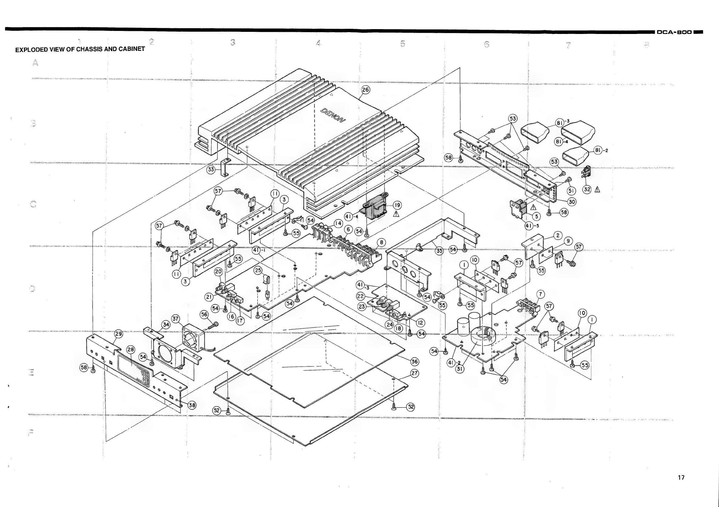
einai
|
DCA-800
m=
EXPLODED
VIEW
OF
CHASSIS
AND
CABINET
a
ee
es
ai
a
a
a
cena
atinagg
le
5
Ss
Pe
erie
nati
rcs
onronraasimsa
caiman
emnnemnan
ete
eral
Oo
Eoatarensin
>
heertrmans
Drage
s
3
;
|
:
ra
;
:
i
|
|
y
|
!
:
|
2
5
|
:
:
|
:
r
,
|
:
i
:
|
x
17
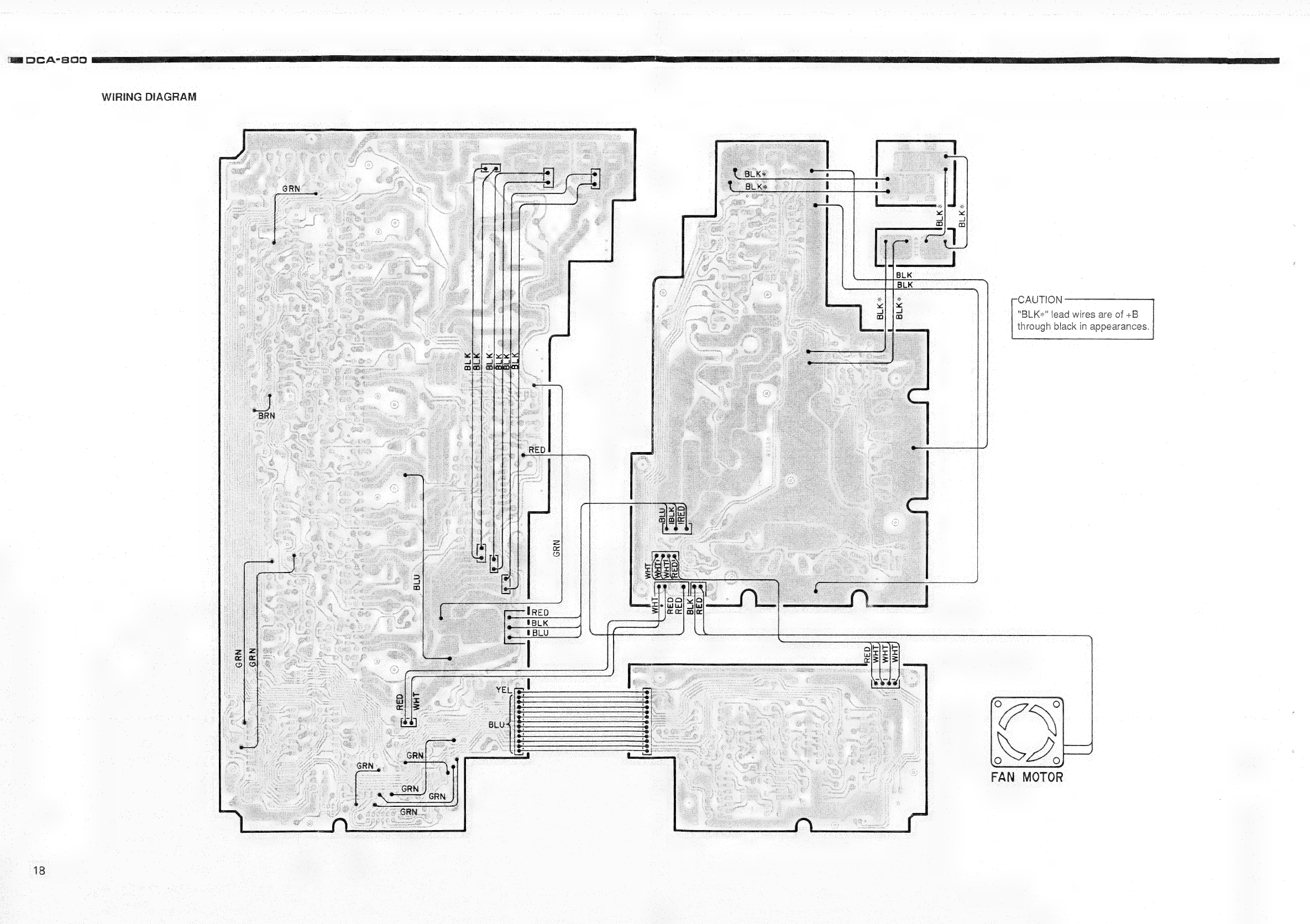
HR
DCA'S00
yaaa
en
a
ne
nn
en
en rn
i
ee
i
WIRING
DIAGRAM
CAUTION
“BLK«"
lead
wires
are
of
+B
through
black
in
appearances.
FAN
MOTOR
18

SCHEMATIC
DIAGRAM
Transistor
Diode
(Including
LED)
PJ6010
suuw
L
C60lc
330p
*F
PJ6OIb
suB
W(Q}=
BWO
Pu6
FRO!
R
oO
a
z
A
PJ6OIT
REAR
R6O2c
\k
Ic6Ol(1/2)
Ic602t1/2)
1€604
(1/2)
1C606
(1/2)
1C607(1/2)
1C603
(1/2)
1€608
(1/2)
1€604(2/2)
1C606(2/2)
1C602
(2/2)
1C603(2/2)
R6030
100k
c602c
R6O3e
100k
10/35
R6O3f
100k
IC601
(2/2)
1€607(2/2)1C608(2/2)
1C604~
608
IC60i~
603
NUM
2068
NJMO72
1c601
(1/2)
OV
R605a
100k
es
(7)
VR602
JOk(A)
1C601
~
603
1C604
~
610
NJMO72
NJM2068
1c601
(2/2)
"C6096
RGIId
0.18
12k
VR605
20k(C)
ZA
0.18
c609f
Reiit
2k
vr605
|
1c6i
172)
1c6120172)
IC60911/2)
1€612(2/2)
1€610(1/2)1C610
(1/2)
IC6I6_
IC6I5
MK
TR6Ola
TR604q
TR603q
TREOS5a
TF
TREOle
TREO4c
TR603c
TRGEOSc
TE
TR6Ole
TREO4e
TREO3e
TREOSe
TR
TR8I3
ZD806b
D602a
D60la
D602c
DEOIc
D603
D603c
D
ZD806d
D602e
D6Ole
D603e
ZD8O6F
Z0606
ZD607.
IC6II~613
iat
NJM2068
C6140
R6I6a
10/35
680
R6I90
4.7k
Ccé6l6a
l00p
TREO4c
2Sci627
VR606c
10k(B)
R623¢
4.7k
Cc6l6c
TRE04e
2SC1627
VR606e
R623e
DEOle~603e
ISS136
Q
VA
D602Z2e
DEOle
i
~2.8V2SABIT
R6l9e
47k
Ke
ALN
TREO3e
-2
R646
3.3k
Tez0K
céi90
0.1
4
R629c
C6I9c
0.1
|
R632c
10
TREOTe
|
2SKI296
R632e
10
:
TR6OTe
|
2SKi296
4
ZD607_MTZIIB
R647
o3.3k
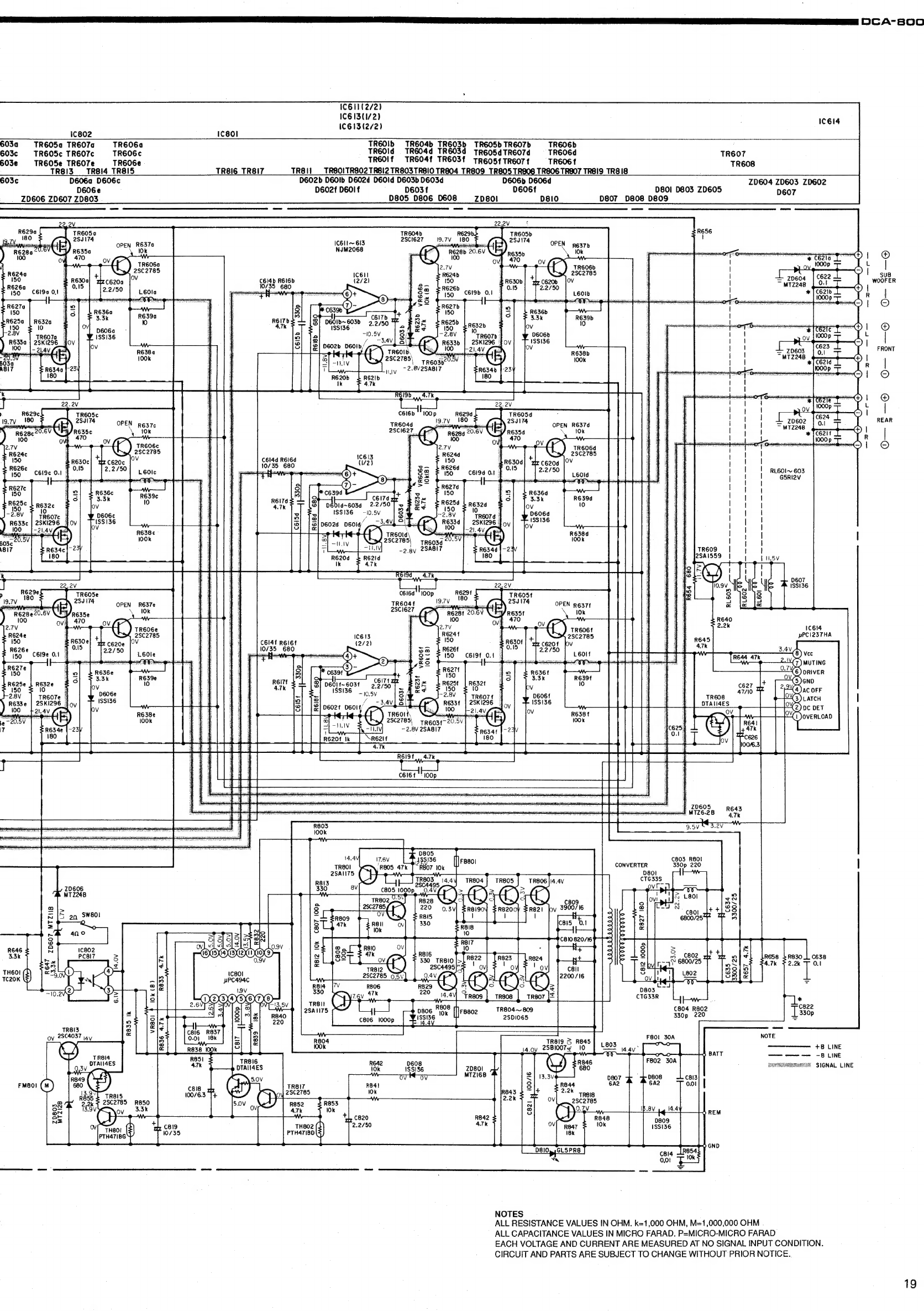
LS
NS
ETT
ETT
EL
a
EE
I
I
EL.
EL
LT
NE
SET
ETT
ET
IE
ET
LTTE
VE
I
OTE
NER
EEE
RTE
(TA
BOO
I
|
I
=
zp604
|
622
ore
|
~MTz24B
10-!
®
|
wees
|
leat
rs
J
neawneet
ld
1C611(2/2)
1C613(1/2)
1€613(2/2)
IC614
1c802
1c80!
603a
TR605a
TR607a0
TR6OGa
TREOIb
TREO4b
TR6O3b
TREO5bTR6O7b
TREOGDb
603c
TR6OS5c
TR607c
TREOGC
TR6OId
TREO4d
TR6EO3d
TREOSdTREO7d
=
TREOGd
TREOT
GO03e
TREOSe
TREO7e
TREOGE
TR6OIf
TREO4T
TREOST
TREeosStTREOTT
—
TREOGT
TREOB
TR8IZ_TR8I4
TR8IS
TR8IG_TR8IT
TR8I1
_TREOITRBO2
TRBI2
TREO3TRBIO
TR804
TR809
TR805
TRAOS
TR806
TRSO7
TRSI9
TRBIS
603¢
D606a
D606c
D602b
DEOIb
DEO2d
DEOId
DEO3b
DE03d
D606b
D606d
ZD604
ZD603
ZDG602
D606e
D602f
DEOIf
D603f
pe6o6t
D801
D803
ZD605
D607
ZD606
ZD607
ZD803
D805
D806
D608
__Zp80l
oslo
D807
D808
D809
weet,
co
“pe
IC6I1~
613
4
NJM2068
R635b
nis
Toe
OT
Git
ia
Darl
A
Qu
Sn
uae
a
511
a(t)
|
®
TR606a
1000p
i
|
28C2785
C6l4b
REIGb
10/35
C690
01
4
D601b~603b
eeice
1SSI36
2.2/50
—10.5V
f
D602b
DEOIb/
KS
treo,
NS
28C2785\
spegait
-
2.8V2SA8I7
HLALV
TR604d
2sciez7_
C614d
R6I6d
nor
I
!
:
10/35
680
Ba
|
RL6OI-~
603
c6li9c
O.1
FO”
aH
p
ee
=
RI
|
3s
|
!
G5RI2V
>
14
=
|
3
Px
ie
Resze
§
~
fed
lor
TR6O7c
3
2
|
|
2ski296_4
©
oe
£
|
by
roy
ly
I
|
H5V
D607
1SSI36
TR6O5e
280174
TR6OSF
2SJIT4
OPEN
R637t
R629e.
J
180
-
1c614
pPCI237HA
C6I4f
REIGE
10/35
680
oe
150
C6I9E
ON
0601
f~603f
1SS136
TREOTE
|
2Sk1296
28C2785|
tRE034-20-5V
~2.8V
2SABIT
|
20605
wand
MTZ6.28
PEAS
¢803
R80!
CONVERTER
330p
220
D801
CTG33S
ove
D805
Be
36
{||
Fe8o1
07
10k
C634
3300/25
R827
180
ZD607_MTZIIB
R646
3.3k
teaox
&
R812
10k
R647
3.3k
R833
4.7k
C8l2
1000p
R657
4.7k
R8I4
330
TR8II
2SANI75
CTG33R
C804
R802
TR804~
809
2SDI065
Sea
7
Lod
TREI3
<
C816
R837
28C4037
NOTE
ov
av
8
0.01.
18k
see's
3
pee
oon
+B
LINE
fy
1007e
|
2
14.9
=
al
ee
4
BATT
—
——
-8
LINE
F802
30A
eee
ee
SAVCOROREEERLE
SIGNAL
LINE
MTZI6B
:
S
REM
0809
1SSI36
D810»
;GL5PRE
Rosary
on”
cela
RBs
an
0.01
NOTES
ALL
RESISTANCE
VALUES
IN
OHM.
k=1,000
OHM,
M=1,000,000
OHM
ALL
CAPACITANCE
VALUES
IN
MICRO
FARAD.
P=MICRO-MICRO
FARAD
EACH
VOLTAGE
AND
CURRENT
ARE
MEASURED
AT
NO
SIGNAL
INPUT
CONDITION.
CIRCUIT
AND
PARTS
ARE
SUBJECT
TO
CHANGE
WITHOUT
PRIOR
NOTICE.
19
Table of contents
Other Nippon Stereo System manuals


