Nishati EXPEDITION 570 User manual

Copyright © 2020 All Rights Reserved Revision 201208
Nishati Expedition™ 570 is a 570-watt
rated ruggedized portable solar array
designed to provide power in remote
locations and expeditionary conditions.
Expedition™ 570 is fully optimized for
power output, deployed footprint,
ruggedness, transportability, complexity,
and cost. The system is ideal for use with
portable solar and hybrid power
controllers and batteries as part of a
complete solar power or charging system.
Expedition™ 570 incorporates frameless,
glass-free solar panels into an integrated
case and racking system. The self-
contained, integrated design enables
simplified array deployment by one or
two individuals in just minutes. This
system is built to military ruggedization
standards and is interoperable with
commercial and government
expeditionary solar and hybrid power
systems currently in use within the U.S.
Marine Corps and U.S. Army.
EXPEDITION™570
PORTABLE SOLAR ARRAY
OPERATIONS MANUAL
PART NUMBER:225651
Nishati, Inc.
2200 E. Williams Field Rd., Ste 200
Gilbert, Arizona 85295
703-994-2339
www.nishati-us.com
December 2020

Copyright © 2020 All Rights Reserved Revision 201012
This page intentionally left blank

Expedition™ 570 Operations Manual
i
Copyright © 2020 All Rights Reserved Revision 201208
Table of Contents
General Information.............................................................................................................. 1
Use of Special Text Boxes ...................................................................................................... 2
Background ........................................................................................................................... 3
Overview............................................................................................................................... 4
Solar Energy Basics ................................................................................................................ 5
Solar Photovoltaic (PV) Systems .....................................................................................................5
Solar Insolation and Irradiance .......................................................................................................5
Diffuse and Direct Solar Radiation ..................................................................................................6
Solar Panel Azimuth and Tilt Angle .................................................................................................6
Solar Panels and Arrays ..................................................................................................................8
Solar Array Location .......................................................................................................................8
Expedition™ 570 System Components ................................................................................... 9
Solar Array Operation –Set Up ............................................................................................ 10
Solar Array Operation –Stowing and Packing for Transport ................................................. 17
Preventive Maintenance Servicing and Checks..................................................................... 21
Provisioning Information ..................................................................................................... 23

Expedition™ 570 Operations Manual
ii
Copyright © 2020 All Rights Reserved Revision 201208
This page intentionally left blank

Expedition™ 570 Operations Manual
iii
Copyright © 2020 All Rights Reserved Revision 201208
Table of Figures
Figure 1: Expedition™ 570 Deployed...................................................................................................4
Figure 2. Solar Panel Sub-Assembly ....................................................................................................4
Figure 3: Five Expedition™ 570 Stacked on a Standard Commercial Pallet ............................................5
Figure 4. Solar Declination Angle Annual Variation..............................................................................6
Figure 5. Solar Azimuth Angle.............................................................................................................7
Figure 6. Tilt Angle Determination ......................................................................................................8
Figure 7. Four-panel Solar Array .........................................................................................................8
Figure 8: Expedition™ 570 Components ..............................................................................................9
Figure 9. Unlatch, lay out and orient the Expedition™ 570 Case Top and Bottom ...............................10
Figure 10. Un-stow Solar Panel Assemblies and lock the Solar Panel Support Tubes in place ..............11
Figure 11. Rotate the solar panels into position. ...............................................................................11
Figure 12. Secure the Solar Panel Assembly Support Straps ...............................................................12
Figure 13. Sandbag the Case Top and Bottom ...................................................................................12
Figure 14. Four Series (4s) Electrical Configuration (Standard) ...........................................................13
Figure 15. Two Series / Two Parallel (2s/2p) Electrical Configuration .................................................14
Figure 16. Making Electrical Connections ..........................................................................................14
Figure 17. Wire Harness Collector Cable Ends....................................................................................15
Figure 18. Example Expedition™ 570 Configuration with Power Electronics and Energy Storage .........16
Figure 19. Disconnect Solar Panels by Squeezing the PIO tabs ...........................................................17
Figure 20. Disconnect the Solar Panel Assembly Support Straps ........................................................18
Figure 21. Stow Solar Panel Assemblies ............................................................................................19
Figure 22. Secure Solar Panel Assemblies..........................................................................................19
Figure 23. Re-combine the Case Top and Bottom ..............................................................................20
Figure 24. Secure the Case Latches ...................................................................................................20
Figure 25. Shade Solar Panel Sub-Assemblies One Pair at a Time .......................................................22

Expedition™ 570 Operations Manual
1
Copyright © 2020 All Rights Reserved Revision 201208
General Information
Part Number 225651
Contents (4) Nishati Endurance™ 140 solar panels with Merlin™ Interconnect
(1) Rugged transport case with integrated solar panel and racking
(1) 35-foot Wire Harness Collector Cable
(16) empty sandbags
Weight 88 lbs.
Outside Dimensions 43” x 38.37” x 6.75”
Stowage Volume 6.4 cubic feet (cu. ft.)
Max Deployed Footprint 22.9 ft2(@ 35° deployment angle)
Rated Solar Power Capacity 570 Watts
PV Efficiency >19%
Open Circuit Voltage 79.6V DC (Solar Panels Wired in Series)
Short Circuit Current 9.0 Amps (A)
Operating Temperature -4° to 140° F
Storage Temperature -25° to 160° F
Weatherproofing IP67: Protected from dust / water (to 1m immersion for 30 min)
Wind Certification 50 MPH for 30 minutes with 800lbs. (400 lbs. per side)
Gust to 70 MPH when secured with 800 lbs. (400 lbs. per side)

Expedition™ 570 Operations Manual
2
Copyright © 2020 All Rights Reserved Revision 201208
Use of Special Text Boxes
WARNING
A procedure, practice, or condition that may result in injury or death if not carefully observed or
followed.
CAUTION
A procedure, practice, or condition that may damage equipment if not carefully observed or
followed.
NOTE
A procedure, practice, or condition that is essential to emphasize.

Expedition™ 570 Operations Manual
3
Copyright © 2020 All Rights Reserved Revision 201208
Background
The Nishati Expedition™ 420M Portable Solar Array, also known as the Advanced Integrated Solar Panel
Case Assembly (AISPCA), replaced conventional glass solar panels in hardened transit cases that were
originally fielded by military services. The 420-watt rated Expedition™ 420M/AISPCA dramatically
improved transportability in expeditionary operations, reducing the system weight by 52% and the
volume by 68%, while eliminating the more fragile and reflective glass and maintaining the solar
performance. Since 2015, Nishati has delivered approximately 4,500 Expedition™ 420, and its 450-watt
rated obsolescence replacement Expedition™ 450, to the U.S. Marine Corps, U.S. Army, and other
government agencies to meet remote power requirements. Many of these kits continue to be deployed
to overseas locations in support of military operations.
In 2017, Nishati introduced the Expedition™ 570 Portable Solar Array as a less complex, lower cost and
more powerful alternative to the Expedition™ 420M / 450. This system maintains the man-movable,
vehicle-transportable, and glass-free qualities, but delivers 570 watts of rated power in approximately one
half of the Expedition™ 420M/450 footprint when deployed. The Expedition™ 570 is much easier to deploy
and pack up and the simplified design improves manufacturability, field supportability and cost.
Expedition™ 570 Operations Manual
4
Copyright © 2020 All Rights Reserved Revision 201208
Overview
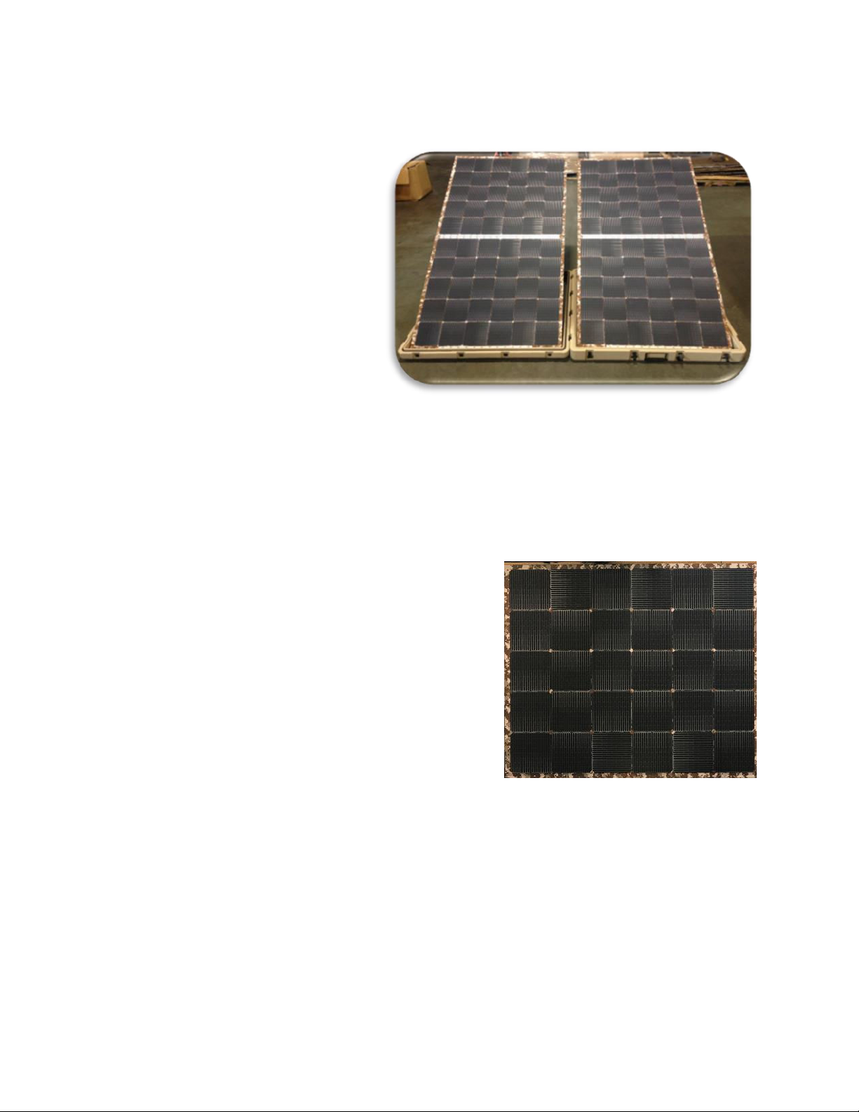
Expedition™ 570 (Figure 1) is a ruggedized
portable solar array that is compatible with
a range of ruggedized commercial-off-the-
shelf (COTS) solar, renewable, and hybrid
energy systems used by the U.S. Marine
Corps, U.S. Army, and other military,
government, and commercial systems.
Expedition™ 570 is designed for the harsh
operational and environmental conditions
encountered in the field. This equipment is
intended for transport by military ground,
air, and sea vehicles and to be moved
frequently by personnel.
Expedition™ 570 consists of 4 frameless glass-free rigid 142-watt rated Nishati Endurance 140 solar
modules (Figure 2) within a ruggedized case, which also serves as the base of the portable ground-
mounted rack/support system. Each of the four solar panels incorporate 3 bypass diodes to mitigate
power-loss from partial shading and to protect the panel against reverse current flow for a total of 12
diodes per array.
Solar panels are joined in pairs by a hinge assembly and the
pairs deploy side by side supported by the integrated rack and
case system at a 35fixed angle. In the standard system
configuration, the four solar modules are connected
electrically in series. An option to connect each pair in series
and then connect the pairs in parallel is available for working
with solar controllers that are unable to accept the series
open-circuit voltage of 79.6V. Each module pair with racking
folds down to fit within their respective case halves, which
then clasp together to form the transport configuration. (16)
sandbags (empty) and one 35-foot Export Power Cable are
included with the standard kit. Tie down straps and stakes may be added to the kit as an option. The
system is equipped with multiple carrying handles to permit single or two-person movement and two-
person lift.
The complete system measures 43.0” x 38.4” x 6.75” in the transport configuration and weighs 88 lbs. The
system deploys in a surface area of less than 23 ft2(86” x 38.4”). Systems can be stacked up to eight high
for palletized transport and can be stacked vertically on their edge for trailer or other space-constrained
transport provided there is a means to secure them.
Figure 1: Expedition™ 570 Deployed
Figure 2. Solar Panel Sub-Assembly

Expedition™ 570 Operations Manual
5
Copyright © 2020 All Rights Reserved Revision 201208
Solar Energy Basics
Solar Photovoltaic (PV) Systems
PV systems are designed to harvest energy directly from sunlight. PV systems often include solar panels,
batteries, power control electronics, and accessories that enable power applications.
Solar Insolation and Irradiance
Solar insolation is the amount of solar radiation received on a given surface area during a given timeframe.
It is used as a measure of how much energy from the sun is striking a location on the earth’s surface over
a given time and, hence, available for harvesting. It is typically denoted as watts per hour per square
meter. The amount of insolation received at the surface of the Earth is controlled by the angle of the sun,
the state of the atmosphere, altitude, and geographic location. Solar irradiance is a measure of how much
solar power is available at a specific location and time. On a clear day with the sun’s rays directly
perpendicular to a surface the solar irradiance is about 1,000 watts per square meter (W/m2), which is
also known as one 1.0 sun. Terrestrial solar panel power ratings reference standard test conditions (STC)
of 1,000 W/m2, 25C and air mass spectrum 1.5 (AM1.5).
PV modules harvest solar radiation and produce direct current (DC) electricity. PV modules are most
productive when the panels face directly into the sun (i.e. are as close to perpendicular to the sun’s rays
as practical). Two factors affect the angle at which the sun’s rays strike a solar panel:
•Direction / azimuth
•Tilt angle
Figure 3: Five Expedition™ 570 Stacked on a Standard Commercial Pallet

Expedition™ 570 Operations Manual
6
Copyright © 2020 All Rights Reserved Revision 201208
Diffuse and Direct Solar Radiation
As sunlight passes through the atmosphere, some of it is absorbed, scattered, and reflected by:
The result is diffuse solar radiation, which contains less concentrated solar energy. The solar radiation that
reaches the Earth's surface without being diffused is called direct beam solar radiation. The sum of the
diffuse and direct solar radiation is called global solar radiation. Atmospheric conditions can reduce direct
beam radiation by 10% on clear, dry days and by 100% during heavily clouded days.
Solar Panel Azimuth and Tilt Angle
Solar Declination Angle (), or Declination, is the angle between the equator and a line drawn from the
center of the Earth to the center of the sun. Declination varies based on the time of year due to earth’s
tilt, oscillating between 23.45north of the equator on June 21st and 23.45south of the equator on
December 21st (Figure 4). Azimuth is the angle along the horizon with zero degrees corresponding to
North and increasing in a clockwise fashion (when viewed from above) such that 90is East, 180is South,
and 270is West. Solar Azimuth Angle is the sun’s azimuth (Figure 5).
•
Air molecules
•Water vapor
•Clouds
•
Dust
•Pollutants
•
Forest fires
•Volcanoes
[Source: PVEducation.org]
Figure 4. Solar Declination Angle Annual Variation

Expedition™ 570 Operations Manual
7
Copyright © 2020 All Rights Reserved Revision 201208
At latitudes north of the sun’s Declination for a given day, the apparent Solar Azimuth Angle changes
throughout daylight hours from east to west through true South. At latitudes south of the sun’s
Declination, the apparent Solar Azimuth Angle changes from east to west through true North. Since most
Northern Hemisphere latitudes are north and most Southern Hemisphere latitudes are south of the sun’s
Declination for most of the year, a rule of thumb can be used for optimal fixed solar panel azimuth. That
is, in most locations at most times of the year solar panels and arrays should be emplaced facing true (not
magnetic) South in the northern hemisphere and true North in the southern hemisphere.
When using portable solar systems, it is possible to make fine adjustments to more closely track the sun
based on location, time of year, and even time of day. It may also be helpful to compensate for local
environmental effects. For example, in a valley with mountains to the west, facing solar panels slightly
east of true South to collect extra power during the morning can compensate for losing power in the
afternoon from the mountain shading.
NOTE
If the environmental effects and proper azimuth are uncertain, the system should remain facing
true South (in the northern hemisphere) or true North (in the southern hemisphere).
Tilt angle refers to the PV panel’s vertical angle relative to the ground. Optimum tilt angle is a function of
the sun’s elevation relative to the horizon at the location of interest on the earth at any given time. Once
a panel is aligned to the proper azimuth, the tilt angle is determined. Optimum tilt angle is determined by
latitude, solar declination angle (i.e. time of year) and time of day.
For a fixed solar panel system, a general year-round rule is to set tilt angle equal to the latitude. For
example, at the north and south poles, the latitude will equal 90°. At 45° North or South latitude, the tilt
angle of the solar panels should be 45°, and at the equator the solar panels should be laid flat. Figure 6
depicts this rule of thumb.
[Source: PVEducation.org]
Figure 5. Solar Azimuth Angle

Expedition™ 570 Operations Manual
8
Copyright © 2020 All Rights Reserved Revision 201208
If the solar panels have an adjustable tilt angle, adjust as follows:
•Winter –latitude plus fifteen degrees
•Summer –latitude minus fifteen degrees
Solar Panels and Arrays
Solar panels, also referred to as solar modules, are made up of multiple electrically connected solar cells.
Solar arrays, in turn, consist of a several solar panels, which are electrically connected in series, parallel,
or a combination of series and parallel circuits. Figure 7
shows linked solar panels in a solar array.
Most solar panels produce a relatively low amount of
voltage and amperage. Depending on load
requirements, multiple solar panels can be used
together, creating a solar array, to reach the desired
energy production. This allows tailored solar energy
production to match load requirements.
Solar Array Location
Solar arrays shall be located away from flammable materials and away from tents or shelters. In very rare
cases solar energy systems have been known to cause fires due to internal electrical failures. It is
important to handle solar energy systems with care.
WARNING
Solar systems are silent energy systems. Always assume live voltage is present.
WARNING
Solar energy systems should be handled like other power generation equipment and shall not be
located near flammable materials or close to tents or shelters.
Figure 6. Tilt Angle Determination
Figure 7. Four-panel Solar Array


Expedition™ 570 Operations Manual
10
Copyright © 2020 All Rights Reserved Revision 201208
Solar Array Operation –Set Up
1. Opening the Case and Orienting the Solar Array
1a. Lay the Expedition™ 570 solar array on the ground or other flat solid surface with the Case Bottom
to the ground side. The Case Bottom is slightly deeper than the Case Top and distinguished by carrying
handles and butterfly latches around the case exterior perimeter.
1b. Unlatch the Case Assembly side latches by turning the butterfly handle of each latch
counterclockwise until tension is released then folding the handle flush and rotating the latch and hand
downward until flush with the Case Bottom.
CAUTION
Latch butterfly handles should remain flush with the latch and case except when being turned to
open or secure the case. Failing to maintain the latch handles flush during use and movement
may result in damage to the latch.
1c. Separate the Case Top from the Case Bottom by grasping the Case Top lip and lifting it free, and
then rotating to place on the ground next to the Case Bottom with the stowed solar payload facing
upward. The lower solar panel hinges that connect each set of joined Solar Panel Sub-Assemblies to the
Case should be placed toward the intended solar panel azimuth. (Figure 9)
Figure 9. Unlatch, lay out and orient the Expedition™ 570 Case Top and Bottom
Storage Strap
“E”Hooks
Case front
toward
recommended
solar azimuth

Expedition™ 570 Operations Manual
11
Copyright © 2020 All Rights Reserved Revision 201208
2. Erecting the Solar Panels
2a. Starting with either the Case Top or Bottom, unclasp the Solar Panel Storage Straps by slipping
the strap loop of each of the front straps free from the rear strap “E” hooks. Raise the folded panels and
grasp the Solar Panel Support Tube as it swings free. Pivot the bracket to the case rear, placing the bracket
base against the back wall of the case. Repeat this step for the other Case half. (Figure 10)
2b. Starting with either the Case Top or Bottom, rotate the upper Solar Panel Assembly to a position
in plane with the lower Solar Panel Assembly. Repeat for the other Case half. (Figure 11)
Figure 10. Un-stow Solar Panel Assemblies and lock the Solar Panel Support Tubes in
place
Storage Straps
Disconnected
Figure 11. Rotate the solar panels into position.

Expedition™ 570 Operations Manual
12
Copyright © 2020 All Rights Reserved Revision 201208
3. Securing the Solar Panels
3a. Secure all four Support Straps by stretching the straps just enough to join them and sliding the
upper strap loop over the open end of the opposing lower strap “E” hook. (Figure 12)
WARNING
Failure to secure solar panel Support Straps could result in damage, death, or injury.
3b. Secure each Expedition™ 570 Case Assembly with (16) 50 lb. sandbags using (8) sandbags per
case half, as shown in Figure 13.
WARNING
Failure to properly secure solar array to surface with sandbags could result in damage, death, or
injury in high winds.
Figure 13. Sandbag the Case Top and Bottom
Figure 12. Secure the Solar Panel Assembly Support Straps

Expedition™ 570 Operations Manual
13
Copyright © 2020 All Rights Reserved Revision 201208
4. Electrically Connecting the Expedition™ 570 Solar Array
4a. Prior to connecting any solar panels to power electronics or a load, electrically connect the four
solar panels as required to remain within power electronics voltage limits. The standard system
configuration is a four-panel string in series (4s) connection. An alternate configuration that connects the
Solar Panel Sub-assemblies into series pair (2s) strings within each Solar Panel Assembly and then connects
these two strings/Solar Panel Assemblies in parallel (2p) is also possible. The 2s/2p configuration requires
a cable or controller with diode protection between parallel circuits to prevent electrical current feeding
from one Solar Panel Assembly into the other in the event of a voltage mismatch between them caused
by differential sun exposure or a malfunction. Nishati offers an optional diode-protected ‘Y’ cable for the
2s/2p configuration.
•4 Series (4s) Connection (Figure 14). At STC, the 4s connection provides a typical voltage of 79.7VOC
(open circuit) when not under load and 65.2V under load. In this configuration, the average current
delivered by the array under load is 8.72A.
•2 Series/2 Parallel (2s/2p) Connection (Figure 15). At STC, the 2s/2p connection provides a typical
voltage of 39.8V (open circuit) when not under load and 32.6V under load. In this configuration, the
average current delivered by the array under load is 17.4A.
4b. As required for the desired configuration, connect the positive (male) and negative (female) H4
connectors between solar panels by joining the male and female ends until they click together securely.
(Figure 16).
4c. Once the panel string is connected in series, connect the free positive and negative H4 connectors
to the opposing male or female H4 connection of the Wire Harness Collector Cable.
Figure 14. Four Series (4s) Electrical Configuration (Standard)

Expedition™ 570 Operations Manual
14
Copyright © 2020 All Rights Reserved Revision 201208
CAUTION
Prior to connecting the Expedition™ 570 to a solar charge controller or other power electronics,
verify that controller/electronics are rated to accept at least the open-circuit voltage and short-
circuit current for the selected wiring configuration. Solar array inputs that exceed controller
power ratings may result in damage to the controller electronics.
CAUTION
The 2s/2p configuration requires adequately rated blocking diode protection between parallel
solar panel circuits (strings). Connecting the array in a 2s/2p configuration without this protection
creates a risk of panel damage and failure.
WARNING
Failure to properly secure electrical connectors could result in shock hazard to personnel.
Negative (Female) H4 Connector
Figure 16. Making Electrical Connections
Positive (Male) H4 Connector
Figure 15. Two Series / Two Parallel (2s/2p) Electrical Configuration

Expedition™ 570 Operations Manual
15
Copyright © 2020 All Rights Reserved Revision 201208
5. Connecting Expedition™ 570 to a Solar Controller (Standard Configuration)
5a. After connecting the solar panel electrical connectors in a 4s configuration there will be two
unconnected wires, one a positive (male) connector and one a negative (female) connector. A best
practice for cable management is to make connections so that the free ends originate from the lower solar
panels as shown in Figure 14.
5b. Connect the Wire Harness Collector Cable ‘Y’ end female and male H4 connectors to the male
and female H4 connectors from the solar array. Figure 17 shows the Wire Harness connectors.
5c. Connect the Wire Harness to the solar controller. The standard Wire Harness terminates with an
ITT Cannon 2 Contact Bayonet female connector (P/N CA3106F20-23SB) that is intended to mate with a
male connector (CA3106E20-23SB) on the controller. The plug type can be modified at the factory or by
qualified personnel in the field to adapt to other solar and hybrid controllers. To connect the standard
harness, align the nubs on the Harness connector coupling nut with the slotted threads on the controller’s
solar input connector and twist clockwise until the connectors fully seat and lock together with a click.
5d. Connect additional Expedition™ 570 arrays in the same manner, as desired and as the controller
permits. Figure 18 shows an example configuration with four Expedition™ 570 inputs.
Figure 17. Wire Harness Collector Cable Ends
‘Y’end
connectors
Cannon
connector
This manual suits for next models
1
Table of contents
Other Nishati Solar Panel manuals

Popular Solar Panel manuals by other brands

Solarbayer
Solarbayer NANOSOL 135 Product information

Erco
Erco ES-650PIA Original Operator's Manual

Sunforce
Sunforce 130 WATT CRYSTALLINE SOLAR PANEL user manual

winees
winees L1 quick start guide

NEO TOOLS
NEO TOOLS 90-141 user manual

Harbor Freight Tools
Harbor Freight Tools 62443 Owner's manual & safety instructions


EcoFlow
EcoFlow 160W user manual

Steinbach
Steinbach speedsolar Sun 00-49120 manual

EcoFlow
EcoFlow 100 W Flexible Solar Panel user manual

Viessmann
Viessmann Vitosol 200-T Service instructions for contractors

Panasonic
Panasonic HIT VBHN330SA16 General installation manual

Ganz
Ganz GSP-06 GENERAL INSTALLATION & USER MANUAL