Nissindo LX-4040U Owner's manual
LX-4040U
MULTI-CHANNEL
PROFESSIONAL
WIRELESS MICROPHONE
GETTO THE POINT
POWER
ANTENNA-A ANTENNA-B
Channel-1
UHF WIRELESS RECEIVER MODULE
UHF
POWER RF AF
SQ MIN MAX
Channel-2
UHF WIRELESS RECEIVER MODULE
UHF
POWER RF AF
SQ MIN MAX
Channel-3
UHF WIRELESS RECEIVER MODULE
UHF
POWER RF AF
SQ MIN MAX
Channel-4
UHF WIRELESS RECEIVER MODULE
UHF
POWER RF AF
SQ MIN MAX
Model: LX-4040U Four Handheld Dynamic
UHF Wireless Microphone System
Installation and Operation
Free Style
Techniques UHF Wireless
For Singing Microphone
Karaoke System
Model: LX-4040U Four Handheld Dynamic
UHF Wireless Microphone System
Installation and Operation
Free Style
Techniques UHF Wireless
For Singing Microphone
Karaoke System
LX-4040U
MULTI-CHANNEL
PROFESSIONAL
WIRELESS MICROPHONE
GETTO THE POINT
POWER
ANTENNA-A ANTENNA-B
Channel-1
UHF WIRELESS RECEIVER MODULE
UHF
POWER RF AF
SQ MIN MAX
Channel-2
UHF WIRELESS RECEIVER MODULE
UHF
POWER RF AF
SQ MIN MAX
Channel-3
UHF WIRELESS RECEIVER MODULE
UHF
POWER RF AF
SQ MIN MAX
Channel-4
UHF WIRELESS RECEIVER MODULE
UHF
POWER RF AF
SQ MIN MAX
BAT LOW
ON
OFF
BAT LOW
ON
OFF
BAT LOW
ON
OFF
BAT LOW
ON
OFF

AUDIO-OUT
www.nissindousa.com
Nissindo Trademark All Right Reserved.
Engineered And Design In U.S.A.
Model: LX-4040U
Serial:
GET TO THE POINT
POWER-IN
DC: 13V-18V
500mA
CH.1, 2, 3, 4
Mixed 1/4
Channel-4
XLR
Channel-3
XLR
Channel-2
XLR
Channel-1
XLR
Channel-1:___________________
Channel-2:___________________
Channel-3:___________________
Channel-4:___________________
UHF FREQUENCY
32
CONTENTS
INTRODUCTION......................................................................................................................................... 2
RECEIVER DESCRIPTION..................................................................................................................3~4
HOW TO CONNECT RECEIVER OUTPUTS........................................................................... 5
UHF WIRELESS SYSTEM CHART....................................................................................................... 5
DC POWER CONNECTION............................................................................................................... 6
HANDHELD TRANSMITTER DESCRIPTION............................................................................ 7
HOW TO INSERT HANDHELD TRANSMITTER’S BATTERIES.................................... 8
HOW TO TURN ON AND OFF HANDHELD TRANSMITTER...................................9
RECEIVER FUNCTIONS............................................................................................................................9
TIE-CLIP TRANSMITTER SPECIFICATION (optional sale)............................................... 10
TECHNICAL FEATURES........................................................................................................................ 11
PRECAUTION.............................................................................................................................................. 12
LX-4040U FCC FREQUENCY............................................................................................................ 12
FREQUENCY SCAN GROUPS FOR BAND C & BAND D............................................13
US UHF WIRELESS OPERATING FREQUENCIES....................................................... 14~15
INTRODUCTION
As a leader in the Karaoke market, Nissindo again provides our customers a
new 4 channels UHF wireless microphone system LX-4040U with the latest
Karaoke technology. This latest model replaces the old VHF wireless microphone
technology. By using UHF it can reduce the interference from other radio
frequency for clearer vocal. You may use 4 microphones at the same time or
replace them with bodypaks or headsets.
This new wireless microphone system comes with 4 microphones for multiple
singing, it can really crank up a party. With 4 people singing at a time it gives you a
band performance. Along with noise prevention technology you won’t feel
embarrassed again by bad noise from your microphone.
We, at Nissindo (USA), would like to thank you for buying our microphone
products. Please follow the instructions in our manual, so you can make the best
use of this system.
DESCRIPTIONS:
1. Front panel that allows you to check AF (audio frequency) and RF
(radio frequency) signal.
2. Receiver Sensitivity adjustable for different environmental conditions.
3. Reduce noise and enhances vocal quality.
4. Wide dynamic range audio frequency.
5. Adjustable antennas for different angles to receive better signals.
6. Built with mountable rack for DJ cases. (19” install to case)
7. 13 different frequencies. (Nontunable)
RECEIVER DESCRIPTION
NAMES & FUNCTION:
Front Panel:
1. Channel-1 SQ adjustor.
2. Channel-1 volume adjustor.
3. Power switch On/Off.
4. Antenna A Input for Channel 1 & 2. (BNC socket.)
5. Power LED: on/off (red bulb.)
6. RF LED: Radio frequency signal for Microphone Channel-1. (Orange bulb)
7. AF LED: Microphone signal indicator for Channel-1. (Green bulb)
8. Channel-2 Display Panel (Refer to 1, 2, 5-7)
9. Channel-3 Display Panel (Refer to 1, 2, 5-7)
10. Channel-4 Display Panel (Refer to 1, 2, 5-7)
11. Antenna B Input for Channel 3 & 4. (BNC socket.)
Rear Panel:
9. Channel-4 XLR balanced audio output 50Hz~15KHz +/-3dB.
10. Channel-3 XLR balanced audio output 50Hz~15KHz +/-3dB.
11. Channel-2 XLR balanced audio output 50Hz~15KHz +/-3dB.
12. Channel-1 XLR balanced audio output 50Hz~15KHz +/-3dB.
13. Power supply dock with removable IEC cable 13V~18V / 500mA.
14. Channel-1, 2, 3 & 4 1/4-inch (6.3 mm) Jack socket unbalanced audio output,
Mixed (channel-1, 2, 3 & 4) microphone audio output will effect all 4
channels. If you would like to control each microphone’s tone or effect,
please connect XLR balanced microphone audio output.
Channel-2
UHF WIRELESS RECEIVER MODULE
UHF
SQ
POWER RF AF
MIN MAX
Channel-3
UHF WIRELESS RECEIVER MODULE
UHF
SQ
POWER RF AF
MIN MAX
Channel-4
UHF WIRELESS RECEIVER MODULE
UHF
SQ
POWER RF AF
MIN MAX
Channel-1
UHF WIRELESS RECEIVER MODULE
UHF
SQ
POWER RF AF
MIN MAX
LX-4040U
MULTI-CHANNEL
PROFESSIONAL
WIRELESS MICROPHONE
GETTO THE POINT
POWER
ANTENNA-A ANTENNA-B
4 8 9 10 11
1
2 3
65 7
13 14
9 10 11 12

AUDIO-OUT
Comments? [email protected]
www.nissindousa.com
Nissindo Trademark All Right Reserved.
Engineered And Design In U.S.A.
Model: LX-4040U
Serial:
GET TO THE POINT
POWER-IN
DC: 13V-18V
500mA
CH.1, 2, 3, 4
Mixed 1/4
Channel-4
XLR
Channel-3
XLR
Channel-2
XLR
Channel-1
XLR
Channel-1:___________________
Channel-2:___________________
Channel-3:___________________
Channel-4:___________________
UHF FREQUENCY
32
CONTENTS
INTRODUCTION......................................................................................................................................... 2
RECEIVER DESCRIPTION..................................................................................................................3~4
HOW TO CONNECT RECEIVER OUTPUTS........................................................................... 5
UHF WIRELESS SYSTEM CHART....................................................................................................... 5
DC POWER CONNECTION............................................................................................................... 6
HANDHELD TRANSMITTER DESCRIPTION............................................................................ 7
HOW TO INSERT HANDHELD TRANSMITTER’S BATTERIES.................................... 8
HOW TO TURN ON AND OFF HANDHELD TRANSMITTER...................................9
RECEIVER FUNCTIONS............................................................................................................................9
TIE-CLIP TRANSMITTER SPECIFICATION (optional sale)............................................... 10
TECHNICAL FEATURES........................................................................................................................ 11
PRECAUTION.............................................................................................................................................. 12
LX-4040U FCC FREQUENCY............................................................................................................ 12
FREQUENCY SCAN GROUPS FOR BAND C & BAND D............................................13
US UHF WIRELESS OPERATING FREQUENCIES....................................................... 14~15
INTRODUCTION
As a leader in the Karaoke market, Nissindo again provides our customers a
new 4 channels UHF wireless microphone system LX-4040U with the latest
Karaoke technology. This latest model replaces the old VHF wireless microphone
technology. By using UHF it can reduce the interference from other radio
frequency for clearer vocal. You may use 4 microphones at the same time or
replace them with bodypaks or headsets.
This new wireless microphone system comes with 4 microphones for multiple
singing, it can really crank up a party. With 4 people singing at a time it gives you a
band performance. Along with noise prevention technology you won’t feel
embarrassed again by bad noise from your microphone.
We, at Nissindo (USA), would like to thank you for buying our microphone
products. Please follow the instructions in our manual, so you can make the best
use of this system.
DESCRIPTIONS:
1. Front panel that allows you to check AF (audio frequency) and RF
(radio frequency) signal.
2. Receiver Sensitivity adjustable for different environmental conditions.
3. Reduce noise and enhances vocal quality.
4. Wide dynamic range audio frequency.
5. Adjustable antennas for different angles to receive better signals.
6. Built with mountable rack for DJ cases. (19” install to case)
7. 13 different frequencies. (Nontunable)
RECEIVER DESCRIPTION
NAMES & FUNCTION:
Front Panel:
1. Channel-1 SQ adjustor.
2. Channel-1 volume adjustor.
3. Power switch On/Off.
4. Antenna A Input for Channel 1 & 2. (BNC socket.)
5. Power LED: on/off (red bulb.)
6. RF LED: Radio frequency signal for Microphone Channel-1. (Orange bulb)
7. AF LED: Microphone signal indicator for Channel-1. (Green bulb)
8. Channel-2 Display Panel (Refer to 1, 2, 5-7)
9. Channel-3 Display Panel (Refer to 1, 2, 5-7)
10. Channel-4 Display Panel (Refer to 1, 2, 5-7)
11. Antenna B Input for Channel 3 & 4. (BNC socket.)
Rear Panel:
9. Channel-4 XLR balanced audio output 50Hz~15KHz +/-3dB.
10. Channel-3 XLR balanced audio output 50Hz~15KHz +/-3dB.
11. Channel-2 XLR balanced audio output 50Hz~15KHz +/-3dB.
12. Channel-1 XLR balanced audio output 50Hz~15KHz +/-3dB.
13. Power supply dock with removable IEC cable 13V~18V / 500mA.
14. Channel-1, 2, 3 & 4 1/4-inch (6.3 mm) Jack socket unbalanced audio output,
Mixed (channel-1, 2, 3 & 4) microphone audio output will effect all 4
channels. If you would like to control each microphone’s tone or effect,
please connect XLR balanced microphone audio output.
Channel-2
UHF WIRELESS RECEIVER MODULE
UHF
SQ
POWER RF AF
MIN MAX
Channel-3
UHF WIRELESS RECEIVER MODULE
UHF
SQ
POWER RF AF
MIN MAX
Channel-4
UHF WIRELESS RECEIVER MODULE
UHF
SQ
POWER RF AF
MIN MAX
Channel-1
UHF WIRELESS RECEIVER MODULE
UHF
SQ
POWER RF AF
MIN MAX
LX-4040U
MULTI-CHANNEL
PROFESSIONAL
WIRELESS MICROPHONE
GETTO THE POINT
POWER
ANTENNA-A ANTENNA-B
4 8 9 10 11
1
2 3
65 7
13 14
9 10 11 12

LX-4040U
MULTI-CHANNEL
PROFESSIONAL
WIRELESS MICROPHONE
GET TO THE POINT
ANTENNA-A
4
RECEIVER DESCRIPTION
SETTING UP YOUR RECEIVER:
1. The package comes with two antennas, a receiver, one AC power
adaptor, one audio cable, four 9V battery, and four microphones.
2. Screw the antennas (BNC socket) into the back panel of the
receiver and turn it in clockwise to lock it as shown in the following
diagram. You can adjust the antennas to angle differently for
adjusting signal strenghts.
5
HOW TO CONNECT RECEIVER OUTPUTS
There are 5 different connectors as shown in the following diagram:
A. Mixed channel audio output (for all microphone channels)
B. Channel-4 3-Pin XLR balanced audio output.
C. Channel-3 3-Pin XLR balanced audio output.
D. Channel-2 3-Pin XLR balanced audio output.
E. Channel-1 3-Pin XLR balanced audio output.
A. Is an unbalanced audio out. If you connect the mixed out to the mixer or
amplifier, and change effects all microphones will have the same effects. Enables
the use for all 4 microphones.
B. Balanced XLR for Channel 4. Enables usage of Microphone 4.
C. Balanced XLR for Channel 3. Enables usage of Microphone 3.
D. Balanced XLR for Channel 2. Enables usage of Microphone 2.
E. Balanced XLR for Channel 1. Enables usage of Microphone 1.
UHF WIRELESS SYSTEM CHART
Audio Mixer Amplifier or a Karaoke Unit Input terminal
XLR
Balance Input
XLR
Balance Input
XLR
Balance Input
XLR
Balance Input
1/4"
Unbalance Input
1/4"
Unbalance Input
1/4"
Unbalance Input 1/4"
Unbalance Input
XLR Balanced Connection
AUDIO-OUT
www.nissindousa.com
Nissindo Trademark All Right Reserved.
Engineered And Design In U.S.A.
Model: LX-4040U
Serial:
GET TO THE POINT
POWER-IN
DC: 13V-18V
500mA
CH.1, 2, 3, 4
Mixed 1/4
Channel-4
XLR
Channel-3
XLR
Channel-2
XLR
Channel-1
XLR
A B C D E
Rear View
AUDIO-OUT
www.nissindousa.com
Nissindo Trademark All Right Reserved.
Engineered And Design In U.S.A.
Model: LX-4040U
Serial:
GET TO THE POINT
POWER-IN
DC: 13V-18V
500mA
CH.1, 2, 3, 4
Mixed 1/4
Channel-4
XLR
Channel-3
XLR
Channel-2
XLR
Channel-1
XLR
NOTE
9V Battery: 4 pieces
AC Power
Adapter: 1 Unit
Receiving
Antenna:
2 Units
Audio Cable (For mixed out): 1 Unit
Handheld Transmitter: 4 Set
BAT LOW
ON
OFF
BAT LOW
ON
OFF
BAT LOW
ON
OFF
BAT LOW
ON
OFF
Receiver: 1 Set
GETTO THE POINT
POWER
ANTENNA-A ANTENNA-B
Channel-1
UHF WIRELESS RECEIVER MODULE
UHF
POWER RF AF
SQ MIN MAX
Channel-2
UHF WIRELESS RECEIVER MODULE
UHF
POWER RF AF
SQ MIN MAX
Channel-3
UHF WIRELESS RECEIVER MODULE
UHF
POWER RF AF
SQ MIN MAX
Channel-4
UHF WIRELESS RECEIVER MODULE
UHF
POWER RF AF
SQ MIN MAX
LX-4040U
MULTI-CHANNEL
PROFESSIONAL
WIRELESS MICROPHONE
8.43 inches
21.4 cm
9 V
ALKALINE
BATTERY

LX-4040U
MULTI-CHANNEL
PROFESSIONAL
WIRELESS MICROPHONE
GET TO THE POINT
ANTENNA-A
4
RECEIVER DESCRIPTION
SETTING UP YOUR RECEIVER:
1. The package comes with two antennas, a receiver, one AC power
adaptor, one audio cable, four 9V battery, and four microphones.
2. Screw the antennas (BNC socket) into the back panel of the
receiver and turn it in clockwise to lock it as shown in the following
diagram. You can adjust the antennas to angle differently for
adjusting signal strenghts.
5
HOW TO CONNECT RECEIVER OUTPUTS
There are 5 different connectors as shown in the following diagram:
A. Mixed channel audio output (for all microphone channels)
B. Channel-4 3-Pin XLR balanced audio output.
C. Channel-3 3-Pin XLR balanced audio output.
D. Channel-2 3-Pin XLR balanced audio output.
E. Channel-1 3-Pin XLR balanced audio output.
A. Is an unbalanced audio out. If you connect the mixed out to the mixer or
amplifier, and change effects all microphones will have the same effects. Enables
the use for all 4 microphones.
B. Balanced XLR for Channel 4. Enables usage of Microphone 4.
C. Balanced XLR for Channel 3. Enables usage of Microphone 3.
D. Balanced XLR for Channel 2. Enables usage of Microphone 2.
E. Balanced XLR for Channel 1. Enables usage of Microphone 1.
UHF WIRELESS SYSTEM CHART
Audio Mixer Amplifier or a Karaoke Unit Input terminal
XLR
Balance Input
XLR
Balance Input
XLR
Balance Input
XLR
Balance Input
1/4"
Unbalance Input
1/4"
Unbalance Input
1/4"
Unbalance Input 1/4"
Unbalance Input
XLR Balanced Connection
AUDIO-OUT
Comments? [email protected]
www.nissindousa.com
Nissindo Trademark All Right Reserved.
Engineered And Design In U.S.A.
Model: LX-4040U
Serial:
GET TO THE POINT
POWER-IN
DC: 13V-18V
500mA
CH.1, 2, 3, 4
Mixed 1/4
Channel-4
XLR
Channel-3
XLR
Channel-2
XLR
Channel-1
XLR
A B C D E
Rear View
AUDIO-OUT
Comments? [email protected]
www.nissindousa.com
Nissindo Trademark All Right Reserved.
Engineered And Design In U.S.A.
Model: LX-4040U
Serial:
GET TO THE POINT
POWER-IN
DC: 13V-18V
500mA
CH.1, 2, 3, 4
Mixed 1/4
Channel-4
XLR
Channel-3
XLR
Channel-2
XLR
Channel-1
XLR
NOTE
9V Battery: 4 pieces
AC Power
Adapter: 1 Unit
Receiving
Antenna:
2 Units
Audio Cable (For mixed out): 1 Unit
Handheld Transmitter: 4 Set
BAT LOW
ON
OFF
BAT LOW
ON
OFF
BAT LOW
ON
OFF
BAT LOW
ON
OFF
Receiver: 1 Set
GETTO THE POINT
POWER
ANTENNA-A ANTENNA-B
Channel-1
UHF WIRELESS RECEIVER MODULE
UHF
POWER RF AF
SQ MIN MAX
Channel-2
UHF WIRELESS RECEIVER MODULE
UHF
POWER RF AF
SQ MIN MAX
Channel-3
UHF WIRELESS RECEIVER MODULE
UHF
POWER RF AF
SQ MIN MAX
Channel-4
UHF WIRELESS RECEIVER MODULE
UHF
POWER RF AF
SQ MIN MAX
LX-4040U
MULTI-CHANNEL
PROFESSIONAL
WIRELESS MICROPHONE
8.43 inches
21.4 cm
9 V
ALKALINE
BATTERY

9V
BAT LOW
ON
OFF
GETTO THE POINT
POWER
ANTENNA-A ANTENNA-B
Channel-1
UHF WIRELESS RECEIVER MODULE
UHF
POWER RF AF
SQ MIN MAX
Channel-2
UHF WIRELESS RECEIVER MODULE
UHF
POWER RF AF
SQ MIN MAX
Channel-3
UHF WIRELESS RECEIVER MODULE
UHF
POWER RF AF
SQ MIN MAX
Channel-4
UHF WIRELESS RECEIVER MODULE
UHF
POWER RF AF
SQ MIN MAX
LX-4040U
MULTI-CHANNEL
PROFESSIONAL
WIRELESS MICROPHONE
6 7
HANDHELD TRANSMITTER (Wireless Mic.)
DESCRIPTION
TRANSMITTER DETAILS:
Uncovered Looking of the Handheld Transmitter:
1. Condenser and grille.
2. Batter power indicator: if light is flashing, battery is low, if light is on and not
flashing battery power is at normal level. No light means power off or no
power.
3. Easily-accessible power switch ON/OFF.
4. Battery dock: battery cover unscrews for access to the 9V battery rechargeable.
5. Variable battery cover.
DC-POWER CONNECTION
If you use 220V to 240V, you must make sure to use a right adaptor, otherwise, it
would damage your system. Our warranty does not cover this.
OPTIONAL: 19” RACK MOUNT KIT
If you want to put the system onto a mount-kit, please follow the
below diagram. Our design has this special feature to allow it to
mount on a DJ rack. It is be removable.
120V AC DC: 13V~18V 500mA adaptor
19 inches
Rack mount kit is not included.
19 inches
NOTE
Rear View
AUDIO-OUT
Comments? [email protected]
www.nissindousa.com
Nissindo Trademark All Right Reserved.
Engineered And Design In U.S.A.
Model: LX-4040U
Serial:
GET TO THE POINT
POWER-IN
DC: 13V-18V
500mA
CH.1, 2, 3, 4
Mixed 1/4
Channel-4
XLR
Channel-3
XLR
Channel-2
XLR
Channel-1
XLR
1 2 3 4
5
9 V
ALKALINE
BATTERY

BAT LOW
ON
OFF
9 V
ALKALINE
BATTERY
9V
BAT LOW
ON
OFF
9V
BAT LOW
ON
OFF
Channel-2
UHF WIRELESS RECEIVER MODULE
UHF
SQ
POWER RF AF
MIN MAX
Channel-3
UHF WIRELESS RECEIVER MODULE
UHF
SQ
POWER RF AF
MIN MAX
Channel-1
UHF WIRELESS RECEIVER MODULE
UHF
SQ
POWER RF AF
MIN MAX
LX-4040U
MULTI-CHANNEL
PROFESSIONAL
WIRELESS MICROPHONE
GETTO THE POINT
POWER
ANTENNA-A ANTENNA-B
89
HOW TO INSERT HANDHELD TRANSMITTER’S
BATTERIES
1. Twist open battery cover.
2. Use one hand to hold onto the top of your transmitter, with your
other hand slide 9V battery into battery slot. Becareful not to drop
transmitter while inserting battery.
Make sure that you insert the battery at the right electric poles, as shown in
picture.
3. Twist back battery cover.
HOW TO TURN ON AND OFF HANDHELD
TRANSMITTER
Click the power switch to turn on/off your transmitter. When on
transmitter’s light will be on, when off transmitter’s light will be off.
When the power light is flashing, that
indicates that the transmitter’s battery is low.
If there is no light at all, battery is out of power.
RECEIVER FUNCTIONS
Power Light (Red): When power is on the light should be on.
RF Light (Orange): When there is an uninterrupted all good radio signal
between both Receiver and Microphone RF light should be on.
AF Light (Green): When audio is being transmitted from the transmitter to the
receiver AF light will be on.
SQ: Please use a screwdriver to adjust the SQ or Squelch settings for more
clearer audio for each Channels
Volume: Please use a screwdriver to adjust the Min/Max for volume for each
Channels.
Portable Channel Receiver: When you
are using 4 microphones at the same time
and if one channel may not work. This
might be interfered by other electronic
device’s frequency surround you up to 100
feet. To solve this problem, you may
remove the nonworking Channel from the
receiver and replace with a functioning
Channel with a different frequency and a
matching microphone.
BAT LOW
ON
OFF
NOTE
UHF WIRELESS RECEIVER MODULE
UHF
POWER RF AF
SQ MIN MAX
SQ
UHF WIRELESS RECEIVER MODULE
UHF
POWER RF AF
MIN MAX
Portable Channel Receiver
NOTE
9 V
ALKALINE
BATTERY
Replacing
portable
receiver

BAT LOW
ON
OFF
9 V
ALKALINE
BATTERY
9V
BAT LOW
ON
OFF
9V
BAT LOW
ON
OFF
Channel-2
UHF WIRELESS RECEIVER MODULE
UHF
SQ
POWER RF AF
MIN MAX
Channel-3
UHF WIRELESS RECEIVER MODULE
UHF
SQ
POWER RF AF
MIN MAX
Channel-1
UHF WIRELESS RECEIVER MODULE
UHF
SQ
POWER RF AF
MIN MAX
LX-4040U
MULTI-CHANNEL
PROFESSIONAL
WIRELESS MICROPHONE
GETTO THE POINT
POWER
ANTENNA-A ANTENNA-B
89
HOW TO INSERT HANDHELD TRANSMITTER’S
BATTERIES
1. Twist open battery cover.
2. Use one hand to hold onto the top of your transmitter, with your
other hand slide 9V battery into battery slot. Becareful not to drop
transmitter while inserting battery.
Make sure that you insert the battery at the right electric poles, as shown in
picture.
3. Twist back battery cover.
HOW TO TURN ON AND OFF HANDHELD
TRANSMITTER
Click the power switch to turn on/off your transmitter. When on
transmitter’s light will be on, when off transmitter’s light will be off.
When the power light is flashing, that
indicates that the transmitter’s battery is low.
If there is no light at all, battery is out of power.
RECEIVER FUNCTIONS
Power Light (Red): When power is on the light should be on.
RF Light (Orange): When there is an uninterrupted all good radio signal
between both Receiver and Microphone RF light should be on.
AF Light (Green): When audio is being transmitted from the transmitter to the
receiver AF light will be on.
SQ: Please use a screwdriver to adjust the SQ or Squelch settings for more
clearer audio for each Channels
Volume: Please use a screwdriver to adjust the Min/Max for volume for each
Channels.
Portable Channel Receiver: When you
are using 4 microphones at the same time
and if one channel may not work. This
might be interfered by other electronic
device’s frequency surround you up to 100
feet. To solve this problem, you may
remove the nonworking Channel from the
receiver and replace with a functioning
Channel with a different frequency and a
matching microphone.
BAT LOW
ON
OFF
NOTE
UHF WIRELESS RECEIVER MODULE
UHF
POWER RF AF
SQ MIN MAX
SQ
UHF WIRELESS RECEIVER MODULE
UHF
POWER RF AF
MIN MAX
Portable Channel Receiver
NOTE
9 V
ALKALINE
BATTERY
Replacing
portable
receiver
10 11
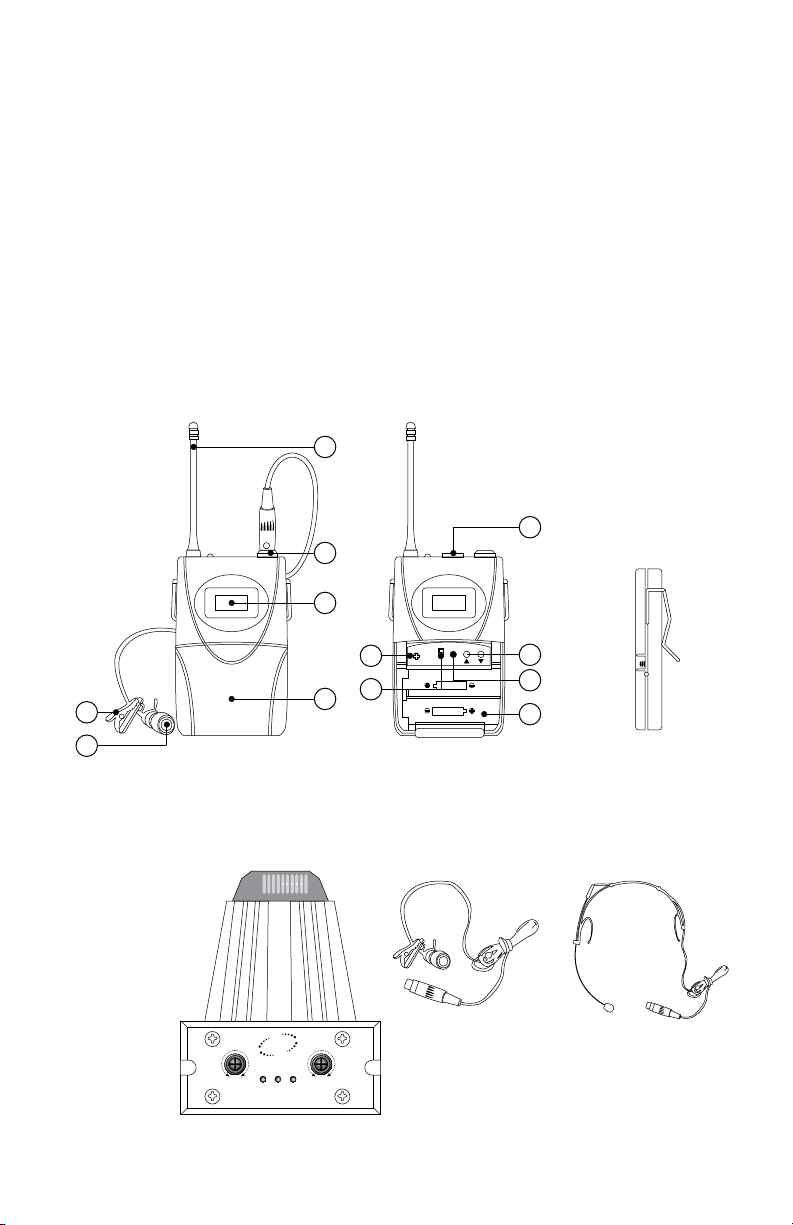
TIE-CLIP TRANSMITTER SPECIFICATION
(Optional Sale)
NAMES & FUNCTION:
Transmitter Body-pack System:
Outside Picture
1. Antenna
2. Microphone Jack
3. LCD
4. Battery Cover
5. Tie-Clip
6. Microphone Extension Jack
IDEA FOR YOUR CHOICE
1. 3.
2. 4.
TECHNICAL FEATURES
A. RECEIVER SPECIFICATION:
1. Sensitivity: 2uV (sinad=12dB)
2. Spurious rejection: ≥ 80dB
3. Image rejection: ≥ 80dB
4. SNR: ≥ 90dB
5. AF output: 0~300 mV
6. Receiving build-in channel: 4 channels
7. Power: DC13V~18V
8. Power consumption: 6W
9. Receiver Dimensions (WxHxD): 16x1.75x7.75(inches) / 40.64x4.45x19.7(cm)
10. Receiver Net Weight: 6.4 lbs / 2.9 kg
11. Shipping Weight: 11.6 lbs / 5.3 kg
B. HANDHELD TRANSMITTER SPECIFICATION:
1. Carrier Frequency: UHF730~820MHz
2. Frequency stability: ≤0.002%
3. RF power output: 30mW
4. Current loss: ≤100mA
5. Use range: 60m (ideal)
6. Pickup: Dynamic or condenser
7. Battery: 9Vx4
8. Power life: 8~10 hours
9. Handheld Transmitter Dimensions (WxH): 1.97x9.84 (inches) / 5x25 (cm)
10. Handheld Transmitter Net Weight: 0.6 lbs / 0.3 kg
UHF-SERIES
6
1
2
3
4
5
Optional
UHF-SERIES
SETGAIN
HI
POWER
LO
1
3
4
2
6
5
Optional
SQ
UHF WIRELESS RECEIVER MODULE
UHF
POWER RF AF
MIN MAX
Optional
Headset Mic.
(Accessories)
Optional
Optional
Lavalier Mic.
(Accessories)
Optional
Portable Channel Receiver
Optional: You may use
any Channel for
micphone, bodypack,
headset or lavalier
mic by replacing the
Portable Channel
Receiver. See
page 9 for
more details.
Inside Picture
1. Power Switch
2. Channel Selection
3. Setting
4. Battery Slot
5. Volume Control
6. Transmitter Power Switch on/off
Side-face
Picture
UHF-SERIES
BATLOW
ON
OFF
BATLOW
ON
OFF
BATLOW
ON
OFF
UHF-SERIES UHF-SERIES UHF-SERIES
UHF-SERIESUHF-SERIES UHF-SERIES UHF-SERIES
BATLOW
ON
OFF
UHF-SERIES UHF-SERIES
BATLOW
ON
OFF
BATLOW
ON
OFF

10 11
TIE-CLIP TRANSMITTER SPECIFICATION
(Optional Sale)
NAMES & FUNCTION:
Transmitter Body-pack System:
Outside Picture
1. Antenna
2. Microphone Jack
3. LCD
4. Battery Cover
5. Tie-Clip
6. Microphone Extension Jack
IDEA FOR YOUR CHOICE
1. 3.
2. 4.
TECHNICAL FEATURES
A. RECEIVER SPECIFICATION:
1. Sensitivity: 2uV (sinad=12dB)
2. Spurious rejection: ≥ 80dB
3. Image rejection: ≥ 80dB
4. SNR: ≥ 90dB
5. AF output: 0~300 mV
6. Receiving build-in channel: 4 channels
7. Power: DC13V~18V
8. Power consumption: 6W
9. Receiver Dimensions (WxHxD): 16x1.75x7.75(inches) / 40.64x4.45x19.7(cm)
10. Receiver Net Weight: 6.4 lbs / 2.9 kg
11. Shipping Weight: 11.6 lbs / 5.3 kg
B. HANDHELD TRANSMITTER SPECIFICATION:
1. Carrier Frequency: UHF730~820MHz
2. Frequency stability: ≤0.002%
3. RF power output: 30mW
4. Current loss: ≤100mA
5. Use range: 60m (ideal)
6. Pickup: Dynamic or condenser
7. Battery: 9Vx4
8. Power life: 8~10 hours
9. Handheld Transmitter Dimensions (WxH): 1.97x9.84 (inches) / 5x25 (cm)
10. Handheld Transmitter Net Weight: 0.6 lbs / 0.3 kg
UHF-SERIES
6
1
2
3
4
5
Optional
UHF-SERIES
SETGAIN
HI
POWER
LO
1
3
4
2
6
5
Optional
SQ
UHF WIRELESS RECEIVER MODULE
UHF
POWER RF AF
MIN MAX
Optional
Headset Mic.
(Accessories)
Optional
Optional
Lavalier Mic.
(Accessories)
Optional
Portable Channel Receiver
Optional: You may use
any Channel for
micphone, bodypack,
headset or lavalier
mic by replacing the
Portable Channel
Receiver. See
page 9 for
more details.
Inside Picture
1. Power Switch
2. Channel Selection
3. Setting
4. Battery Slot
5. Volume Control
6. Transmitter Power Switch on/off
Side-face
Picture
UHF-SERIES
BATLOW
ON
OFF
BATLOW
ON
OFF
BATLOW
ON
OFF
UHF-SERIES UHF-SERIES UHF-SERIES
UHF-SERIESUHF-SERIES UHF-SERIES UHF-SERIES
BATLOW
ON
OFF
UHF-SERIES UHF-SERIES
BATLOW
ON
OFF
BATLOW
ON
OFF
12 13
Band C
Band C Scan Group 1 Band C Scan Group 2 Band C Scan Group 3
TV Ch. Frequency – MHz * TV Ch. Frequency – MHz * TV Ch. Frequency – MHz *
25 (None) 0 25 541.500 1 25 541.500 1
26 542.750 26 542.750 26 542.125
26 545.500 26 544.375 26 543.500
26 547.125 26 544.750 26 544.000
26 547.375 4 26 545.750 26 546.250 4
27 549.750 26 547.500 5 27 548.250
27 550.375 27 (None) 0 27 549.750 2
27 550.625 3 28 554.250 28 555.750
28 557.250 28 556.125 28 556.625
28 557.500 28 557.500 28 558.250
28 559.250 28 559.375 4 28 559.375 4
28 559.500 4 29 560.000 29 560.125
29 562.000 29 561.875 29 561.500
29 563.375 29 562.250 29 564.000
29 563.625 3 29 563.250 29 564.250 4
30 566.000 29 565.500 5 30 566.125 1
30 566.250 2 30 566.000 1
Band D
Band D Scan Group 1 Band D Scan Group 2 Band D Scan Group 3
TV Ch. Frequency – MHz * TV Ch. Frequency – MHz * TV Ch. Frequency – MHz *
44 655.500 1 44 655.875 1 44 655.500
45 658.000 45 656.250 44 655.750 2
45 658.375 45 658.500 45 656.625
45 659.250 45 659.750 45 658.500
45 659.500 45 660.000 45 658.750
45 661.500 5 45 660.500 5 45 659.500 4
46 662.375 46 664.375 46 662.750
46 662.750 2 46 665.500 2 46 665.250 2
47 669.625 47 671.625 47 671.250
47 671.750 2 47 672.000 2 47 672.375
48 674.750 48 674.000 47 673.125 3
48 675.750 48 674.500 48 674.125
48 676.125 48 675.750 48 674.500
48 678.000 48 676.750 48 675.375
48 678.250 48 678.250 5 48 678.625
48 679.500 6 49 680.250 1 48 679.125 5
49 (None) 0 49 (None) 0
* Number of wireless frequencies in TV Channel.
FREQUENCY SCAN GROUPS FOR BAND C & BAND D
TV Ch.
Available
Frequency
01 733.78 MHz
02 743.30 MHz
03 747.10 MHz
04 756.72 MHz
05 763.38 MHz
06 738.59 MHz
07 759.68 MHz
08 766.71 MHz
09 774.11 MHz
10 796.68 MHz
11 796.68 MHz
12 802.60 MHz
13 762.50 MHz
14 743.03 MHz
15 747.10 MHz
16 763.38 MHz
17 762.50 MHz
LX-4040U FREQUENCY CHANNEL SYSTEM
PRECAUTION
1. The input power voltage of the receiver is 120V (±10%). If it is too low or too
high, it will effect the work of the machine.
2. When you install the battery, you must not reverse the electrode or you will
damage the machine.
3. When using the sensitivity solution function, the numerical value you select
must be at least 15dB. Otherwise, if the distance is too far, its signal-to noise
radio goes worse.
Caution: To reduce the risk of electrical
shock, do not remove the cover (or back).
No user serviceable parts inside: refer
servicing to qualified personnel.
Warning: To reduce the risk of fire or
electrical shock, do not expose this appliance
to rain or moisture.
RISK OF ELECTRIC SHOCK
DO NOT OPEN
14 15
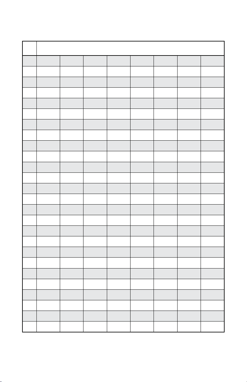
Band C: 541.500 - 566.375 MHz
TV Ch. Band D: 655.500 - 680.375 MHz
TV Ch.
44 --- --- --- --- 655.500 655.625 655.750 655.875
45 656.000 656.125 656.250 656.375 656.500 656.625 656.750 656.875
45 657.000 657.125 657.250 657.375 657.500 657.625 657.750 657.875
45 658.000 658.125 658.250 658.375 658.500 658.625 658.750 658.875
45 659.000 659.125 659.250 659.375 659.500 659.625 659.750 659.875
45 660.000 660.125 660.250 660.375 660.500 660.625 660.750 660.875
45 661.000 661.125 661.250 661.375 661.500 661.625 661.750 661.875
46 662.000 662.125 662.250 662.375 662.500 662.625 662.750 662.875
46 663.000 663.125 663.250 663.375 663.500 663.625 663.750 663.875
46 664.000 664.125 664.250 664.375 664.500 664.625 664.750 664.875
46 665.000 665.125 665.250 665.375 665.500 665.625 665.750 665.875
46 666.000 666.125 666.250 666.375 666.500 666.625 666.750 666.875
46 667.000 667.125 667.250 667.375 667.500 667.625 667.750 667.875
47 668.000 668.125 668.250 668.375 668.500 668.625 668.750 668.875
47 669.000 669.125 669.250 669.375 669.500 669.625 669.750 669.875
47 670.000 670.125 670.250 670.375 670.500 670.625 670.750 670.875
47 671.000 671.125 671.250 671.375 671.500 671.625 671.750 671.875
47 672.000 672.125 672.250 672.375 672.500 672.625 672.750 672.875
47 673.000 673.125 673.250 673.375 673.500 673.625 673.750 673.875
48 674.000 674.125 674.250 674.375 674.500 674.625 674.750 674.875
48 675.000 675.125 675.250 675.375 675.500 675.625 675.750 675.875
48 676.000 676.125 676.250 676.375 676.500 676.625 676.750 676.875
48 677.000 677.125 677.250 677.375 677.500 677.625 677.750 677.875
48 678.000 678.125 678.250 678.375 678.500 678.625 678.750 678.875
48 679.000 679.125 679.250 679.375 679.500 679.625 679.750 679.875
49 680.000 680.125 680.250 680.375 --- --- --- ---
25 --- --- --- --- 541.500 541.625 541.750 541.875
26 542.000 542.125 542.250 542.375 542.500 542.625 542.750 542.875
26 543.000 543.125 543.250 543.375 543.500 543.625 543.750 543.875
26 544.000 544.125 544.250 544.375 544.500 544.625 544.750 544.875
26 545.000 545.125 545.250 545.375 545.500 545.625 545.750 545.875
26 546.000 546.125 546.250 546.375 546.500 546.625 546.750 546.875
26 547.000 547.125 547.250 547.375 547.500 547.625 547.750 547.875
27 548.000 548.125 548.250 548.375 548.500 548.625 548.750 548.875
27 549.000 549.125 549.250 549.375 549.500 549.625 549.750 549.875
27 550.000 550.125 550.250 550.375 550.500 550.625 550.750 550.875
27 551.000 551.125 551.250 551.375 551.500 551.625 551.750 551.875
27 552.000 552.125 552.250 552.375 552.500 552.625 552.750 552.875
27 553.000 553.125 553.250 553.375 553.500 553.625 553.750 553.875
28 554.000 554.125 554.250 554.375 554.500 554.625 554.750 554.875
28 555.000 555.125 555.250 555.375 555.500 555.625 555.750 555.875
28 556.000 556.125 556.250 556.375 556.500 556.625 556.750 556.875
28 557.000 557.125 557.250 557.375 557.500 557.625 557.750 557.875
28 558.000 558.125 558.250 558.375 558.500 558.625 558.750 558.875
28 559.000 559.125 559.250 559.375 559.500 559.625 559.750 559.875
29 560.000 560.125 560.250 560.375 560.500 560.625 560.750 560.875
29 561.000 561.125 561.250 561.375 561.500 561.625 561.750 561.875
29 562.000 562.125 562.250 562.375 562.500 562.62 5562.750 562.875
29 563.000 563.125 563.250 563.375 563.500 563.625 563.750 563.875
29 564.000 564.125 564.250 564.375 564.500 564.625 564.750 564.875
29 565.000 565.125 565.250 565.375 565.500 565.625 565.750 565.875
30 566.000 566.125 566.250 566.375 --- --- --- ---
US UHF WIRELESS OPERATING FREQUENCIES
Avoid using same frequencies as TV channels or other radio signals for better performance. Avoid using same frequencies as TV channels or other radio signals for better performance.

14 15
Band C: 541.500 - 566.375 MHz
TV Ch. Band D: 655.500 - 680.375 MHz
TV Ch.
44 --- --- --- --- 655.500 655.625 655.750 655.875
45 656.000 656.125 656.250 656.375 656.500 656.625 656.750 656.875
45 657.000 657.125 657.250 657.375 657.500 657.625 657.750 657.875
45 658.000 658.125 658.250 658.375 658.500 658.625 658.750 658.875
45 659.000 659.125 659.250 659.375 659.500 659.625 659.750 659.875
45 660.000 660.125 660.250 660.375 660.500 660.625 660.750 660.875
45 661.000 661.125 661.250 661.375 661.500 661.625 661.750 661.875
46 662.000 662.125 662.250 662.375 662.500 662.625 662.750 662.875
46 663.000 663.125 663.250 663.375 663.500 663.625 663.750 663.875
46 664.000 664.125 664.250 664.375 664.500 664.625 664.750 664.875
46 665.000 665.125 665.250 665.375 665.500 665.625 665.750 665.875
46 666.000 666.125 666.250 666.375 666.500 666.625 666.750 666.875
46 667.000 667.125 667.250 667.375 667.500 667.625 667.750 667.875
47 668.000 668.125 668.250 668.375 668.500 668.625 668.750 668.875
47 669.000 669.125 669.250 669.375 669.500 669.625 669.750 669.875
47 670.000 670.125 670.250 670.375 670.500 670.625 670.750 670.875
47 671.000 671.125 671.250 671.375 671.500 671.625 671.750 671.875
47 672.000 672.125 672.250 672.375 672.500 672.625 672.750 672.875
47 673.000 673.125 673.250 673.375 673.500 673.625 673.750 673.875
48 674.000 674.125 674.250 674.375 674.500 674.625 674.750 674.875
48 675.000 675.125 675.250 675.375 675.500 675.625 675.750 675.875
48 676.000 676.125 676.250 676.375 676.500 676.625 676.750 676.875
48 677.000 677.125 677.250 677.375 677.500 677.625 677.750 677.875
48 678.000 678.125 678.250 678.375 678.500 678.625 678.750 678.875
48 679.000 679.125 679.250 679.375 679.500 679.625 679.750 679.875
49 680.000 680.125 680.250 680.375 --- --- --- ---
25 --- --- --- --- 541.500 541.625 541.750 541.875
26 542.000 542.125 542.250 542.375 542.500 542.625 542.750 542.875
26 543.000 543.125 543.250 543.375 543.500 543.625 543.750 543.875
26 544.000 544.125 544.250 544.375 544.500 544.625 544.750 544.875
26 545.000 545.125 545.250 545.375 545.500 545.625 545.750 545.875
26 546.000 546.125 546.250 546.375 546.500 546.625 546.750 546.875
26 547.000 547.125 547.250 547.375 547.500 547.625 547.750 547.875
27 548.000 548.125 548.250 548.375 548.500 548.625 548.750 548.875
27 549.000 549.125 549.250 549.375 549.500 549.625 549.750 549.875
27 550.000 550.125 550.250 550.375 550.500 550.625 550.750 550.875
27 551.000 551.125 551.250 551.375 551.500 551.625 551.750 551.875
27 552.000 552.125 552.250 552.375 552.500 552.625 552.750 552.875
27 553.000 553.125 553.250 553.375 553.500 553.625 553.750 553.875
28 554.000 554.125 554.250 554.375 554.500 554.625 554.750 554.875
28 555.000 555.125 555.250 555.375 555.500 555.625 555.750 555.875
28 556.000 556.125 556.250 556.375 556.500 556.625 556.750 556.875
28 557.000 557.125 557.250 557.375 557.500 557.625 557.750 557.875
28 558.000 558.125 558.250 558.375 558.500 558.625 558.750 558.875
28 559.000 559.125 559.250 559.375 559.500 559.625 559.750 559.875
29 560.000 560.125 560.250 560.375 560.500 560.625 560.750 560.875
29 561.000 561.125 561.250 561.375 561.500 561.625 561.750 561.875
29 562.000 562.125 562.250 562.375 562.500 562.62 5562.750 562.875
29 563.000 563.125 563.250 563.375 563.500 563.625 563.750 563.875
29 564.000 564.125 564.250 564.375 564.500 564.625 564.750 564.875
29 565.000 565.125 565.250 565.375 565.500 565.625 565.750 565.875
30 566.000 566.125 566.250 566.375 --- --- --- ---
US UHF WIRELESS OPERATING FREQUENCIES
Avoid using same frequencies as TV channels or other radio signals for better performance. Avoid using same frequencies as TV channels or other radio signals for better performance.

Printed on 100% Recycled Paper
Comments to
29300 Kohoutek Way #150
Union City, CA 94587 U.S.A.
E-mail: [email protected]
Website: www.nissindousa.com
Nissindo Trademark All Rights Reserved.
Design and Engineered in U.S.A. MFD Code: Y060222-ID
Thank you for purchasing this unit. To make full
and effective use of this unit, please read this
Owner's Manual carefully before operating it.
After reading, retain this booklet together with
the Warranty Card for future use in case of
defections or other troubles.
Table of contents
Other Nissindo Microphone System manuals


Popular Microphone System manuals by other brands


Atlas
Atlas AL2430-2PH owner's manual

RELACART
RELACART ER-5700 Additional Instructions for Installation and Operation

Speaka Professional
Speaka Professional SP-6773664 operating instructions

Opus Technologies
Opus Technologies OP-8TH Installation and user manual

Chiayo
Chiayo IRX2 Operation manual

PRYME
PRYME MIRAGE SPM-1399 Series quick start guide


