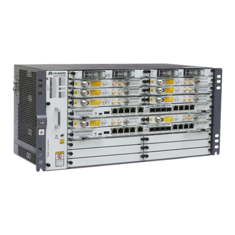
Huawei OptiX RTN 905 User manual

HUAWEI TECHNOLOGIES CO., LTD.
OptiX RTN 905 Radio Transmission System V100
Quick Installation Guide
for Outdoor Cabinets (OMB Cabinets)
Issue: 01
Date:2018-10-30

Huawei Technologies Co., Ltd.
Address: Huawei Industrial Base
Bantian, Longgang
Shenzhen 518129
People's Republic of China
Website: http://www.huawei.com
Email: support@huawei.com
No part of this document may be reproduced or transmitted in any form or by any means without prior
written consent of Huawei Technologies Co., Ltd.
Copyright © HuaweiTechnologiesCo.,Ltd. 2018. All rights reserved.
Trademarksand Permissions
and other Huawei trademarks are trademarks of Huawei Technologies Co., Ltd.
All other trademarks and trade names mentioned in this document are the property of their respective
holders.
Notice
The purchased products, services and features are stipulated by the contract made between Huawei and
the customer. All or part of the products, services and features described in this document may not be
within the purchase scope or the usage scope. Unless otherwise specified in the contract, all statements,
information, and recommendations in this document are provided "AS IS" without warranties, guarantees
or representations of any kind, either express or implied.
The information in this document is subject to change without notice. Every effort has been made in the
preparation of this document to ensure accuracy of the contents, but all statements, information, and
recommendations in this document do not constitute a warranty of any kind, express or implied.

1
Precautions
Following All Safety Precautions
Before anyoperation,readthe instructions andprecautionsinthis documentcarefullyto minimizethe possibility
of accidents.
The Danger,Caution,andNote items inthe documents donotcover allthe safety precautions thatmustbe
followed.They onlyprovide the genericsafetyprecautions foroperations.
When operatingHuaweiproducts and equipment,you mustcomplywith safetyprecautions and specialsafety
instructions relatedtocorrespondingequipmentprovidedbyHuawei.The safetyprecautions inthedocumentare
relatedto only Huaweiproducts.Huaweiis notliableforanyconsequencethatresults from the violationof
universalregulationsforsafetyoperations andsafetycodes on design,production,and equipmentuse.
Complying with the Local SafetyRegulations
When operatingthe productor equipment,complywithlocalsafetyregulations.
Qualified Personnel Only
Installationandmaintenancepersonnelmustbetrainedtoperform operations correctlyand safely.
Personnel Safety
The high-voltagepowersupplyprovides powerfor running thesystem.Avoid direct contact withthe high-voltage
powersupplyor contact through damp objects.Failure todo so causes seriousinjuryordeath.
Non-standardandincorrectoperationsonthehigh-voltagepowersupplymayresultin fire andelectricshock.
Do not perform operations on high-voltageandACpowersupplyfacilities oron a tower or mastin the caseof
thunderstorm.Failuretodosocauses serious injuryor death.
Groundthe device before powering iton. Failure to do so causes damagetothe device or personal injury.
Poweroff the device beforeperforming operationsonthepowersupplyfacilities.
Personnel Safety
Highpowerradio-frequencysignalsareharmfultothe humanbody.Ensurethat the transmitterantennas are
muted before installing ormaintainingan antenna ona toweror mastthat holds a largenumberoftransmitter
antennas.
Do not standcloseto,or look intothe opticalfiber outlet withouteye protectionwhenhandling opticalfibers.
Take preventive measures whendrilling holes.Otherwise,dustmayhurt your eyes or you mayinhalethe dust.
When working at heights,be cautious aboutfallingobjects.
Device Safety
Checkthe electricalconnectionof the device before operationandensure thatthe device is securelygrounded.
The staticelectricity discharged from the human bodymaydamage theelectrostaticsensitive components,such
as large-scale integrated circuits(LSIs),on the circuitboard. Wear anESD wriststrapor ESD gloves when
handlingacircuitboard.
2
Tools for Installation
NetworkcabletesterCOAX stripper
Measuring tape Phillips screwdriver Flat-head screwdriver AdjustableWrenchLevel
COAX crimping tool
Socket wrench Torque wrench Hex key Wire clippers
Wire stripper RJ45 crimping tool Diagonal pliers Cold press pliers Needle-nose pliers
Combination pliersBayonetwrench
Utility knife Claw hammerHammer drill Marker
Ladder Soldering iron
ESD gloves
Heat gunMultimeter
ESD gloves
Binding strap Insulation tape
ESD wriststrap Impact tool
File
Vacuumcleaner

3
Introduction to the Equipment
1Introduction to the RTN 905
FrontViewof the RTN9051A
a
FrontViewof the RTN9052A
b
NMS/COM
EXT/S1
CLK/TOD/MON
ALMI/ALMO
GE1
GE2
GE3
GE4
GE5GE6 TDMA TDMB
OptiX RTN 905
1 A
STAT
SRV
PWRA
PWRB
L/A5
L/A6
USB
RTNB
(+)
NEGB
(-)
RTNA
(+)
NEGA
(-)
OUT IN OUT IN
-48V -60V
116
ESD
TURN OFF POWER BEFORE
WARNING
-48V OUTPUT
DISCONNECTING IF CABLE
!
LINK
ODU
10
11
12
13
NE cascading
port/Asynchronous
data port
10
11
External clock port/
external time port/ outdoor
cabinet monitoring port
NMS port/NMS serial
port
Ground screw
Port for the ESD
wrist strap
16xE1 ports
USB port
GE/FE service ports
(SFP modules)
TDM service
concatenation ports
IF port to the ODU
DC-C power socket
FE/GE service electrical
ports (RJ45 connectors)
12
13
Alarm
input/outputport
NMS/COM
EXT/S1
CLK/TOD/MON
ALMI/ALMO
GE1
GE2
GE3
GE4
GE5GE6 TDMA TDMB
OptiX RTN 905
2 A
STAT
SRV
PWRA
PWRB
L/A5
L/A6
USB
RTNB
(+)
NEGB
(-)
RTNA
(+)
NEGA
(-)
OUT IN OUT IN
-48V -60V
116
ESD
TURN OFF POWER BEFORE
WARNING
-48V OUTPUT
DISCONNECTING IF CABLE
!
OFF
ODU-1
ON
PULL
ODU-2
ON
PULL OFF ACT1
LINK2
ACT2
LINK1
10
11
12
13
14
USB port
10
11
NMS port/NMS
serial port
ODU power switch
Ground screw
16xE1 ports
TDM service
concatenation ports
IF port to the ODU
FE/GE service electrical
ports (RJ45 connectors)
GE/FE service ports (SFP
modules)
DC-C power socket
Port for the ESD
wrist strap
External clock port/
external time port/ outdoor
cabinet monitoring port
12
13
NE cascading
port/Asynchronous
data port
14
Alarm
input/outputport

4a
Introduction to the Equipment
FrontViewof the RTN9051C
c
Ground screw
DC-C power socket
(Caution! See "Precautions
for Handling Power
Cables.")
NE status indicator USB port
FE/GE service
electrical ports (RJ-45
connectors)
GE/FE serviceports
(SFP modules)
TDM service
concatenation ports
1
2
3
5
IF port to the ODU/
XPIC input/output
ports
6
Radio link status
indicator
7
8
Status indicators of
the GE/FE service
ports (SFP
modules)
9
USB port status
indicator
10
11
12
NMS port/NMS
serial port
NE cascading port/
Asynchronous data port
Clock port (CLK)/High-precision
time port (TOD)/Outdoor cabinet
monitoring port (MON)
16
17
16xE1 ports
4
Alarm input/output
port
13
14
15
1
2
3
4
5
6
7
8
9
10
11
13
16
12
14
15
17
19
18
18
Port for the ESD wrist
strap
19
STM-1 serv iceports
1+1 / TDM service
concatenation ports
FrontViewof the IDU 905 1E
d
Ground screw
DC-C power socket
(Caution! See "Precautions
for Handling Power
Cables.")
NE status indicator
1
2
3
1
2
3
4
5
6
7
8
9
10
11
13
16
12
14
15
17
19
18
Mini USB port
FE/GE service
electrical ports (RJ-45
connectors)
GE/FE serviceports
(SFP modules)
STM-1 serviceports
5
IF port to the ODU /
XPIC input/output
ports
6
Radio link status
indicator
7
8
Status indicators of
the GE/FE service
ports (SFP
modules)
9
USB port/Status
indicator
10
11
12
NMS port/NMS serial
port
NE cascading port/
Asynchronous data
port
Clock port (CLK)/High-precision
time port (TOD)/Outdoor cabinet
monitoring port (MON)
16
17
16xE1 ports
4
Alarm input/output
port
13
14
15
18
COMBO ports Port for the ESD wrist
strap
19
MN1 subboard

4b
Front View of the IDU 905 2E
e
Ground screw
DC-C power socket
(Caution! See "Precautions
for Handling Power
Cables.")
NE status indicator
1
2
3
1
2
3
4
5
6
7
8
9
10
11
13
16
12
14
15
17
19
18
Mini USB port
5
IF ports to the
ODU/ODU switches
6
Radio link status
indicator
7
8
Status indicators of
the GE/FE service
ports (SFP
modules)
9
USB port/Status
indicator
10
11
12
NMS port/NMS serial
port
NE cascading port/
Asynchronous data port
Clock port (CLK)/High-precision
time port (TOD)/Outdoor cabinet
monitoring port (MON)
4
Alarm input/output
port
Power over Ethernet
port
GE/FE serviceports
(SFP modules)
STM-1 serv iceports
16
17
16xE1 ports
13
14
15
18
COMBO ports
Port for the ESD wrist
strap
19
MN1 subboard
20
FE/GE service
electrical ports (RJ-45
connectors)
20

5
2Introduction to the OMB Cabinet
FrontViewof the OMBCabinet
a
Left Viewof the OMBCabinet
bRight Viewof the OMBCabinet
c
Technical Specifications
Dimensions(mm):600(H)x 240 (W) x 430(D)
Ambienttemperature(nosunshineradiation):-20℃to +50 ℃

6
About the InternalStructureof the OMBCabinet
d
Fan assembly(internalcirculating)
Internal Structure of the OMB Cabinet (AC Power Supply)
Internal Structure of the OMB Cabinet (DC Power Supply)
HEUA
OMB cabinet(AC powersupply)
Fan assembly(external circulating)
AC/DC powersupplyfacility
PMU module
Fan assembly(internalcirculating)
HEUA
OMB cabinet(DCpowersupply)
Fan assembly(external circulating)
DCDU-03B
Cabletrough
AC surgeprotectionbox

7
Installation Scenarios of the Cabinets
1Installation Scenarios of the OMB Cabinet
Recommended Requirementsof
the OMBCabinet
aMinimumRequirementsof the
OMBCabinet
b
≥200 mm
≥150 mm
≥600 mm
≥500 mm
≥200 mm
≥300 mm
≥800 mm
≥600 mm

8
InstallationModes
d
Installing the OMB cabinet on a pole Installing the OMB cabinet on a wall
The OMB cabinetprovides asmall space. Therefore,donot use theOMB cabinetin anarea where the
ambienttemperatureis lowerthan –20°Cinwinter.It is recommendedthatyou usethe APM30H or TMC11H
cabinetthat is configured witha heater.
2Installing the OMB Cabinet
Installingthe OMBCabinetona Wall
a
210mm
378mm
210mm
378mm
Determine the position ofthe backplaneon thewall, and
markthe four anchorpoints byusing amarker. Drillthe holes andinstall the expansionboltassembly.
55~60mm 90
φ14
3
45 6
20~30mm
。
Bolt M10x75
Spring w asher10
Plastic tube
Flat washer10
Expansion bolt
NOTE

9
Installthe backplaneofthe OMB frameonthe wall.
Installthe OMB frame on the backplane.
Installingthe OMBCabinetona Pole
b
Installthe firstupperfastenerassemblyonthe pole.
Flat washer
Spring washer
M10x180 bolt
Installthe lowerfastenerassemblyon the backplane.
M10x40 bolt
M6 screw

10
Installthe backplaneonthepole.
Installthe mountingbrackets forthe OMB frame.
Installthe OMB frameon the backplane.

11
Outdoor Pole-MountingScenario
1Dedicated Outdoor Installation
Installingthe RTN905in the OMBCabinet(AC PowerSupply)
a
Installingthe RTN905in the OMBCabinet(DCPowerSupply)
b
This installationscenarioappliestotheRTN 905.
NOTE
NOTE

12
Installing the Assemblies
1Installing the RTN 905
The RTN 905mustbeinstalledonthe left
sideof the surge-protectionbox(SLPU).
2Installing the SLPU
The SLPU mustbeinstalledon therightside
of the RTN 905
Groundterminal
When installing theRTN905,ensure that the
powermoduleofthe equipmentis downward.
The RTN 905can be installed inside
OMB cabinets inthe samemanner.
NOTE

13
1Installing the PGND Cables
Installingthe PGND Cablesforthe Cabinet
a
Cableinstallationis the same for
the RTN 905 installedinside DC
powered OMB cabinets.
When installing the PGND cables
in the DC poweredOMB cabinet,
usethe samemethodas thatin
the AC poweredOMB cabinet.
The ground cables and signal
cables mustbeboundseparately
or mustbeseparated from each
other for certainspacing to
minimizemutualinterference.
The PGND cables areinyellow-
green color. The general ground
cablehas a cross-sectionalarea
of 16 mm2.
Installingthe PGND Cablesforthe RTN905
b
Groundbar
NOTE
Installingand Routing the Cables

14
Installingthe InputPowerCablefor the OMBCabinet(AC Power Supply)
a
a
b
b
aN
PE
L
Installingthe InputPowerCablefor the RTN 905
b
2
NOTE
2
1
1
When installingpowercables fortheRTN 905, ensurethatthe power
cables are correctlyconnected to the positiveand negative terminals of
the powerdistributionbox.
2Installing and Routing the Power Cables –AC Power Supply
For AC OMB cabinets ofVer. C, connectthe two powercables from
RTN 905to anytwo poweroutput terminals (such as terminals LOAD6
and LOAD7) with the maximum outputcurrentof 30A. For information
aboutassemblingthe easypowerreceptacle (pressfittype) connector,
see"Appendixes ".

15
Installingthe InputPowerCablefor the OMBCabinet
a
Installingthe InputPowerCablefor the RTN 905
b
RTN(
+)
NEG(-)
Ensure that the input
powercables ofan OMB
cabinetare correctly
connectedto the positive
and negative terminals of
the powerdistributionbox.
1
2
1
When installingpowercables forthe RTN 905, ensurethatthe power
cables are correctlyconnected to the positiveand negative terminals of
the DC powerdistributionbox.
3Installing and Routing the Power Cables –DC Power Supply
For AC OMB cabinets ofVer. C, connectthe two powercables from
RTN 905to anytwo poweroutput terminals (suchas terminals LOAD6
andLOAD7) with the maximum outputcurrentof 30 A. For information
aboutassemblingthe easypowerreceptacle(pressfittype) connector,
see"Appendixes ".

16
INSIDE OUTSIDE
1~8
INSIDE OUTSIDE
4Installing the Service Cables for the Equipment –AC Power
Supply
InstallingE1 Cables
a
InstallingEthernetCables
b
Rubberblock
FE0
OUTSIDE
UFLP
INSIDE
FE1 FE0 FE1
FE0
OUTSIDE
UFLP
INSIDE
FE1FE0FE1
Rubberblock
E1 cables for1xAnea
96/4xDB25 conversion
are used.

17
InstallingIF Cables
c
InstallingFibers
d
Rubberblock
Insulationtube
Binding strap
Table of contents
Other Huawei Microphone System manuals

Huawei
Huawei OptiX RTN 980 User manual

Huawei
Huawei OptiX RTN 980L V100 User manual

Huawei
Huawei OptiX RTN 980 User manual

Huawei
Huawei RTN 360 V100 User manual

Huawei
Huawei OptiX RTN 320F User manual

Huawei
Huawei OptiX OSN 550 User manual

Huawei
Huawei OptiX RTN 600 Technical specifications

Huawei
Huawei RTN XMC ODU Technical specifications

Huawei
Huawei OptiX RTN 950 User manual

Huawei
Huawei OptiX OSN 2500 User manual