Nissindo LX-8080 Owner's manual
POWER ANTENA-A CNANNEL-A DISPLAY CNANNEL-B DISPLAY
CHANNEL-A
VOLUME ANTENA-B
CHANNEL-B
VOLUME
GETTO THE POINT
LX-8080
DUAL CHANNEL VHF WIRELESS SYSTEM
RF
AF
FREQ.
5 10 15 20 25 30 35 40
-30 -25 -20 -15 -10 -5 0 PEAK
000.000M
H
Z
MUTE
RF
AF
FREQ.
5 10 15 20 25 30 35 40
-30 -25 -20 -15 -10 -5 0 PEAK
000.000M
H
Z
MUTE
GETTOTHE POINT
GETTOTHE POINT
CHARGER 21
BATT LOW
ON
OFF
BATT LOW
ON
OFF
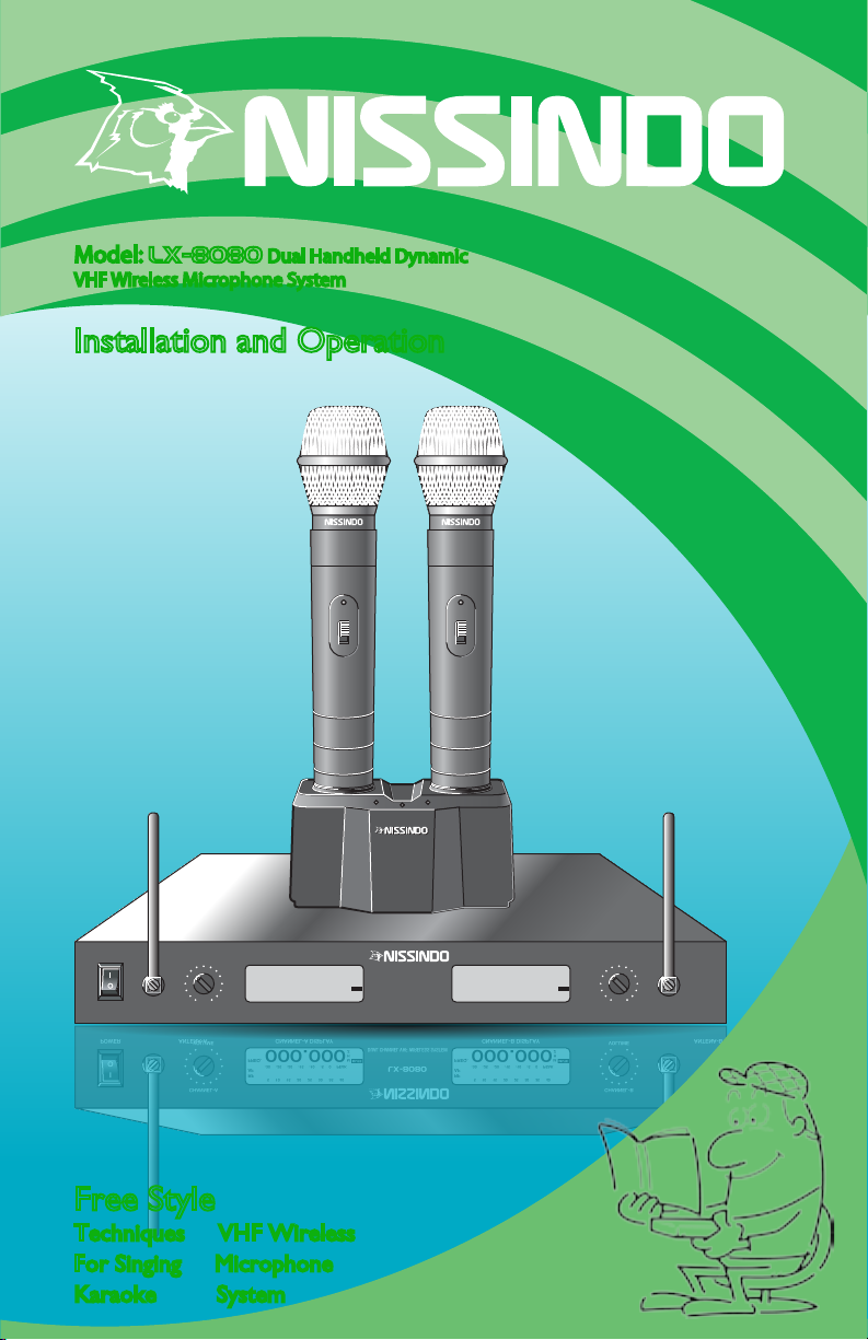
Model: LX-8080 Dual Handheld Dynamic
VHF Wireless Microphone System
Installation and Operation
Free Style
Techniques VHF Wireless
For Singing Microphone
Karaoke System
Model: LX-8080 Dual Handheld Dynamic
VHF Wireless Microphone System
Installation and Operation
Free Style
Techniques VHF Wireless
For Singing Microphone
Karaoke System
Comments? [email protected]
Nissindo Trademark All Right Reserved.
Engineered And Design In U.S.A.
Model: Lx-8080
Serial:
Frequency: A MHz
Frequency: B MHz BALANCEDUNBALANCED UNBALANCED
OUTPUT
CHANNEL B
MIXED A & B
CHANNEL OUTPUT DC-POWER
SQ
DC 17V 600mA
UNBALANCEDBALANCED
OUTPUT
CHANNEL A
RISK OF ELECTRIC SHOCK
DO NOT OPEN
Taking apart or modifying the receiver
may lead to electric shock, fire, or
damage to the receiver and will void
your warranty.
BATT LOW
ON
OFF
POWER ANTENA-A CNANNEL-A DISPLAY CNANNEL-B DISPLAY
CHANNEL-A
VOLUME ANTENA-B
CHANNEL-B
VOLUME
GETTO THE POINT
LX-8080
DUAL CHANNEL VHF WIRELESS SYSTEM
RF
AF
FREQ.
5 10 15 20 25 30 35 40
-30 -25 -20 -15 -10 -5 0 PEAK
000.000M
H
Z
MUTE
RF
AF
FREQ.
5 10 15 20 25 30 35 40
-30 -25 -20 -15 -10 -5 0 PEAK
000.000M
H
Z
MUTE
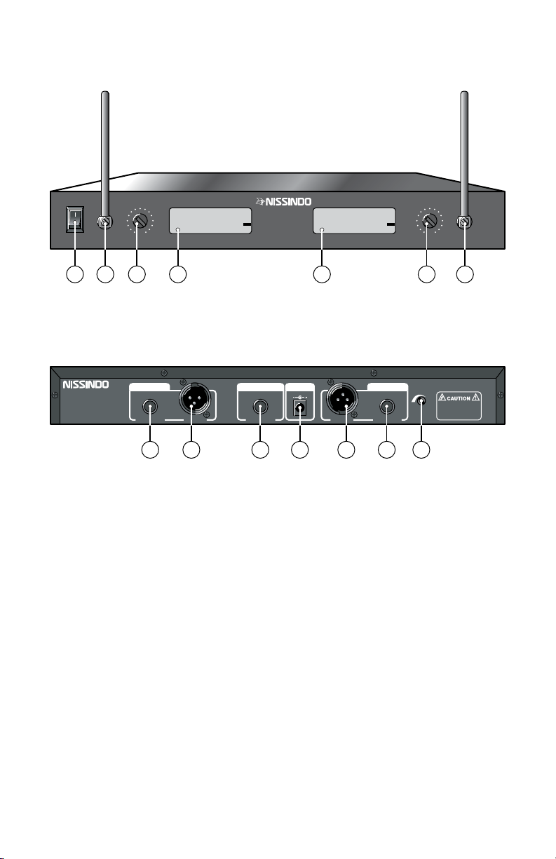
LX-8080 Receiver Features and Controls (Figure 1)
Rear view
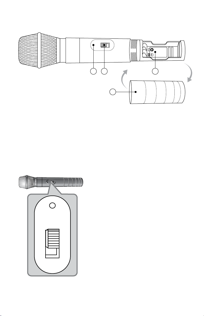
Lx-8080 Transmitter Features and Controls (Figure 3)
LX-8080 Handheld Transmitter (Figure 2)
1. Power switch On/Off.
2. Reveicer Antenas-A.
3. Channel-A AF volume adjust output jacks +/-15KHz.
4. LED Display (Channel-A).
5. LED Display (Channel-B).
6. Channel-B AF volume adjust output jacks +/-15KHz.
7. Reveicer Antenas-B.
8. Channel-B 1/4-inch unbalance audio output connector.
9. Channel-B XLR balance audio output 50Hz~15KHz +/-3dB.
10. Mixed channels 1/4-inch unbalance audio output 50Hz~15KHz +/-3dB.
11. Docking power supply with removable IEC cable 12.5-17.0 V 600mA.
12. Channel-A XLR balance audio output 50Hz~15KHz +/-3dB.
13. Channel-A 1/4-inch unbalance audio output connector.
14. Adjusts squelch control setting to emphasize either signal quality.
2 3
15. Indicates low battery.
16. Easily-accessible power switch On/Off.
17. Battery cover unscrews for access to the 9V battery rechargeable.
18. Variable battery cover.
Battery condition Indicator: After battery is
installed, turn the power on. The battery
condition indicator signal light should flash
once. If it does not, the battery is installed
incorrectly or it is dead. If the indicator signal
light stays on (does not flash), the battery
voltage is low and the battery should be
replaced. If this happens during use, replace
(or recharge) the battery immediately to
ensure continued operation.
Transmitter power switch (On/Off)
18
15
Top view
1
8 9 10 12 13 1411
2 3 6 74 5
BATT LOW
ON
OFF
9V
16 17
BATT LOW
ON
OFF
Comments? [email protected]
Nissindo Trademark All Right Reserved.
Engineered And Design In U.S.A.
Model: Lx-8080
Serial:
Frequency: A MHz
Frequency: B MHz BALANCEDUNBALANCED UNBALANCED
OUTPUT
CHANNEL B
MIXED A & B
CHANNEL OUTPUT DC-POWER
SQ
DC 17V 600mA
UNBALANCEDBALANCED
OUTPUT
CHANNEL A
RISK OF ELECTRIC SHOCK
DO NOT OPEN
Taking apart or modifying the receiver
may lead to electric shock, fire, or
damage to the receiver and will void
your warranty.
BATT LOW
ON
OFF
POWER ANTENA-A CNANNEL-A DISPLAY CNANNEL-B DISPLAY
CHANNEL-A
VOLUME ANTENA-B
CHANNEL-B
VOLUME
GETTO THE POINT
LX-8080
DUAL CHANNEL VHF WIRELESS SYSTEM
RF
AF
FREQ.
5 10 15 20 25 30 35 40
-30 -25 -20 -15 -10 -5 0 PEAK
000.000M
H
Z
MUTE
RF
AF
FREQ.
5 10 15 20 25 30 35 40
-30 -25 -20 -15 -10 -5 0 PEAK
000.000M
H
Z
MUTE
LX-8080 Receiver Features and Controls (Figure 1)
Rear view
Lx-8080 Transmitter Features and Controls (Figure 3)
LX-8080 Handheld Transmitter (Figure 2)
1. Power switch On/Off.
2. Reveicer Antenas-A.
3. Channel-A AF volume adjust output jacks +/-15KHz.
4. LED Display (Channel-A).
5. LED Display (Channel-B).
6. Channel-B AF volume adjust output jacks +/-15KHz.
7. Reveicer Antenas-B.
8. Channel-B 1/4-inch unbalance audio output connector.
9. Channel-B XLR balance audio output 50Hz~15KHz +/-3dB.
10. Mixed channels 1/4-inch unbalance audio output 50Hz~15KHz +/-3dB.
11. Docking power supply with removable IEC cable 12.5-17.0 V 600mA.
12. Channel-A XLR balance audio output 50Hz~15KHz +/-3dB.
13. Channel-A 1/4-inch unbalance audio output connector.
14. Adjusts squelch control setting to emphasize either signal quality.
2 3
15. Indicates low battery.
16. Easily-accessible power switch On/Off.
17. Battery cover unscrews for access to the 9V battery rechargeable.
18. Variable battery cover.
Battery condition Indicator: After battery is
installed, turn the power on. The battery
condition indicator signal light should flash
once. If it does not, the battery is installed
incorrectly or it is dead. If the indicator signal
light stays on (does not flash), the battery
voltage is low and the battery should be
replaced. If this happens during use, replace
(or recharge) the battery immediately to
ensure continued operation.
Transmitter power switch (On/Off)
18
15
Top view
1
8 9 10 12 13 1411
2 3 6 74 5
BATT LOW
ON
OFF
9V
16 17
BATT LOW
ON
OFF
Nissindo Trademark All Right Reserved.
Engineered And Design In U.S.A.
Model: Lx-8080
Serial:
Frequency: A MHz
Frequency: B MHz BALANCEDUNBALANCED UNBALANCED
OUTPUT
CHANNEL B
MIXED A & B
CHANNEL OUTPUT DC-POWER
SQ
DC 17V 600mA
UNBALANCEDBALANCED
OUTPUT
CHANNEL A
RISK OF ELECTRIC SHOCK
DO NOT OPEN
Taking apart or modifying the receiver
may lead to electric shock, fire, or
damage to the receiver and will void
your warranty.
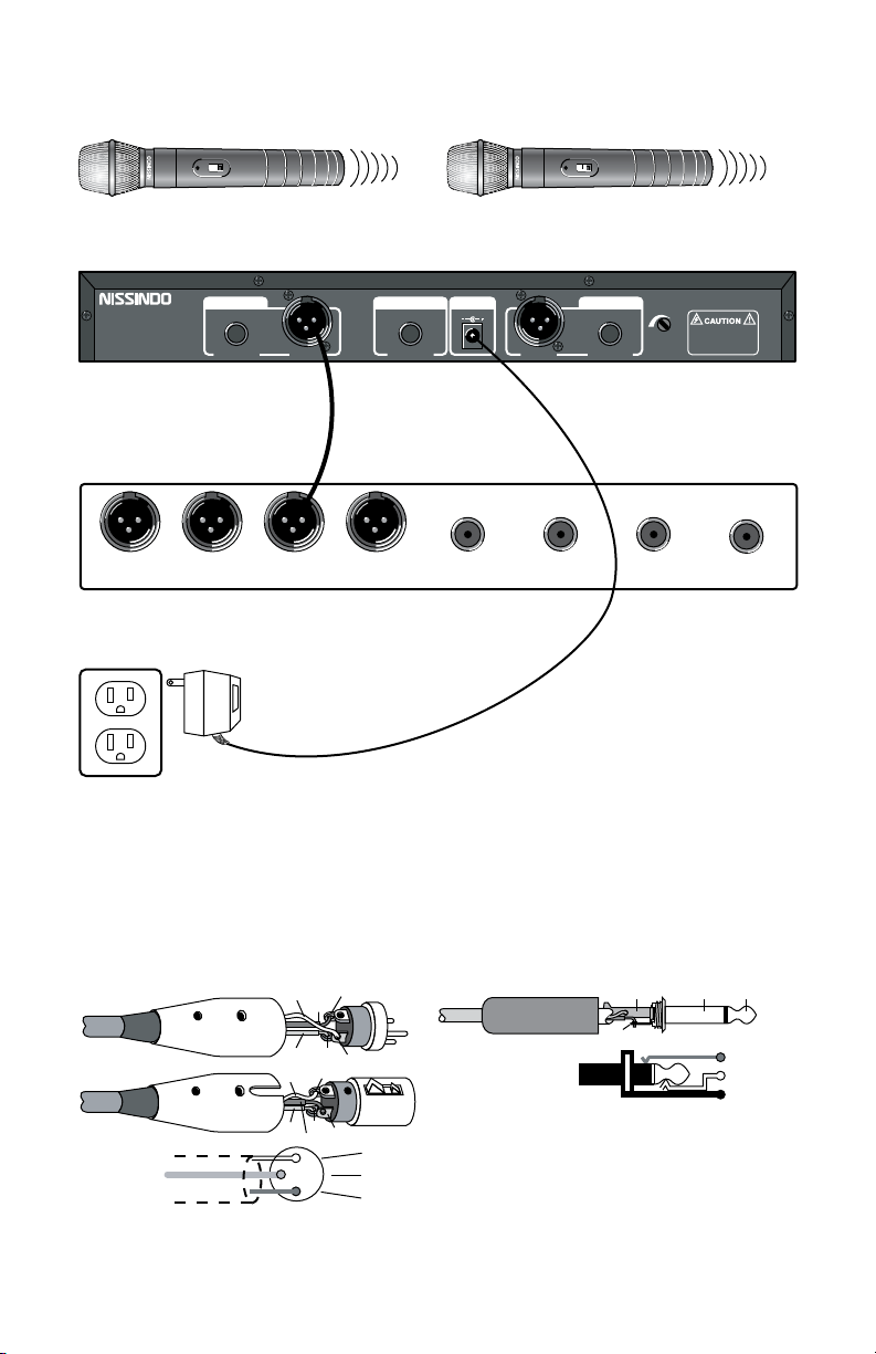
Handheld Transmitter Channel A & B (Figure 4) LX-8080 VHF Wireless System Chart (Figure 7)
Audio Cable Balance
(Figure 8)
Audio Cable Unbalance
(Figure 9)
Channel A Handheld Transmitter
Audio Mixer Amplifier or a Karaoke Unit Input terminal
Rear View
120V AC DC-17V 600mA adaptor
4 5
Make sure that you insert the battery at the
right electric poles.
XLR
Balance Input
XLR
Balance Input
XLR
Balance Input
XLR
Balance Input
1/4"
Unbalance Input
1/4"
Unbalance Input
1/4"
Unbalance Input 1/4"
Unbalance Input
9 V
ALKALINE
BATTERY
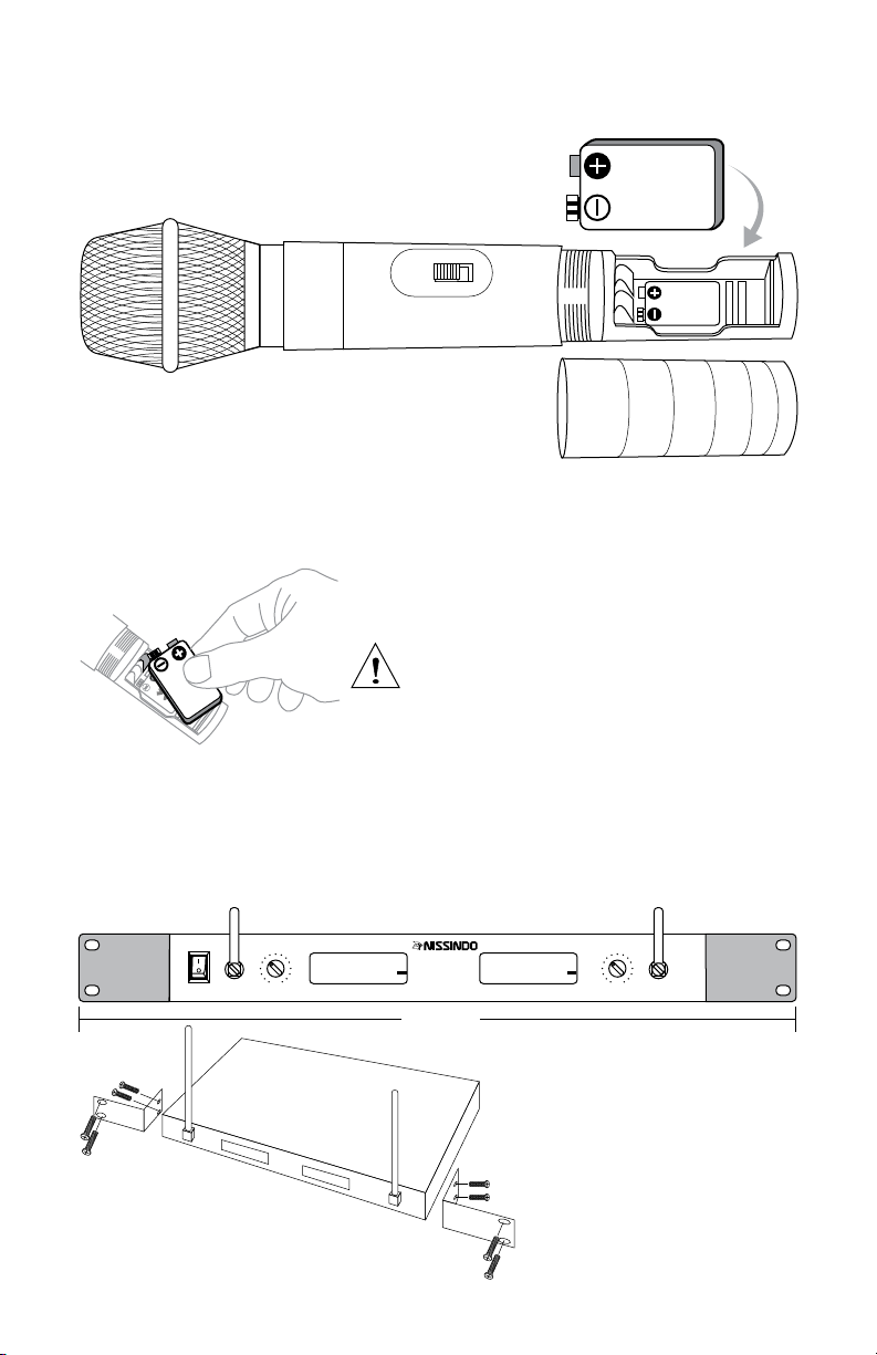
How to install battery to transmitter? (Figure 5)
How to install the mount to the rack for receiver?
(Figure 6)
Make sure that you insert the
battery at the right electric poles.
RING (COLD)
TIP (HOT)
SLEEVE (SHIELD)
SLEEVESLEEVE TIP
TIP
1SHID
COLD
HOT
2
3
1
2
3
SHIELD
COLD
HOT
2
1
3
SHIELD
COLD
HOT
BALANCE XLR CONNECTORS
UNBALANCE XLR CONNECTORS
Balance Connection
BATT LOW
ON
OFF
9V
BATT LOW
ON
OFF
Channel B Handheld Transmitter
BATT LOW
ON
OFF
9V
9 V
ALKALINE
BATTERY
POWER ANTENA A CNANNEL-A DISPLAY CNANNEL-B DISPLAY
CHANNEL-A
VOLUME ANTENA B
CHANNEL-B
VOLUME
GETTOTHE POINT
LX-8080
DUAL CHANNEL VHF WIRELESS SYSTEM
RF
AF
FREQ.
5 10 15 20 25 30 35 40
-30 -25 -20 -15 -10 -5 0 PEAK
000.000M
H
Z
MUTE
RF
AF
FREQ.
5 10 15 20 25 30 35 40
-30 -25 -20 -15 -10 -5 0 PEAK
000.000M
H
Z
MUTE
19 inches
For each mount, use two
screws to hold the receiver
firmly to the rack (5mm
screw size).
Warning: Make sure that you place the 9-V
re-chargeable battery in the right position
for the positive and negative poles.
Otherwise, it may damage the battery.
Comments? [email protected]
Nissindo Trademark All Right Reserved.
Engineered And Design In U.S.A.
Model: Lx-8080
Serial:
Frequency: A MHz
Frequency: B MHz BALANCEDUNBALANCED UNBALANCED
OUTPUT
CHANNEL B
MIXED A & B
CHANNEL OUTPUT DC-POWER
SQ
DC 17V 600mA
UNBALANCEDBALANCED
OUTPUT
CHANNEL A
RISK OF ELECTRIC SHOCK
DO NOT OPEN
Taking apart or modifying the receiver
may lead to electric shock, fire, or
damage to the receiver and will void
your warranty.
Handheld Transmitter Channel A & B (Figure 4) LX-8080 VHF Wireless System Chart (Figure 7)
Audio Cable Balance
(Figure 8)
Audio Cable Unbalance
(Figure 9)
Channel A Handheld Transmitter
Audio Mixer Amplifier or a Karaoke Unit Input terminal
Rear View
120V AC DC-17V 600mA adaptor
4 5
Make sure that you insert the battery at the
right electric poles.
XLR
Balance Input
XLR
Balance Input
XLR
Balance Input
XLR
Balance Input
1/4"
Unbalance Input
1/4"
Unbalance Input
1/4"
Unbalance Input 1/4"
Unbalance Input
9 V
ALKALINE
BATTERY
How to install battery to transmitter? (Figure 5)
How to install the mount to the rack for receiver?
(Figure 6)
Make sure that you insert the
battery at the right electric poles.
RING (COLD)
TIP (HOT)
SLEEVE (SHIELD)
SLEEVESLEEVE TIP
TIP
1SHID
COLD
HOT
2
3
1
2
3
SHIELD
COLD
HOT
2
1
3
SHIELD
COLD
HOT
BALANCE XLR CONNECTORS
UNBALANCE XLR CONNECTORS
Balance Connection
BATT LOW
ON
OFF
9V
BATT LOW
ON
OFF
Channel B Handheld Transmitter
BATT LOW
ON
OFF
9V
9 V
ALKALINE
BATTERY
POWER ANTENA A CNANNEL-A DISPLAY CNANNEL-B DISPLAY
CHANNEL-A
VOLUME ANTENA B
CHANNEL-B
VOLUME
GETTOTHE POINT
LX-8080
DUAL CHANNEL VHF WIRELESS SYSTEM
RF
AF
FREQ.
5 10 15 20 25 30 35 40
-30 -25 -20 -15 -10 -5 0 PEAK
000.000M
H
Z
MUTE
RF
AF
FREQ.
5 10 15 20 25 30 35 40
-30 -25 -20 -15 -10 -5 0 PEAK
000.000M
H
Z
MUTE
19 inches
For each mount, use two
screws to hold the receiver
firmly to the rack (5mm
screw size).
Warning: Make sure that you place the 9-V
re-chargeable battery in the right position
for the positive and negative poles.
Otherwise, it may damage the battery.

LX-8080 Basic Karaoke Connection Diagram (Figure 10) Specifications
LX-8080 Charger Model 21 (Figure 11)
6 7
RF Carrier Frequency Range
169.445 to 221.350 MHz
Working Range
100 ft under typical conditions.
Audio Frequency Response
50 to 15,000 Hz, +/-2 dB
Audio Output Level (+/-15 kHz deviation, 1 kHz tone)
1/4~inch connector (into 3 k Ohm load): -8.8 dBV (Hi Z)
1/4~inch connector (into 3 k Ohm load): -18 dBV (mix)
RF Power Output: about 30 mWatt
Battery Size: 9V rechargeable
Receiver Dimensions: 350mm(L)x200mm(D)x45mm(H)
Handheld Transmitter Dimensions: 250mm(L)x50mm(H)
Net Weight: 2 lbs
Shipping Weight: 8 lbs
Note One year warranty for receiver and hand-held transmitter. No
warranty for re-chargeable battery. Any form of tampering with this
product will result in its warranty being void.
Caution: To reduce the risk of electrical
shock, do not remove the cover (or back).
No user serviceable parts inside: refer
servicing to qualified personnel.
Warning: To reduce the risk of fire or
electrical shock, do not expose this
appliance to rain or moisture.
Warning: To charge the microphone properly, you must place the
microphone in such a way that the turn on/off switch of the
microphone is perpendicular to the white spot on the receiver.
Otherwise, the microphone cannot be charged.
This symbol, wherever it
appears, alerts you to the
presence of uninsulated
dangerous voltage inside the
enclosure voltage that may
be sufficient to constitute a
risk of shock.
RISK OF ELECTRIC SHOCK
DO NOT OPEN
This symbol, wherever it
appears, alerts you to
important operating and
maintenance instructions in
the accompanying literature.
Read the manual.
DVD
DVD Karaoke Player
MIC 1 MIC 2
Unbalance Connection
Comments? [email protected]
Nissindo Trademark All Right Reserved.
Engineered And Design In U.S.A.
Model: Lx-8080
Serial:
Frequency: A MHz
Frequency: B MHz BALANCEDUNBALANCED UNBALANCED
OUTPUT
CHANNEL B
MIXED A & B
CHANNEL OUTPUT DC-POWER
SQ
DC 17V 600mA
UNBALANCEDBALANCED
OUTPUT
CHANNEL A
RISK OF ELECTRIC SHOCK
DO NOT OPEN
Taking apart or modifying the receiver
may lead to electric shock, fire, or
damage to the receiver and will void
your warranty.
Rear View
GETTOTHEPOINT
GETTOTHEPOINT
CHARGER 21
BATT LOW
ON
OFF
BATT LOW
ON
OFF
14 453 6 7 82 2
1. Charger 21 base.
2. Positive connector.
3. White spot (the accurate point for charging microphone).
4. The positioning needle (that is connected to the hole on the bottom
of the microphone).
5. Negative connector.
6. Indicates charging signal (left side transmitter).
7. DC-power 17V 600mA input connected signal (red color).
8. Indicates charging signal (right side transmitter).
53

Printed on 100% Recycled Paper
Comments to
29300 Kohoutek Way #150
Union City, CA 94587 U.S.A.
E-mail: [email protected]
Website: www.nissindousa.com
Nissindo Trademark All Rights Reserved.
Design and Engineered in U.S.A. MFD Code: Y040920-ID
Thank you for purchasing this unit. To make full
and effective use of this unit, please read this
Owner's Manual carefully before operating it.
After reading, retain this booklet together with
the Warranty Card for future use in case of
defections or other troubles.
Table of contents
Other Nissindo Microphone System manuals


