Nite Devil Anti-Vandal CAM320 User manual

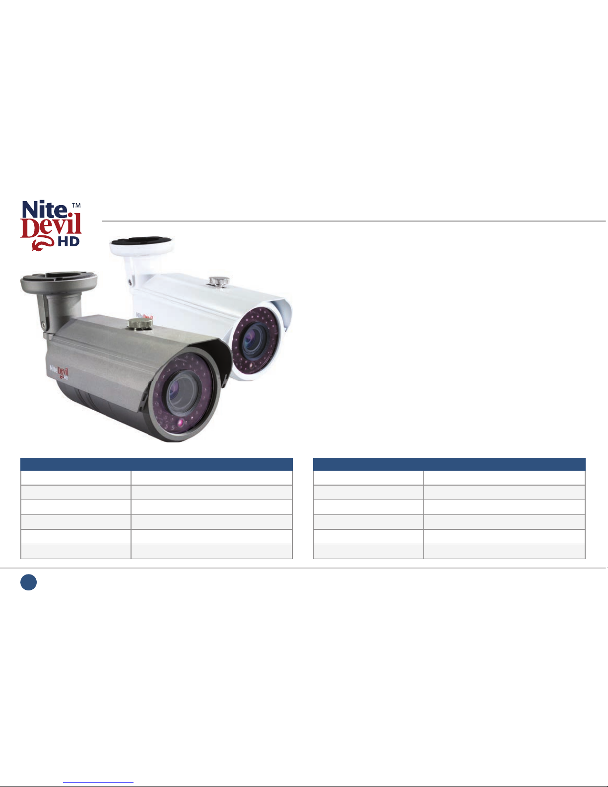
NiteDevil HD-SDI Cameras
Handbook &
Instructions
Manual Ref: XND-HD-02
Stunning 1080p HD-SDI cameras with built
in NiteDevil™technology.
Anti-Vandal
CAM320
All-In-On IR
CAM380
Traditional
CAM341-344
Mini Bullet
CAM360-362
Covert
CAM350-351
2Manual ref: XND-HD-01
Introduction
The ever impressive NiteDevil technology is now
built into a wide range of our HD-SDI cameras.
Our incredible 2.1 megapixel HD-SDI cameras record
1080p broadcast quality images at 25fps, that’s
20x the quality of the average analogue alternative.
Connect these cameras to one of our HD-SDI DVRs
and you’ll have an unrivalled CCTV system.
We offer a variety of HD-SDI cameras to suit any
environment, from tiny module cameras and mini
bullets to external all-in-one IR cameras.
As well as new systems, our HD-SDI cameras and alien
DVRs offer a potential upgrade opportunity as they
are designed to work over co-ax. By using co-ax cable
already installed for an old analogue system it’s easy
to make the transition to HD-SDI.
CAM380
- 2.1 Megapixel All-In-One IR
with a 2.8 - 11mm lens.

3
For more info, tips and advice visit nitedevil.com
Contents
Introduction 2
CAM320 - Anti Vandal HD-SDI Dome 4
CAM341-344 - Traditional HD-SDI Camera 8
CAM350/351 - Covert HD-SDI Modules 12
CAM360/362 - Mini HD-SDI Bullets 14
CAM380 - External HD-SDI All-In-One IR Camera 16
OSD Menus 20
Tips 28
Accessories 34

4Manual ref: XND-HD-01
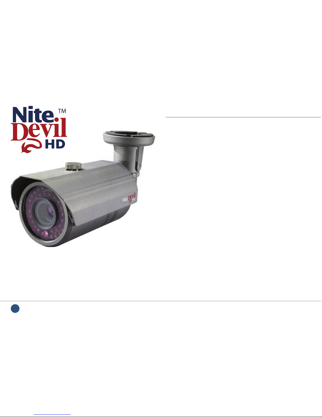
CAM320 - Anti Vandal HD-SDI Dome
With its 1080p high-res image quality, this camera outputs
the same stunning images as you would get from an HD TV
programme. Additional NiteDevil technology gives it great low
light performance.
Maximum IR
Sensitivity
FUNCTION SPECIFICATION
Imaging Sensor 1/3” 2.1M Megapixel CMOS
Resolution 1080p 25fps
Lens Type 2.8 - 11mm Vari-focal
Min. Illumination 0.02 Lux (Sens-up)
Input Voltage 12V DC/24V AC (Dual Voltage)
Current Consumption 150mA (12VDC) / 120mA ( 24VDC)
Features
• 1080p at 25fps
• Low light 0.02 Lux (Sens-up)
• Dual Voltage, 12V DC, 24V AC
• Digital 64x Zoom
• Privacy Masking
• Wide Dynamic Range
• Internal Wiring
FUNCTION SPECIFICATION
SN Ratio More than 50dB
IP Rating IP66
Gain Control Automatic
Video Connection HD-SDI BNC Socket
Power Connection Terminal Strip
Dimensions 144mm Dia x 100.5mm
Available with wall bracket

5
For more info, tips and advice visit nitedevil.com
CAM320 - Inside The Camera
1Focus Adjustment
Adjust the focus after adjusting the
zoom to get the perfect picture.
9Connection Block
Spring lock connections for easy wiring.
All wiring can be done inside the dome.
5Zoom Adjustment
Adjust the zoom in/out of the
camera by unlocking this screw. 6Tilt Axis
Unlock the side screws to tilt
the camera up and down.
7Rotational Axis
Turn this to rotate the camera’s
output image so that it is
correct on the monitor.
8Left-Right Axis
Simply unlock these screws to
adjust the left-right orientation
of the camera.
4Test Output
This handy Composite Video Output
means you don’t even need to come
down the ladder to test your setup!
2HD-SDI Video Out
Internal BNC connection
means all your wiring
remains inside the dome.
3Joystick
Use the joystick to navigate
the camera’s OSD menu.
Tilt Axis
Unlock the side screws to tilt
the camera up and down.
OSD
Menu &
Settings Guide
Starts On Page 20

6Manual ref: XND-HD-01
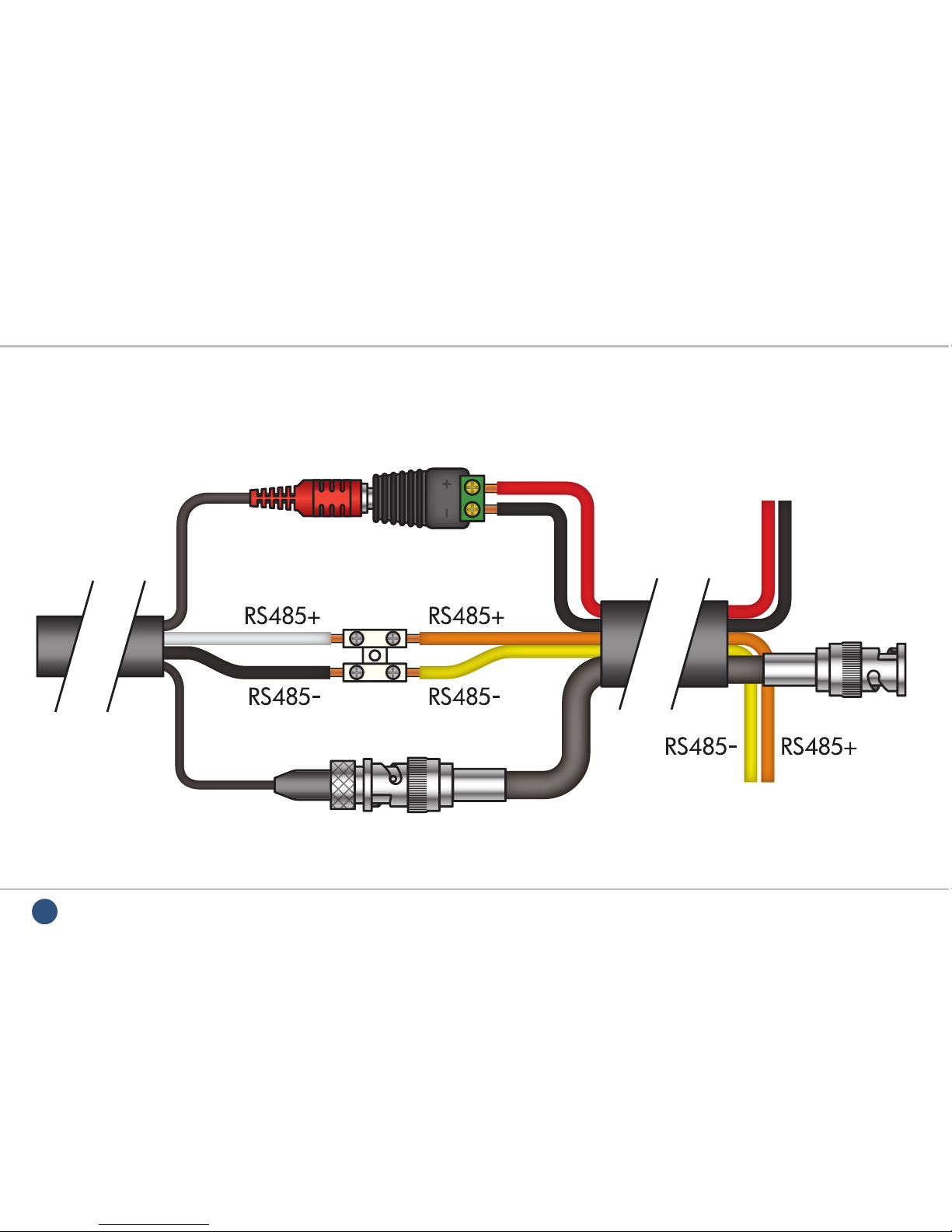
CAM320 - Connecting The Camera Using RG59+4 (PTZ Combo Cable)
The power connection terminals (marked in red) are
not polarity sensitive, therefore the power can be
connected either way round. However, the RS485
connections are polarity sensitive and must be
connected as shown in the diagram above.

7
For more info, tips and advice visit nitedevil.com
CAM320 - Mounting The Camera
The camera can be mounted on a wall, ceiling or attached to
an optional wall bracket.
To ensure that the camera is weatherproof, a rubber grommet
is provided through which the cable enters the camera.
Prior to the end of the installation you need to additionally
seal the grommet with a fl exible silicone product. This is because
the rubber grommet may shrink or get stressed over time.
The wall bracket helps
shield the camera
to prevent rain from
settling on the dome
and obscuring the
camera’s vision. It also
shelters the cable entry
point offering better
protection against the
elements.
Camera & Bracket
Order Code: CAM325
To ensure that the camera is weatherproof, a rubber grommet
is provided through which the cable enters the camera.
OSD
Menu &
Settings Guide
Starts On Page 20
Apply silicone here
Alternative cable entry point
(20mm Gland). If used must be
air/water tight. If not used must
be tight and silicone applied.
8Manual ref: XND-HD-01
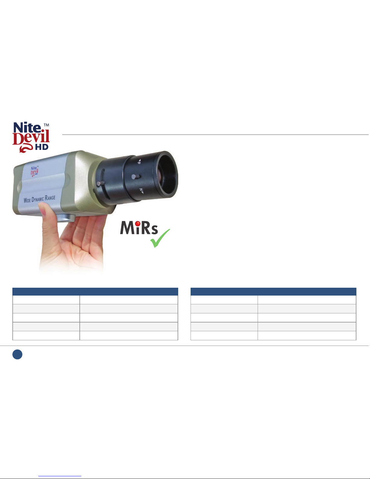
CAM341-344 - Traditional HD-SDI Camera
FUNCTION SPECIFICATION
Imaging Sensor 1/3” 2.1 Megapixel
Resolution 1080p 25fps
Lens Type 2.8 - 12mm Option Available
Min. Illumination 0.02 Lux (Sens-up)
Input Voltage 12V DC / 24V AC / 240V AC
Maximum IR
Sensitivity
Features
• 1080p at 25fps
• True Day-Night
• Wide Dynamic Range
•
Choice of 12V, Dual Voltage or 240V
• 0.02 Lux (Sens-up)
• Mirror / Privacy Function
• Motion Detection
A stylish high performance NiteDevil camera in a traditional
style features Wide Dynamic Range and OSD Menu for mirror,
privacy & motion detect functions. This true day-night camera
has a mechanical IR lter for superb nigh-time surveillance.
FUNCTION SPECIFICATION
Current Consumption 150mA
SN Ratio More than 50dB
Video Connection HD-SDI BNC Socket
Power Connection Terminal Strip
Dimensions 65mm x 60mm x 119.6mm (ex Lens)
9
For more info, tips and advice visit nitedevil.com
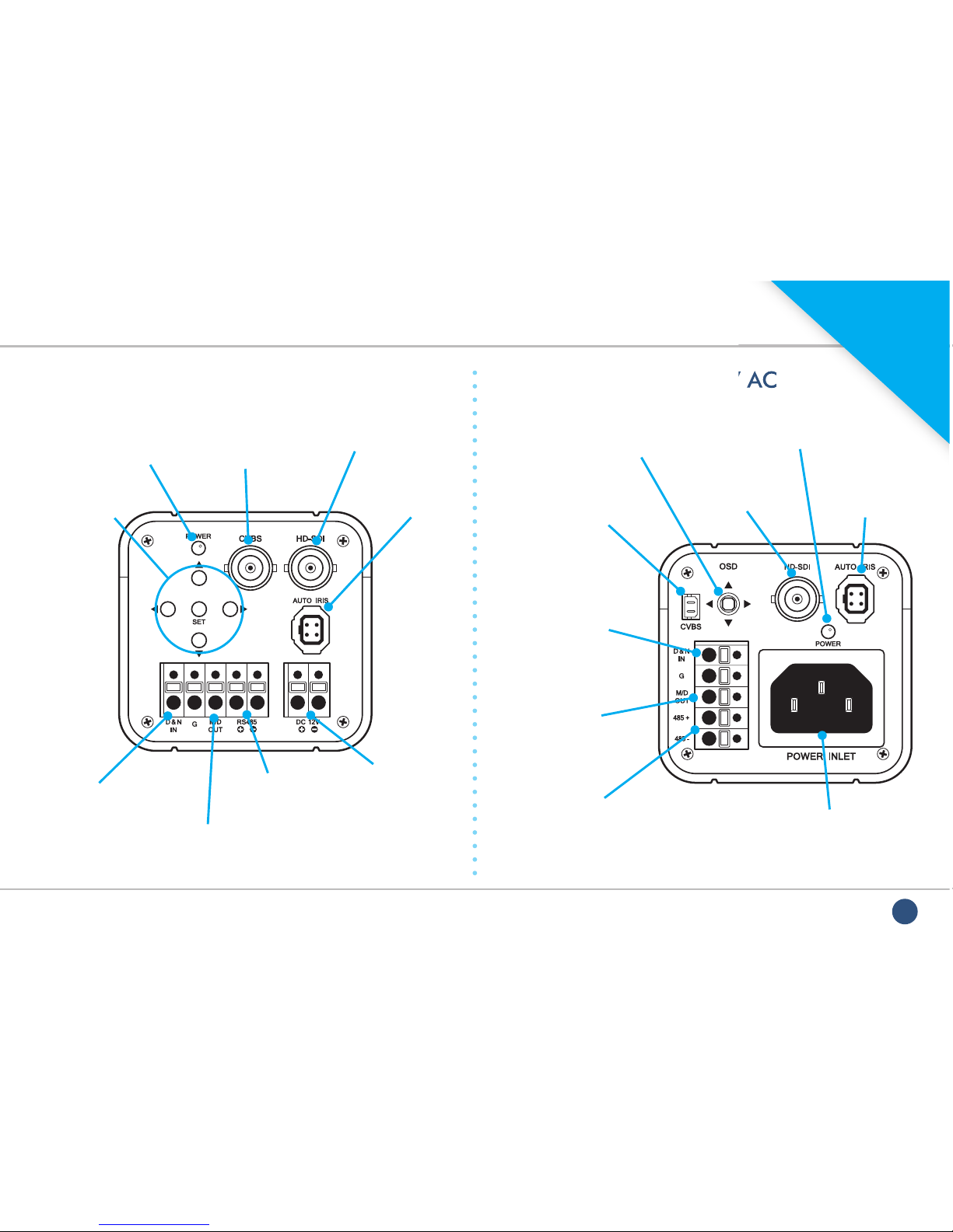
CAM341-344 - Connecting The Camera
CAM341 12V DC & CAM343 Dual Voltage
CAM345 - 240V AC
CAM345 - 240V AC
OSD
Menu &
Settings Guide
Starts On Page 20
Terminal socket for
when using an external
sensor to determine
day/night switch
Terminal socket for
when using an external
sensor to determine
day/night switch
Power input terminals.
Polarity sensitive on
the 12V DC model.
Min 200mA PSU
recommended
240V AC Power input.
C13 IEC Cable required.
RS485 + & -
terminals RS485 + & -
terminals
CVBS - Extra video
output for set up
on a test monitor
CVBS - Extra video
output for set up on a
test monitor (fl y lead
with BNC supplied)
High quality HD-SDI
out (BNC)
High quality HD-SDI
out (BNC)
Lens socket for
auto iris lenses
(see overleaf)
Lens socket for
auto iris lenses
(see overleaf)
Alarm out when
motion detection
is triggered
Alarm out when
motion detection
is triggered
Power LED - Red
when powered up
Power LED - Red
when powered up
OSD menu
selection buttons
OSD menu
selection joystick
10
Manual ref: XND-HD-01
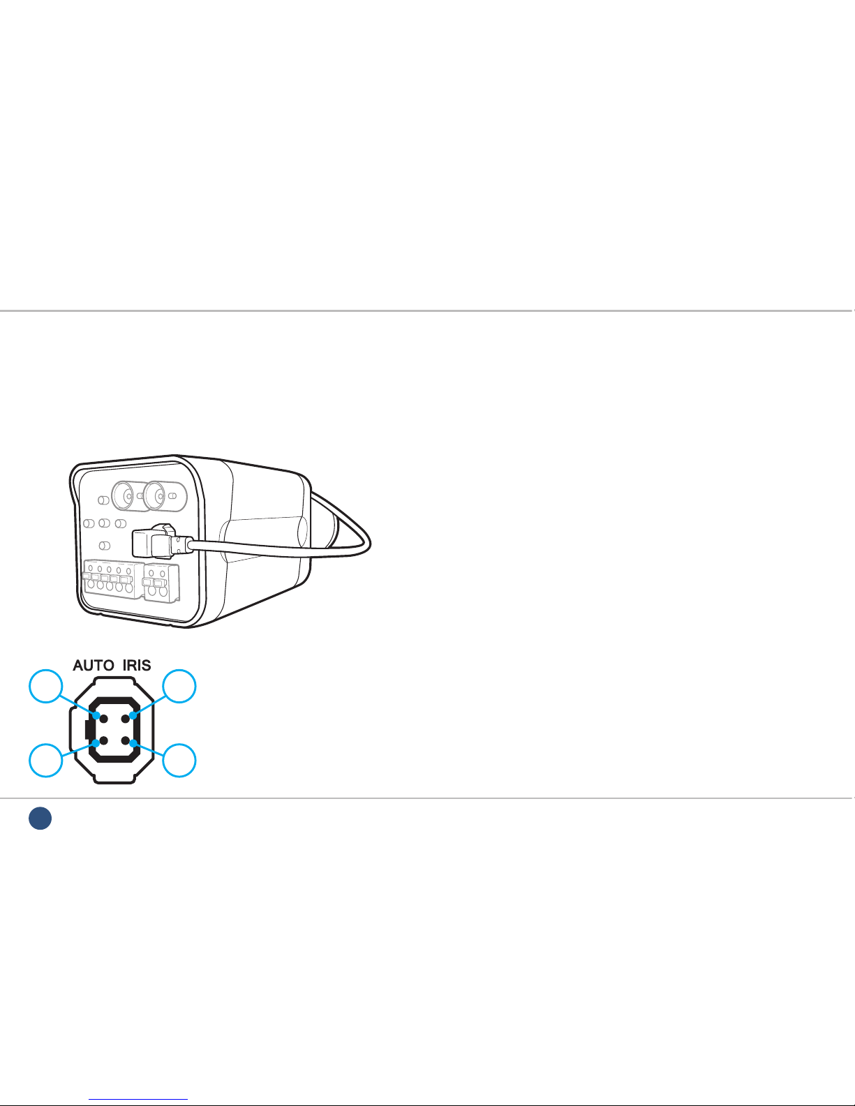
CAM341-344 - Fitting The Camera Lens
1 3
2 4
1. DAMPING-
2. DAMPING+
3. DRIVE
4. GND
Auto-Iris Direct Drive Connections
Auto Iris type lenses require the 4-pin connector to be attached
to the camera. In most instances your lens will be pre-wired with
this plug, but if needed on-line
Tip 322
which includes a full
wiring diagram can be found at
www.nitedevil.com
.
C Or CS Mount Lenses
Most lenses are available in 2 different mounting options - C mount
and CS mount.
CS mount lenses are now the most popular size as they are shorter
and more compact than C mount lenses. Most cameras are now
manufactured to accept CS mount lenses. Before tting the lens you
need to verify that you are using a CS mount lens with the camera.
You can conrm this with your lens supplier or the literature that
came with your lens, check the instructions or packaging to see if
your lens is a C or a CS mount version.
If your lens is a C mount type you can still t it to the camera. Please
see the on-line Tip 323 at www.nitedevil.com.
Using A CS Mount Lens
If you are using a standard CS mount lens you can screw the
lens straight into the camera without the need for the C-CS
adapter ring (supplied).

11
For more info, tips and advice visit nitedevil.com
CAM341-344 - Fitting The Camera Lens
C-mount to CS-mount
adapter ring supplied
Adjusting The Inner Focus Ring
Once you have tted the lens, if you have a picture on the
monitor but cannot correctly focus the lens by the ne focal
adjust on the lens itself, you may need to alter the inner
adjusting ring that is screwed into the end of the camera. This
ring enables the lens to either “sit” a little closer or a little further
away from the camera to get a sharp focused image when
using lenses from different manufacturers.
OSD
Menu &
Settings Guide
Starts On Page 20
To adjust the inner focus ring you will need to rst remove
the lens. Next loosen the small cross-head screw which in
turn loosens the inner focus ring as shown.
This is a trial and error process by moving the ring in or out say
by ½ turn then locking it again, re-attaching the lens and trying
to refocus. It is possible (with common sense!) to work out whether
the lens needs to be nearer or further away from the camera by
watching for improvements in focus at each attempt.
NOTE If it appears that the lens will never be in focus then it is
possible that you are trying to t a C-mount lens on the
camera, not a CS-mount lens. If this is the case you will
have to add the adapter ring to the lens that was provided
free with the camera. The adapter ring looks like this:

12 Manual ref: XND-HD-01
CAM350/351 - Covert HD-SDI Modules
FUNCTION SPECIFICATION
Imaging Sensor 1/3” 2.1 Megapixel
Resolution 1080p 25fps
Lens Type 3.7mm Board / 4.5mm Pinhole
Min. Illumination 0.02 Lux (Sens-up)
Input Voltage 12V DC
Features
• 1080p at 25fps
• Low light 0.02 Lux (Sens-up)
• Motion Detect
•
Privacy Masking
• Just 35.5mm Wide
• Wide Dynamic Range
• Mounting Bracket Included
NiteDevil HD-SDI covert camera module with on screen display
for mirror, privacy & motion detect functions. The light sensitivity
of the NiteDevil is so good that it can retain a colour picture in
very low light conditions making it ideal for dark and low light
applications. (FREE xing bracket)
FUNCTION SPECIFICATION
Current Consumption 150mA
SN Ratio More than 50dB
Video Connection HD-SDI BNC Socket (Moulded)
Power Connection 2.1mm 12V DC Socket (Moulded)
Dimensions 38 x 35.5mm
CAM350
Board Lens Camera
CAM351
Pinhole Camera
13
For more info, tips and advice visit nitedevil.com
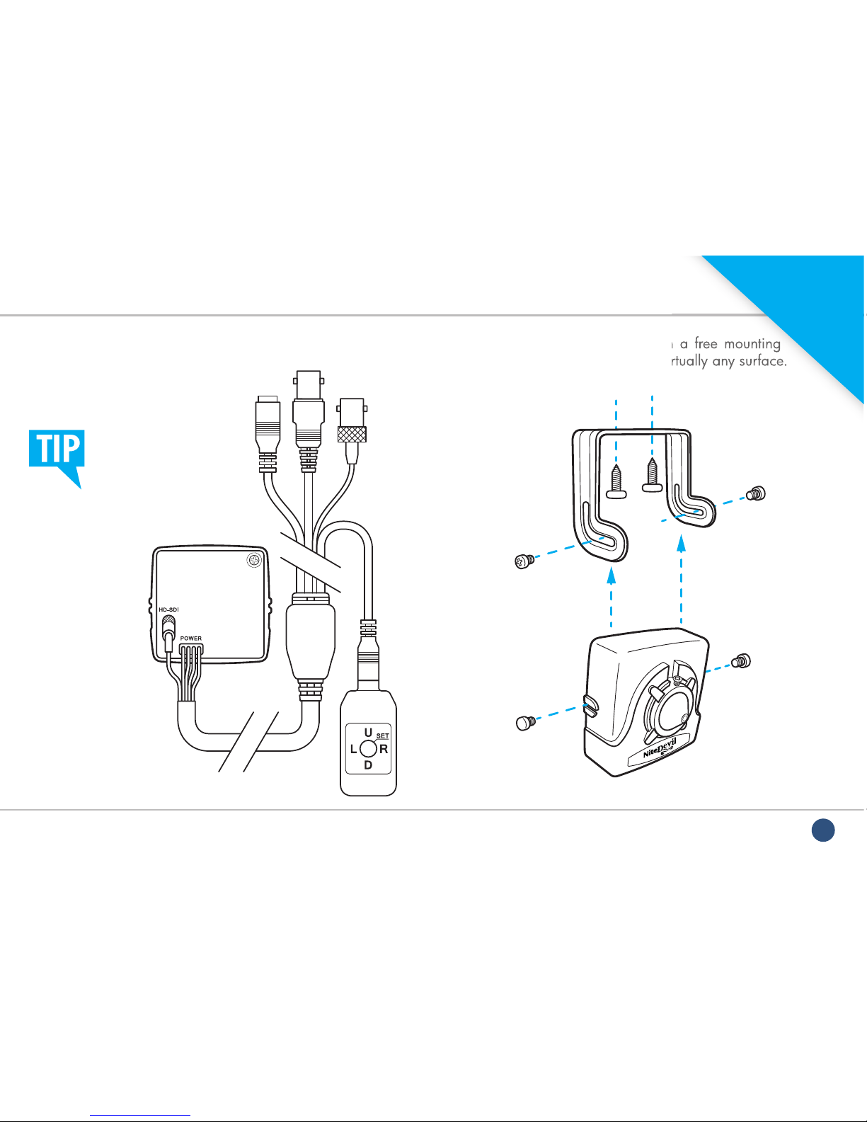
CAM350/351 - Connecting & Mounting
The CAM350/351 is supplied with a free mounting
bracket that can be easily xed to virtually any surface.
2.1mm 12V
DC Socket
HD-SDI
Output
OSD
Controller
CVBS Test
Output
A
A
B
B
The CAM350/351 has
a detachable OSD
controller to prevent
unauthorised access to
the camera’s settings.
The CAM350/351 is supplied with a free mounting
bracket that can be easily xed to virtually any surface.
OSD
Menu &
Settings Guide
Starts On Page 20

14 Manual ref: XND-HD-01
CAM360/362 - Mini HD-SDI Bullets
FUNCTION SPECIFICATION
Imaging Sensor 1/3” 2.1 Megapixel
Resolution 1080p 25fps
Lens Type 3.7mm Board / 4.5mm Pinhole
Min. Illumination 0.02 Lux (Sens-up)
Input Voltage 12V DC
Current Consumption 150mA
Features
• 1080p at 25fps
• Low light 0.02 Lux (Sens-up)
• Digital 64x Zoom
•Choice Of Lenses
•
Privacy Masking
• Wide Dynamic Range
• Removable Sun Shield
• Anti Vandal
• Bracket Included
The NiteDevil HD-SDI mini bullet cameras are a great option
when broadcast quality pictures are desired in discreet or covert
applications. Ideal for tight spaces measuring less than 12cm.
FUNCTION SPECIFICATION
SN Ratio More than 50dB
Video Connection HD-SDI BNC Socket (Moulded)
Power Connection 2.1mm 12V DC Socket (Moulded)
IP Rating IP66 (CAM360 Only)
Mounting Bracket Supplied
Dimensions
35mm x 125mm (Including Sun-shield)
CAM360
External Bullet With
3.7mm Board Lens
CAM362
Internal Bullet With
4.5mm Pinhole Lens

15
For more info, tips and advice visit nitedevil.com
CAM360/362 - Connecting & Mounting
The CAM360/362 has
a detachable OSD
controller to prevent
unauthorised access to
the camera’s settings.
2.1mm 12V
DC Socket
HD-SDI
Output
OSD
Controller
CVBS Test
Output
The CAM360/362 is supplied with a free mounting
bracket. A xing hole diagram is shown below to help
when tting the camera bracket.
The CAM360/362 is supplied with a free mounting
bracket. A xing hole diagram is shown below to help
OSD
Menu &
Settings Guide
Starts On Page 20
16 Manual ref: XND-HD-01
CAM380 - External HD-SDI All-In-One IR Camera
If you had any doubts over which model of HD-SDI camera to
install then this is a winning choice! The CAM380 has all the low
light surveillance bene ts of NiteDevil technology and a Wide
Dynamic Range with the added functionality of 40 IR LEDs.
FUNCTION SPECIFICATION
Imaging Sensor
1/3” 2.1M Panasonic Megapixel CMOS
Resolution 1080p 25fps
Lens Type 2.8 - 11mm Vari-focal
Min. Illumination 0 Lux (IRs On)
Input Voltage 12V DC/24V AC (Dual Voltage)
Current Consumption 170mA IR Off / 300mA IR On
Features
• 1080p at 25fps
• 2.8 - 11mm Vari-focal Lens
• Built-In IR LEDs
• True Day Night
•True Wide Dynamic Range
•62 x Digital Zoom PIP
• Dual Voltage, 12V DC, 24V AC
FUNCTION SPECIFICATION
SN Ratio More than 50dB
IP Rating IP66
Gain Control Automatic
Video Connection HD-SDI BNC Socket
Power Connection 2.1mm Socket
Dimensions 78mm Dia x 140mm (Ex Sun-shield)
CAM380W
Polar White
CAM380G
Graphite Grey

17
For more info, tips and advice visit nitedevil.com
CAM380 - Connecting & Mounting
12V DC / 24V AC
RS485 + (White)
RS485 - (Black)
HD-SDI Output
The CAM380 comes tted with an adjustable cable
managed bracket. Below is a diagram to help when
mounting the camera.
The CAM380 comes tted with an adjustable cable
managed bracket. Below is a diagram to help when
OSD
Menu &
Settings Guide
Starts On Page 20
Cable
Managed
Bracket
18
Manual ref: XND-HD-01
To DV
R or
Monitor
12V DC PSU
CON370 ZULUG
DC Plug with Terminal
Strip adaptor
From
Camera
HD-SDI
Terminal
Block
RS485 Keyboard
or Test Monitor
to control OSD
CAM380 - Connecting The Camera Using RG59+4 (PTZ Combo Cable)

19
For more info, tips and advice visit nitedevil.com
CAM380 - Camera Adjustments
The CAM380’s menu controls, zoom and focus adjustments
and CVBS test output are all cleverly hidden away inside the
camera. To access these features simply unscrew the front end
of the camera to reveal the lens and PCB.
Once the front end of the camera has been removed you
are then able to adjust the camera’s lens and menu settings.
Behind the IR LEDs you will see the menu control buttons
and test output as shown below. A fl ylead is supplied with the
camera for connecting the camera to a test monitor.
Tables showing the CAM380’s menu structure and options
available can be found on pages 21 - 27.
When screwing the front back onto camera, make
sure the seal is as tight as possible to prevent
moisture entering the camera.
If installed on a damp or humid day ensure you
wipe the inside of the camera with a dry, lint free
cloth to avoid any moisture being trapped inside.
Once the front end of the camera has been removed you
are then able to adjust the camera’s lens and menu settings.
Behind the IR LEDs you will see the menu control buttons
and test output as shown below. A fl ylead is supplied with the
camera for connecting the camera to a test monitor.
OSD
Menu &
Settings Guide
Starts On Page 20
20 Manual ref: XND-HD-01
Accessing The Menus
RS485
The CAM320 and the CAM341-344 range also has traditional
RS485 PELCO-D control and has terminals to connect the RS485
control device to. PTZ keyboards, some DVRs or the CCTVMate
test monitor all have RS485 control outputs that can control the
camera. This method can be useful to adjust cameras remotely
that are connected to DVRs.
To make life easier, all the HD-SDI cameras covered in
this book have virtually the same simple menu system.
You can access the menus in the camera in two ways:
LCD330
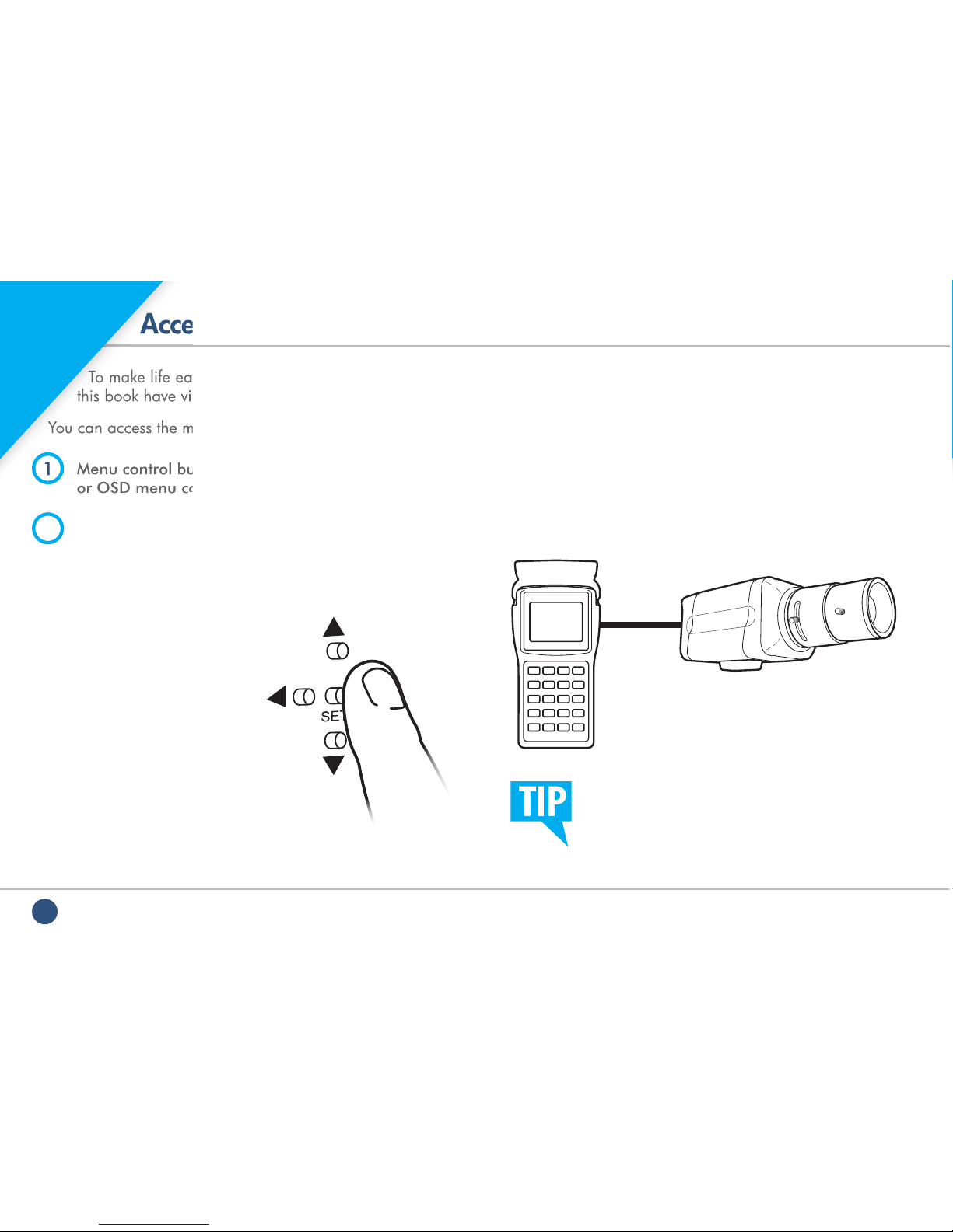
1Menu control buttons on the rear of the camera
or OSD menu controller.
2RS485 control using a keyboard, DVR,
or CCTVMate test monitor.
(CAM320, CAM341-344 & CAM380)
Menu Control Buttons
To access the menus using the
Menu control buttons or OSD
menu controller, simply press the
SET button down and the menu
will pop up on the camera’s
image. Use the arrow keys to
navigate through the menus.
Selection is made by pressing
the set button.
When using a test monitor you must use
the CVBS test output unless the test monitor
specifies it is HD-SDI compatible.
Accessing The Menus
To make life easier, all the HD-SDI cameras covered in
this book have virtually the same simple menu system.
You can access the menus in the camera in two ways:
1
Menu control buttons on the rear of the camera
or OSD menu controller.
OSD
Menu Guide
Starts Here!
This manual suits for next models
4
Table of contents


