Nitto ATRA ACE A-100 User manual

The specifications and configurations contained in this document are subject to
change without prior notice due to improvements we are making day in, day out.
Manufactured by :
Nitto Kohki Co., Ltd.
2-9-4, Nakaikegami, Ota-ward,
Tokyo, 146-8555, Japan
Tel : 81 (3) 3755-1111
Fax : 81 (3) 3753-8791
Keep the manual handy – so you can use it whenever necessary.
PORTABLE MAGNETIC DRILLING MACHINE
Read this manual careflly before operating your Nitto Kohki
Portable Magnetic Drilling Machine. Keep this manual with
your machine .All users of the Nitto Kohki Portable Magnetic
Drilling Machine must read this manual.
ATRA ACE Model A-100
Professional Tool For Side-Lock Type Annular Cutter Only
Specifications
Model A-100
Power Supply (Single Phase) 220-240 V AC 50/60 Hz
Drill motor
Rated Power Consumption 1600 W
Rated Current 7.4
No-load Speed 330 min-1
Magnet Power Consumption 80 W
Drilling Capability MAX. Hole diameter φ100 mm (3-15/16”)
MAX. Plate thickness 75 mm (2-61/64”)
Max Magnetic Force 17640 N
Magnet Size 134 x 256 mm (5-1/8”×10-5/64”)
Weight 50 kg (110.20lbs.)
A-100E.indd 1 12.11.28 2:26:01 PM

1
The following Safety notations are used throughout the manual to highlight safety precautions for the user and for
the machine.
DANGER: Indicates an imminently hazardous situation which, if not avoided by following the
instructions given, will result in death or serious injury.
WARNING: Indicates a potentially hazardous situation which, if not avoided by following the
instructions given, could result in death or serious injury.
CAUTION: Indicates a potentially hazardous situation which, if not avoided by following the
instructions given, could result in injury or material damage.
Caution: Important precautions for machine or tool setup, operation and maintenance.
Thank you very much for your
purchase of Nitto Kohki products.
Before using your machine, please
read this manual carefully so that you
may use it properly to get the most
out of it.
Please keep the manual handy - so
you can use it whenever necessary.
CONTENTS page
GENERAL SAFETY RULES ………………………………… 2
POWER TOOL SAFETY……………………………………… 3
ABOUT YOUR NITTO PORTABLE MAGNETIC
DRILLING MACINE ………………………………………… 4
1. APPLICATION …………………………………………… 7
2. RECEIVING INSPECTION ……………………………… 7
3. PART NAMES …………………………………………… 7
4. FUNCTIONS OF ELECTRONIC CONTROL ………… 8
5. MACHINE SETUP ……………………………………… 8
6. MACHINE OPERATION ……………………………… 10
7. TROUBLESHOOTING ……………………………… 13
8. MAINTENANCE/SERVICE …………………………… 14
9. OPTIONAL PARTS …………………………………… 15
10. EXPLODED DIAGRAM: MACHINE ………………… 16
・English :Please ask your dealer or
distributor for instruction manual
in local language(s).
・German :Bitte fragen Sie lhren Händler
nach eine Betriebsanleitung in
Landessprache.
・French :S'il vous plait, veuillez demandez
á votre foumisseur de manuel
instruction en langue locale.
・Spanish :Por favor, cantacte con su
distribuidor para el manual de
instrucciones en español.
・Portuguese :Por favor pessa ao seo agente
ou distribuidor o manual de
instrucces ih linguagen local.
・Italian :Per Manuale lstruzioni in lingua
locale Vi preghiamo di rivolgervi
al rivenditore o distributore.
・Dutch :Vraag uw handelaar
om een nederladstalige
gebruiksaanwijzing.
・Swedish :Be er lokala Åtreförsäljare eller
distributör om manualer pá
svenska.
・Danish :Venligst henvend Dem til den
danske distributør for instructions
manualer.
・Polish :Prosze pytac swojego dealera
lub dystrybutora o instrukcje
obslugi w jezyku localnym.
・中文 :
A-100E.indd 1 12.11.28 2:26:02 PM

2
GENERAL SAFETY RULES
WARNING
TO OPERATORS
Always Wear Proper Clothing
●Do not wear loose clothing. Loose clothing can
become caught in the drilling machine. This could
cause severe injuries. Be careful that loose clothing
does not come into contact with the machine.
●Wear non-skid footwear. If you lose your footing,
you could contact moving portions of the machine.
This could cause severe injuries. Always wear non-
skid footwear and remain balanced when using the
drilling machine.
●Be careful of long hair. Wear a hat or a hair net to
contain long hair. Long hair can become caught in
the drilling machine. This will cause severe injuries.
Be careful that long hair does not come into contact
with the drilling machine.
Always Wear Safety Glasses
●Always wear safety glasses. The operation of your
drilling machine will cause flying chips and particles.
These will cause severe eye injuries. You must
always wear safety glasses.
● Not all glasses are safety glasses. Wear only safety
glasses that comply with ANSI standards. Not all of
the lenses are shock resistant. Ordinary glasses will
not provide sufficient eye protection.
Always Wear Hearing Protection
●Always wear hearing protection. The operation of
your drilling machine will cause big sound occurs.
These will cause severe hearing loss injuries. You
must always wear hearing protection
Wear respiratory protective equipment (PPE)
●Wear respiratory protective equipment (PPE) when
working in an environment where dust particles are
generated in operation.
Maintain Good Posture
●Always wear non-skid footwear and maintain good
posture. Do not use the drilling machine when you
are tired. Fatigue or loss of balance could cause
you to lose control of the machine. This could cause
severe injuries. Always stay balanced. Always keep
good posture. Stop using the machine if you are
tired.
Never Touch the Cutting Tip
●Never touch the moving or cutting tip. Contact with
the moving tip will cause severe injuries. Always
keep all parts of your body away from the cutting tip.
Always keep your hand and clothing away from the
cutting tip.
ABOUT THE WORK AREA
Keep Work Area Clean
●Always keep your work area clean. Cluttered work
areas cause accidents. Always keep clear of other
objects.
● Never use the magnetic drilling machine when it is
wet. Always use the drilling machine in a dry area.
Do not use the drilling machine in the rain. If you use
the machine when it is wet you can get an electric
shock. If you use the machine in the rain you can
get the electric shock.
● Always use the drilling machine in a well-lighted
area. Do not use the drilling machine in the dark.
● Avoid all flammable materials. Use of the drilling
machine may cause a spark that could ignite a fire
or an explosion. Never use the machine near any
flammable material.
● Keep away from children. Always keep the drilling
machine away from children. Do not operate drilling
machine when children are present.
BEFORE OPERATION
Make sure that all parts are free from damage
● Make sure that the drilling machine is in good
operating condition. Operation of a damaged
machine could result in severe injuries. If there
is any damage to the machine, do not use the
machine. If there is any damage to the machine,
take it to an authorized Nitto dealer for repair.
● Do not attempt service or repair of the drilling
machine. All service or repair should be done by an
authorized Nitto dealer.
Secure Your Work
● Always secure your work piece. Improperly mounted
work can become loose. This can cause severe
injuries. Always secure all work.
● Always use a vice or a clamp. Do not attempt to
hold any work piece with your hand. Attempting to
hold a work piece with your hand may cause severe
injuries. Always use a vice or clamp to hold the work
piece.
● Always secure your drilling machine. Improperly
mounted drilling machine can come loose. This can
cause severe injuries. Always secure the drilling
machine.
Avoid Clutter
● Always stay clear of other objects. Cluttered work
areas cause accidents. Always keep a clean work
area and stay away from other objects.
Always Remove Spanner Wrenches and
Adjustment Tools
● Always remove spanner wrenches and adjustment
tools after adjustments have been made to the
A-100E.indd 2 12.11.28 2:26:02 PM

3
drilling machine. Always remove all adjustment tools
before using the drilling machine.
Always Use a Cutter that is Appropriate for Your
Work
● Always use a Cutter that is appropriate for your
work. Avoid heavy-duty work that is beyond the
capacity of your drilling machine. If the work exceeds
the capacity of your drilling machine, this can cause
accidents and severe injuries. Always use the
drilling machine in accordance with its performance
specifications.
SAFE HANDLING
● Never leave the magnetic drilling machine
unattended while it is running. When the machine
is unattended, disconnect the power source. Do
not leave the work area until the machine comes to
a complete stop. Operating the machine while it is
unattended can case accidents that may result in
severe injuries.
HOW TO STORE YOUR MAGNETIC DRILLING
MACHINE
● Always store the machine in a dry area.
● Always keep the machine out of the reach of
children.
HOW TO CARRY YOUR MAGNETIC DRILLING
MACHINE
● Disconnect the power and turn off the machine
whenever you carry the machine.
MAINTENANCE
Do not take apart or modify your magnetic drilling
machine.
● Do not attempt to disassemble or modify your
magnetic drilling machine.
● Do not modify your magnetic drilling machine.
Modifications can cause accident and severe
injuries.
● All service and repairs must be performed by an
authorized Nitto dealer. Any attempt to service or
repair the machine yourself may result in an accident
and severe injuries.
Check all Parts for Damage.
● Always inspect the magnetic drilling machine before
use.
● Always check that the pilot pin and cutter are in
good condition. Use of the machine with worn pilot
pins or worn cutter can cause accidents and severe
injuries.
● Inspect all cutter before you put them on the
magnetic drilling machine.
● Do not operate the magnetic drilling machine with a
damaged or worn cutter. Do not operate the machine
with a damaged or worn pilot pin. Do not operate the
machine with any damaged accessory. Operating
the machine with any damaged part or accessory
can cause accidents and severe injuries. If there is
any damage to the magnetic drilling machine, do not
operate the machine. Take it to an authorized Nitto
Dealer for repair.
● Always have the magnetic drilling machine repaired
at an authorized Nitto dealer. Always take the
magnetic drilling machine to an authorized Nitto
dealer for service, repair and replacement parts. If
you cannot locate an authorized Nitto dealer near
you, please contact your sales representative.
● Always use Nitto genuine parts. The use of improper
or non-Nitto parts can cause accidents and severe
injuries. Never use unauthorized parts. To obtain
genuine Nitto parts, contact your sales agent.
● Do not remove any nameplate from your magnetic
drilling machine. Do not remove any labels from
your magnetic drilling machine. If any label or
nameplate is damaged contact your sales agent for
a replacement.
POWER TOOL SAFETY
WARNING
● Always make sure that the machine is properly
grounded. If the machine is not properly grounded,
someone can get an electric shock.
● If you have any doubt about the grounding of
the magnetic drilling machine, contact a licensed
electrician.
● Never connect the grounding conductor to a gas
pipe. This will result in an explosion and severe
injuries or death.
● Always check the grounding conductor. If you have
any doubts about the grounding conductor, contact
a licensed electrician.
● Wiring connections to a grounding rod require the
expertise of a licensed electrician. Do not attempt
the wire connections yourself. Always contact a
licensed electrician.
● Do not abuse the power cord. A damaged power
cord can cause an electrocution. A damaged power
cord can cause fires. Always inspect the cord. If the
cord is damaged, do not use the magnetic drilling
machine.
● Do not carry the machine by the cord. Do not pull
the cord to disconnect it from a socket.
● The cord can become damaged from heat, contact
with sharp objects or from being twisted. Always
inspect the cord. Do not use the machine if the cord
A-100E.indd 3 12.11.28 2:26:03 PM

4
is damaged.
● Always use a ground fault circuit interrupter. The use
of a ground fault circuit interrupter may be required
by government regulations. The failure to use a
ground fault circuit interrupter may result in electric
shock.
● Avoid starting the magnetic drilling machine abruptly
or unintentionally.
● Always make sure that the switch is turned off before
connecting the power source.
● Always disconnect the power source and turn off
the switch before setting up for work operations.
Always disconnect the power and turn off the
switch when inspecting work. Always disconnect
the power and turn off the switch before attempting
any maintenance. Failure to disconnect the power
and turn off the switch during set up, inspection
or maintenance can cause accidents and severe
injuries.
About Your Nitto Portable Magnetic
Drilling Machine
DANGER
Do not use your portable drilling machine on the
ceiling and the side.
● Use of the portable drilling machine on the ceiling or
the side is dangerous. The machine could fall. The
falling machine could cause severe injuries or death.
(Fig.1)
Fig. 1
WARNING
Do not use the Magnet for more than five hours.
● More than five hours of uninterrupted operation may
cause a fire. Five hours of uninterrupted operation
generates extreme heat in the Magnet. This heat
can cause a fire. Do not touch the Magnet. When
the Magnet is hot, touching it will cause a severe
burn injury. Never use the Magnet for more than
five continuous hours. When you are not using the
Magnet, turn the switch to the OFF position and pull
the Plug out of the power source.
Do not use the Drill Motor for over 30 minutes.
● Uninterrupted operation of the Drill Motor for over 30
minutes generates heat. This heat can cause a fire.
Never use the Drill Motor for over 30 minutes. When
you are not using the Drill Motor, turn the switch to
the OFF position and pull the Plug from the power
source.
Use only on magnetic materials.
● Your portable drilling machine cannot be used
on non-magnetic materials, such as aluminum,
stainless steel, copper or alloys. The Magnet will not
work on non-magnetic materials. Attempting to use
the Magnet on non-magnetic materials could cause
an accident.
Use caution during wall operation.
● When using your portable magnetic drilling machine
on a magnetic wall, always use caution.
● Never stand under the machine.
* Never allow anyone to stand under the machine.
* Never put any part of your body under the
machine.
* If the machine falls, it could result in severe injury
or death.
Always use a work piece that is at least 13 mm
(33/64”) thick.
● The work piece must be at least 13 mm (33/64”)
thick. If a work piece is too thin, the magnetic power
of your machine will decrease. This will cause the
machine to move during operation. This could result
in an accident. (Fig.2)
Not less than 13mm (33/64”)
Fig. 2
Use an iron back-up plate.
● If the work piece is less than 13 mm (33/64”) thick,
you must use an iron back-up plate that is more
than 10 mm (13/32”) in thickness. The surface area
of the iron back-up plate must he greater than the
surface area of the magnet. An appropriate back-up
plate is necessary to boost the holding power of the
Magnet. (Fig.3)
Use of an inappropriate back-up plate can result in
A-100E.indd 4 12.11.28 2:26:04 PM

5
an accident, If the back-up plate is not thick enough
or big enough, the machine will come loose during
operation. This can result in an accident and severe
injuries.
Place 10mm(13/32”) or
more thick piece iron
Less than 13mm (33/64”)
Fig. 3
Always keep surfaces clean.
● Always keep the Magnet surface clean. Always keep
the work piece surface clean. If there are any foreign
objects between the Magnet and the work piece
surfaces, this will reduce magnetic power. This could
cause the machine to move during operation. This
can result in an accident. Keep all surfaces clean of
rust, chips or other foreign material.
Do not place the machine over a hole.
● Do not attempt to position the Magnet over a hole.
Attempting to straddle a hole will reduce the power
of the Magnet. This will cause the work piece to
come loose during operation and can cause an
accident.
Always use a Chain to secure the machine.
● If the machine falls, it can cause severe injuries.
There is always a possibility that magnetic power
can be lost or reduced because of a power failure.
Magnetic power can be lost on rough surfaces. You
must take precautions to prevent the machine from
falling.
● This machine comes with a Chain. The chain is to
be used to fasten the machine to the work piece.
If you do not use the chain, it is possible that the
machine may fall. (Fig.4)
Fig. 4
Always set the Magnet in the proper position.
● Always set the Magnet parallel to the longitudinal
direction of the material. Failure to set the Magnet in
the proper position may result in reduced magnetic
power. This can cause the machine to move in
operation. This can cause an accident resulting in
severe injuries.
● When using on H-section steel, as shown in the
figure below, set the Magnet in a direction parallel
to the longitudinal direction of the material. This will
ensure that the Magnet is in the best position for
magnetic attraction.(Fig.5)
● Poor magnetic power may result in damage to the
cutter or damage to the work piece.
Wrong Right
Fig. 5
Stabilizer adjustment
The Stabilizer serves as the effective counterbalance
to the adhesive force of the Magnet. After switching
on the Magnet, adjust it so that the Magnet clings to
the work piece evenly without a gap. Make sure the
Stabilizer Wheels are not protruding and lifting the
Magnet off the plate.
Right
Maintain solid contact
Fig. 6
Wrong
Improper contact
Fig. 7
A-100E.indd 5 12.11.28 2:26:06 PM

6
Wrong
Protruding Stabilizer Wheels
lifts up the Magnet
Fig. 8
Be careful about chips.
● Keep your hands away from the cutting area at all
times. During drilling, there will be chips. The chips
are sharp. The chips are rotating with the cutter. Any
contact with the chips can cause severe injuries.
Do not touch the slug.
● Do not touch the slug. The slug is very hot. It will
cause severe burns. Make sure that no one touches
the slug. Make sure that there is no one below the
work area during operation. Hot slugs will fall. Hot
slugs can cause severe burns, other severe injuries,
or even death. Always wear protective equipment,
including protective headgear, eye protection,
hearing protection, and gloves. Do not allow any
person without protective equipment to come near
the machine.
Do not use your hands to remove chips.
● Chips have sharp edges. Use a screwdriver to
remove chips. If you use your hands to remove
chips, you can be injured, even if you are wearing
gloves. Do not use your hands to remove chips
under any circumstances.
The cutting edge is sharp.
● Always wear gloves when changing the cutter. The
cutting edge is sharp. If you do not wear gloves,
you will be cut. Attempting to change the cutter can
result in severe injuries.
Do not use Cutting Oil for other purposes.
● Cutting Oil should be used only for drilling. Please
refer to Section 5-4 of this manual for further
warnings and instructions about Cutting Oil.
CAUTION
Always use a compatible Pilot Pin.
● The Pilot Pin must be compatible with the cutter. An
improper Pilot Pin may result in an accident.
Do not use power that is generated by an engine-
driven welder.
● The use of an engine-driven welder as a power
source may cause your magnetic driven machine
to malfunction, Power from an engine-driven welder
can damage the electronic circuits in your portable
drilling machine.
Use a Proper extension cord.
● Do not use an extension cord that is too thin. Do
not use an extension cord that is too long. Do not
use an extension cord that is wound on a drum. Do
not share an extension cord with other motor-driven
tools. These uses can cause voltage to drop and
can reduce the holding power of the magnetic base,
causing the machine to move during operation. This
can decrease performance and may cause damage
to the machine. (Fig.9)
Extension Cord
Max. length Size (nominal cross-section
area of the conductor)
10 m Min 2 mm2or more
20 m Min 3.5 mm2or more
Fig. 9
Do not use this machine on the steel material
being electrically welded.
● When the electric welder is not properly grounded,
electricity will run through the Atra Ace machine
via its Magnet, causing possible failure or
malfunctioning, which in turn may cause accident.
Do not force to feed cutter.
● Because the Jetbroach has rather thin cutting edges
with less cutting pressure resistance as compared to
twist drill, do not force to feed the cutter.
If you feed it with too much force, the cutter may
break or end up with shorter life than otherwise.
A-100E.indd 6 12.11.28 2:26:07 PM

7
1 APPLICATION
This is a portable drilling machine with a Magnet,
geared to drilling mild steel (mild steel or equivalent)
using One-Touch type Jetbroach or twist drill. The
machine will be mounted on the workpiece to be
drilled with the Magnet securely fastening the machine
to the workpiece while drilling takes place.
2 RECEIVING INSPECTION
Upon unpacking, check to see that the shipment is
complete without damage or oil leakage in transport.
Should you find any damage or short-shipment,
please contact sales agent through which you have
purchased your machine or an authorized dealer near
you for corrective actions.
Part Name Q’ty Check
ATRA ACE 1set
Hex. Socket Screw Key 2 1
Hex. Socket Screw Key 2.5 1
Hex. Socket Screw Key 3 1
Hex. Socket Screw Key 4 1
Hex. Socket Screw Key 5 1
Hex. Socket Screw Key 6 1
Hex. Socket Screw Key 8 1
Spanner 7X8 1
Tool Box 285X125X62 1
Safty Chain Ass'y 1set
Soluble Cutting Oil 0.5 Ass'y 1set
Instruction Manual 1
Feed Handle 3
Oil Cup Ass'y 1
Pilot 12075 Ass'y 1set
3 PART NAMES
Fig. 10
Drill Mortor
Trigger Switch
Set Screw
Lamp
Dial Switch
Magnet
Stabilizer
Plug
Body
Feed Handle
Overload
Warning Lamp
Slide Board
Ajustment Screw
A-100E.indd 7 12.11.28 2:26:08 PM

8
4 FUNCTIONS OF OVERLOAD DETECTOR
● When overload occurs during drilling, the overload
detector puts the following functions to work.
4-1. Overload Warning Light
The lamp on the top of the unit body will be lighted
up in red when the overload detector catches the
overload on the drill feed. As soon as the lamp is
turned on, reduce the drill feed.
4-2. Automatic Stop
If the feed is further increased, the Electric Drill
would stop automatically and the red Overload
Detector Lamp would not go out.
After the Electric Drill stops, return the Main Dial
Switch to the “Magnet ON” position and lift the
Electric Drill up by turning the feed handle inversely
in order to make a thorough check of the unit based
on our checklist.
4-3. Checklist
Check Items Solutions
Feed speed Reduce feed speed
slower as the hole to
be cut comes bigger.
Check if the work piece is
extraordinary hard.
Reduce feed speed
when the work piece
is so hard.
Check if the lubrication is
good enough.
Increase the supply
volume of cutting oil.
C h e c k t o s e e i f
JETBROACH is in good
condition
Clean the blade tips
and re-sharpen them
if they are worn out.
To continue drilling the remaining workpiece after
inspection, eliminaite chips and slowly feed the
handle up to 2 to 3 mm at the beginning of drilling.
5 MACHINE SETUP
5-1. Mounting the accessory to the body
(1) Screw the feed handles into the handle boss
tightly.
(2) Fix the cup holder on the slide plate with the
Hex. Socket Head Cap Screw.
(3) Fix the oil cup on the cup holder.
(4) Couple the oil cup and oil ring to the oil dropper
with the tube and put soluble cutting oil diluted 8
to 10 times into the oil cup.
Handle boss
Oil cup
Cup
holder
Hex. Socket
Head Cap
Screw
Tube
Oil ring
Oil dropper
Feed handle
Fig. 11
WARNING
●When setting up machine, turn off the Magnet
Switch and disconnect the power supply plug
from power source.
5-2. Using Cutter
CAUTION
● Use side lock type cutters only.
●
For better workability and safety, do not use
worn out or damaged cutters.
5-3. Mounting/Removing Cutter
WARNING
●
Wear safety gloves when replacing cutter.
JETBROACH installation.
(1) Put the Pilot Pin into the JETBROACH you will
use.
Pilot Pin
JETBROACH
Fig. 12
(2) Insert the JETBROACH into Arbor shank with the
two flat surfaces are respectively and properly
aligned to the setscrew holes.
Setscrew hole
Flat surfaces
Fig. 13
A-100E.indd 8 12.11.28 2:26:09 PM

9
(3) Initially put 2pcs.of Hex. Socket Setscrews into
each hole tentatively (with careful attention to the
fastening threads), then tighten them firmly with
Hex. Socket Screw Key.
Hex. Socket Setscrews
Hex. Socket Screw Key
Fig. 14
(4) If the JETBROACH is inserted without proper
alignment of Hex. Socket Screws, the Hex. Socket
Screws will contact and clutch other part than flat
surfaces and the JETBROACH may not be taken
off.
Wrong
Right
Fig. 15
5-4. Preparation of Cutting Oil
Cutting Oil Safety Precautions
WARNING
(1) Use
● Use Cutting Oil for cutting purpose only. Don’t use it
for household purposes
(2) Handling Precautions
● The Cutting Oil contains amine. Do not mix it up with
rust inhibitor, etc. containing nitrite.
● Wear safety glasses for eye protection when
handling Cutting Oil: eye injury may results if it gets
into your eyes.
● Wear protective gloves for hand protection when
handling Cutting Oil: skin injury may result if it
comes into contact with your skin.
● Wear respirator when exposure to respiratory
hazards with oil mist or vapor is anticipated.
Inhalation of oil mist or vapor may make you feel sick.
● When diluting Cutting Oil, follow the instructions per
the Operation Manual.
● Keep Cutting Oil out of reach of children.
● Don’t drink Cutting Oil.
(3) First Aid
● If Cutting Oil gets into your eyes, immediately open
your eyelids with your fingers and wash your eyes
with plenty of water for at least 15 minutes. If your
eyes feel irritated, consult with a medical doctor and
follow his/her instructions.
● If Cutting Oil comes into contact with your skin,
immediately wash it away with plenty of water and
soap. Take off contaminated clothes. Clean the
clothes if you need to wear it again. If your skin feels
irritated, consult with a medical doctor for medical
instructions.
● If someone inhales oil mist or vapor, immediately
take him/her to an area where fresh air is abundant
and wrap up his/her body with a blanket, etc. to
keep body temperature. Have him/her take a rest
and consult with a medical doctor for medical
instructions.
● If someone drinks Cutting Oil, immediately make
him/her drink plenty of water and vomit it. Consult
with a medical doctor for medical instructions. When
unconscious, do not pour water into his/her mouth
nor induce him/her to vomit.
(4) Instructions in Case of Fire
● If fire breaks out in the vicinity, wear PPE (personal
protective equipment) and use foam, powder or
CO2fire extinguisher to put the fire out from the
windward.
(5) Storage
● When storing Cutting Oil after use, put it into a
container and put a lid on for tight sealing so
that dust or moisture, which is a catalyst for
contamination, may not get in.
● Avoid direct sunlight, rainwater or the like and store
Cutting Oil a dim cool area.
(6) Disposal
● For disposal of concentrate solution and used fluid,
request a waste-disposal company to dispose them
as industrial waste in accordance with the local laws
and regulations.
● Treat flushing water through pH adjustment,
condensation/sedimentation, activated sludge
process, activated carbon adsorption, etc., and
discharge it in accordance with the regulations of
your local municipal bylaw.
● Residual dross will remain in an emptied container:
be careful when handling an empty container.
(7) Others
● When Cutting Oil is poured into another container
A-100E.indd 9 12.11.28 2:26:09 PM

10
for use, post chemical and label information at the
site where it is kept. At the same time, keep the
Operation Manual handy so that can be referred to
whenever necessary.
● For further details, contact us for product safety data
sheet.
● All the information and descriptions that have been
provided are based on the currently available
documents and information, which may be revised
upon our new recognition and/or discovery.
● The precautions provided apply to regular handling.
If special handling method is used, take safety
measures that are suitable for your applications and
usage.
● The information contained herein is for your
reference purpose only, to which we make no
warranty of any kind and for which we shall not be
held responsible.
Preparation of Cutting Oil
(1-1) Use our genuine-product Cutting Oil (blue).
If other Cutting Oil is used, the cutting
performance and service life of cutter would be
decreased.
(1-2) Use tap water to dilute Cutting Oil by 8- to
10-fold. Do not use well water.
6 MACHINE OPERATION
WARNING
●
Always Wear Safety Glasses.
●
Always Wear Hearing Protection.
●
Wear respiratory protective equipment.
●
Never touch the mounted cutter and the rotating
parts of the machine such as the Spindle Arbor
after the power cable is connected to power
source.
6-1. Start and Stop
●
The Drill Motor will not rotate unless a Magnet
is turned on in operating the Motor Switch.
CAUTION
●
When the Trigger Switch of the Electric Drill
is not turned on, the Electric Drill will not start
even the Main Dial Switch on the side of the
body is turned to the “Drill ON” position. Leave
the Trigger Switch on during the entire drilling
work.
●
When turn on both the Magnet and Electric Drill,
pause momentarily at the “Magnet ON” position
before switching over to the next “Electric Drill
ON” position. Unless the Main Dial Switch is
steadily set to its ON stage once, the Electric
Drill may not start.
(1) Trigger Switch of the Electric Drill ON
Turn on the Trigger Switch. Turning on the Trigger
Switch alone would not let the Electric Drill start.
Trigger Switch
Fig. 16
(2) Magnet ON
First turn the Main Dial Switch to the “Magnet ON”
position. The power lamp will come on and the
Magnet will be activated.
Lamp
Drill Motor
Magnet
Fig. 17
(3) Electric Drill ON
Then set the Main Dial Switch to the “Motor ON”
position. The Electric Drill will start to run.
Drill Motor
Magnet
Fig. 18
(4) All Stop
When the Main Dial Switch is pulled back from
the “Electric Drill ON” position to the “Magnet ON”
position, the Electric Drill will stop. When the Main
Dial Switch is pulled further back from “Magnet
ON” position to the “All OFF” position, the Magnet
will be deactivated and all functions will stop.
6-2. Drilling Procedure
(1) Punching
The punch mark should be stamped quite vertical
to the work piece and rather large in size. Be
careful to get precise punch mark since it serves as
the drilling center guide.
A-100E.indd 10 12.11.28 2:26:10 PM
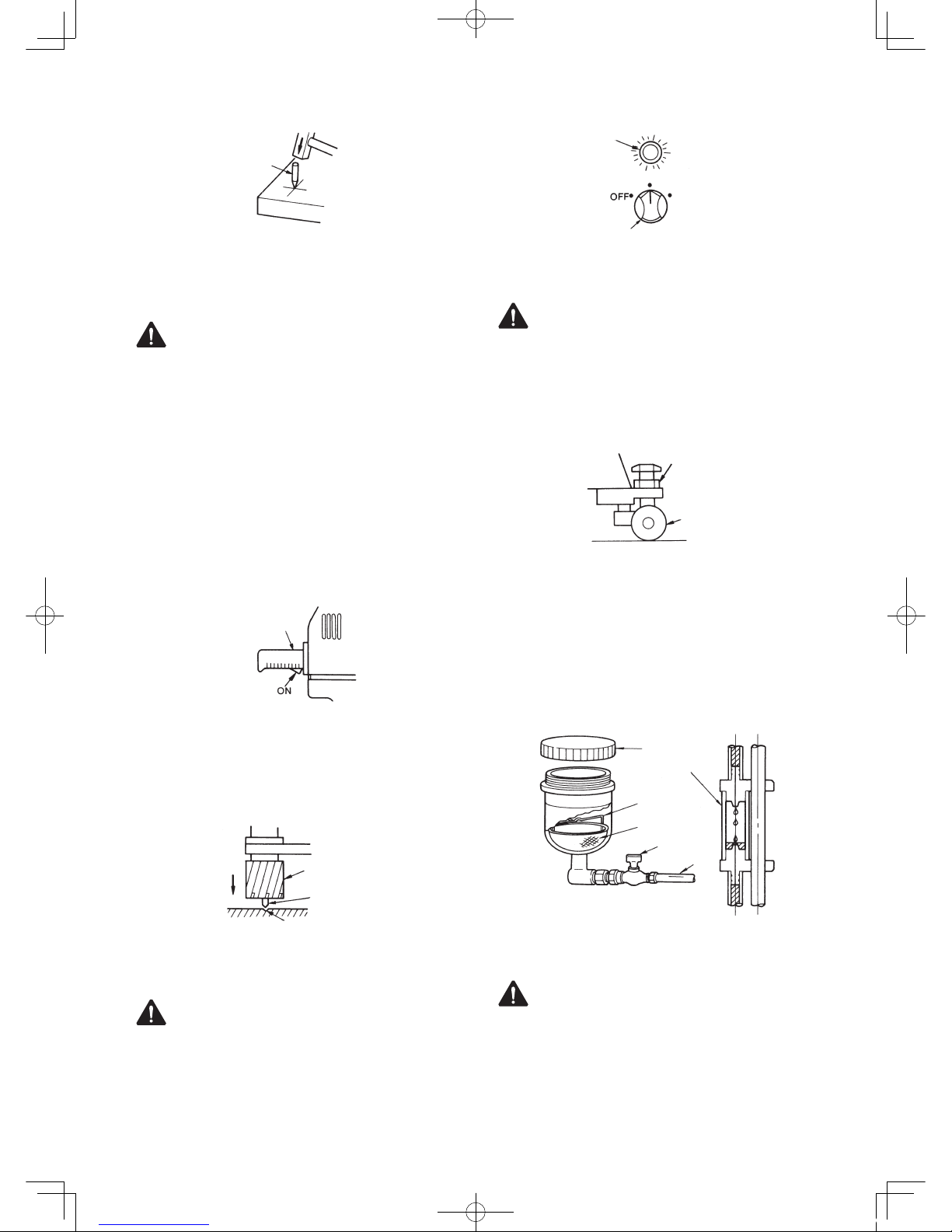
11
punch
Fig. 19
(2) Keep the Magnet and Workpiece Contacting
Surfaces Clean.
WARNING
●
Always keep surfaces clean.
Always keep the Magnet surface clean. Always
keep the work piece surface clean. If there are any
foreign objects between the Magnet and the work
piece surfaces, this will reduce magnetic power.
This could cause the machine to move during
operation. This can result in an accident. Keep
all surfaces clean of rust, chips or other foreign
material.
(3) Trigger Switch of the Electric Drill ON
Turn on the Electric Drill. Turning on the Trigger
Switch alone would not start the Electric Drill.
Electric Drill
Fig. 20
(4) Align with Punch Mark
Turn the feed handle counterclockwise to slightly
lower the JETBROACH and align the tip of Pilot
Pin to the punch mark.
Punch Mark
JETBROACH
Pilot Pin
Slightly lower
Fig. 21
(5) Magnet ON
WARNING
● Check to see that Magnetic power is activated.
Turn on the Magnet. The Main Dial Switch Lamp
will glow and magnetic power will come on.
Lamp
Drill Motor
Magnet
Fig. 22
(6) Set the Stabilizer properly
WARNING
The Stabilizer serves as the effective counterbalance
to the adhesive force of the Magnet. After switching
on the Magnet, adjust it so that the Magnet clings
to the work piece evenly without a gap. Make sure
the Stabilizer Wheels are not protruding and lifting
the Magnet off the plate.
Stabilizer
Nut
Fig. 23
(7) Cutting Oil Flow Adjustment
When the plug valve to the Oil Cup is open and the
Electric Drill is lowered by turning the Feed Handle
counterclockwise, the Pilot Pin will be pushed up
allowing Cutting Oil to begin to flow. See the oil
flow in the Oil Dropper tube and adjust the oil flow
with the Plug Valve.
Plug Valve
Tube
Oil Cup
Cap
Oil Cleaner
Oil Dropper
Fig. 24
(8) Drill Motor ON
WARNING
●
Don’t touch revolving parts.
Press the Drill Motor ON Switch to start the Drill
Motor
●
Don’t press the Rod Handle strongly or the
Magnet may lift, causing the main body to
swing.
A-100E.indd 11 12.11.28 2:26:11 PM

12
Turning the Main Dial Switch to “Drill Motor ON”
position will let the Electric Drill start running.
Drill Motor
Magnet
Fig. 25
(9) Drilling
To s t a r t d r i l li n g , t ur n t h e F e e d H a n d l e
counterclockwise. Be sure to turn the Feed Handle
slowly for the first 2~3mm depth cutting.
Feed slowly for
2~3mm
Fig. 26
When drilling a hole in an angle, channel or H-section
irons, etc., JETBROACH may be damaged when it
comes to a slanted part of the work on the final cutting
stage. Feed slowly when start and finish cutting.
Slanted part
Fig. 27
(10) Finishing the hole cutting
WARNING
● Be careful about chips.
● Do not touch the slug.
● Do not use your hands to remove chips.
When drilling is finished, raise the Electric Drill and
set the Main Dial Switch back to the “Magnet ON”
and “Motor OFF” position. When the Electric Drill has
stopped, then quickly pull the Main Dial Switch back
to the “Power OFF” position. If you fail to do this, the
Magnet will remain activated, which will shorten its life
Drill Motor
Magnet
Fig. 28
(11) Removing Slug
Don’t proceed to the next operation without
removing the slug from the operation just finished.
At the end of drilling operation slug will pop out
automatically ejected by the spring-operated Pilot
Pin. Should a slug left in the hold sticking, remove
it from the hole by tapping the collar of the slug
with a needle stick or something. (fig.29)
Cutter
Pilot pin
Slug (chips) Needle pin Slug
Fig. 29
6-3. Drilling Oblong Hole
CAUTION
Always drill oblong hole slowly.
Drill oblong hole in the order of ①, ②, ③. For the
steps ②and ③, take care so that the cutter may
not be fed into the workpiece with too much force.
Spacing between each step of drilling operations
should be so arranged that the Pilot Pin will always
hit the material yet to be machined. (fig.30)
File away any excesses
Fig. 30
6-4. Drilling Stacked Plates
CAUTION
●
Remove slug as each plated is finished:
otherwise, being blocked by the slug left
unremoved, the cutter cannot cut into the next
layer of plate, which results in the Magnet base
being pushed up possibly causing accident.
●
For stacked plates drilling, always feed and
drill slowly and carefully.
●
Before drilling stacked plates, securely clamp
the plates together in place.
●
When drilling stacked plates, retract the cutter
as each layer of plate is finished in order to
remove slug from the drilling area, then put
another hole in the next layer of plate.
A-100E.indd 12 12.11.28 2:26:12 PM

13
7 TROUBLESHOOTING
WARNING
●Never attempt to repair machine yourself: injury or damage to equipment may result.
●Please feel free to consult the sales agent through which you have purchase your machine or an
authorized dealer, when the following symptoms appear or when you have any questions about our
products.
Problem Causes Solutions
Switch lamp doesn’t come on
when Magnet Switch is turned
on.
Power supply plug is not connected to
socket.
Connect power plug to socket.
Drill Motor stops during drilling.
(Magnet is not working with
Magnet lamp not illuminating.)
Power failure has occurred or power
supply plug is disconnected.
After power failure is restored or power
supply plug is re-connected, turn on
Motor Switch again.
Magnet does not adsorb. Magnet is disconnected. Request for repair.
Drill Motor doesn't start when
Motor Switch is turned on.
Switch is broken. Request for repair.
Lateral shifting of Magnet is
detected by lateral position
sensor, bringing machine to a
compete stop.
Workpiece too thin. Use back-up plate: thickness 10 mm
(13/32”) or more.
Chips under Magnet base. Clean it up.
Worn cutting edge. Regrind or replace with new one.
Effective magnetic force too weak. Request for repair.
A-100E.indd 13 12.11.28 2:26:13 PM

14
8 MAINTENANCE/SERVICE
WARNING
●Always disconnect the power and turn off the
switch before attempting any maintenance.
Failure to disconnect the power and turn off the
switch during set up, inspection or maintenance
can cause accidents and severe injuries.
8-1. Tighten Set Screw When Machine is Not Used
For the purpose of safety, when you don’t use the
machine temporally or on a long-term basis, raise the
Drill Motor and set it in position with the Set Screw
so that it will not come down on its own weight. If
you leave the machine alone with the Drill Motor in a
lowered position, the Pilot Pin and/or cutter may be
damaged when the machine is relocated.
Before tightening the Set Screw, make sure that the
slide section in the Gearbox is properly aligned to
the head of the Set Screw.
8-2. Grease the Sliding Surfaces from Time to Time
Grease the machine body and Slide Board from time
to time.
8-3. Gearbox Clearance Adjustment
Excessive clearance between the machine body
and Gearbox would deteriorate not only drilling
performance but also cutting tool life to a substantial
degree. If you find excessive clearance, make
adjustment by tightening 5 Slide Board Adjusting
Screws on the side of the machine using the same
torque all round so that Drill Motor will not come
down on its own weight.
8-4. Keep the Tip of Pilot Pin Sharp
When the tip of Pilot Pin gets dull, it sometimes fails
to seat into punched hole, causing drilling accuracy to
deteriorate. See that the tip is sharp from time to time.
If you find it too dull, regrind or replace as required.
When regrinding do so carefully, for grinding with too
much force may cause the tip to get dull or soften
the material to such a degree that it is no longer
usable. (Fig.31)
Pilot Pin
Sharpen
the tip
Optimal angle
Fig. 31
8-5. Recovery Measures When Pilot Pin Gets
Jammed
When you change cutting tool you also change
Pilot Pin, which acts as a guide for the cutting tool.
However there are times when the pin does not
come off easy with cutting chips in the clearance
between the cutting tool and pin, causing jamming.
In such case, tap the tip of Pilot Pin with wooden
hammer, etc., pull it off. (Fig.32)
Cutter
Pilot Pin
Cutting chips
Fig. 32
8-6. Cutter Regrinding
When you need to regrind cutter, please contact
sales agent through which you have purchased your
machine or an authorized dealer near you.
Inner cutter
Outer cutter
Inner
cutter
Outer
cutter
Inner
cutter
Outer
cutter
Fig. 33
8-7. Carbon Brushes Inspection and Replacement
Check Carbon Brushes for wear periodically.
When the length of Carbon Brushes gets as short
as 6mm, replace it with a new one, for, if you don’t,
chances are that you’ll have a rectification problem
which may cause machine failure. (Fig.34)
Check – machine failure.
(1) Remove the Brush Cap with a straight slot
screwdriver.
(2) Remove the worn-out Carbon Brush and replace
it with a new one. Then reattach the Brush Cap.
(3) After replacing the Brush, operate the unit for
about ten minutes with no load.
A-100E.indd 14 12.11.28 2:26:13 PM

15
5mm
Fig. 34
9 OPTIONAL PARTS
9-1. Nitto-Brand Cutting Oil
CAUTION
Use Nitto-brand Cutting Oil for Atra Ace.
Part No. Part Name
TB01507 Cutting Oil 2ℓ (Light Blue)
9-2. Chane Ass’y
Part No. Part Name
TA99027 Chane Ass’y
9-3. Cutter
Part No Part Name Part No Part Name
TJ17709 50x75L TJ16676 76x75L
TJ16651 51x75L TJ16677 77x75L
TJ16652 52x75L TJ16678 78x75L
TJ16653 53x75L TJ16679 79x75L
TJ16654 54x75L TJ16680 80x75L
TJ16655 55x75L TJ16681 81x75L
TJ16656 56x75L TJ16682 82x75L
TJ16657 57x75L TJ16683 83x75L
TJ16658 58x75L TJ16684 84x75L
TJ16659 59x75L TJ16685 85x75L
TJ16660 60x75L TJ16686 86x75L
TJ16661 61x75L TJ16687 87x75L
TJ16662 62x75L TJ16688 88x75L
TJ16663 63x75L TJ16689 89x75L
TJ16664 64x75L TJ16690 90x75L
TJ16665 65x75L TJ16691 91x75L
TJ16666 66x75L TJ16692 92x75L
TJ16667 67x75L TJ16693 93x75L
TJ16668 68x75L TJ16694 94x75L
TJ16669 69x75L TJ16695 95x75L
TJ16670 70x75L TJ16696 96x75L
TJ16671 71x75L TJ16697 97x75L
TJ16672 72x75L TJ16698 98x75L
TJ16673 73x75L TJ16699 99x75L
TJ16674 74x75L TJ16700 100x75L
TJ16675 75x75L
A-100E.indd 15 12.11.28 2:26:14 PM

16
1
2
3
4
5
6
7
8
9
9
10
11
12
13
14
15
16
88
89
90
91
87
17
18
19
20
21
14
22
23
24
25
26
27
28
29
30
31
32
37 38
39
39
73
40
41
42
43
44
45
46
86
47
35
48
49
54
55
50
51
52
35
51
51
53
56
54
51
57 58
59
56
35
61
63
35
64
65
66
67
68
68
69
70
71
72
74
75
76
77
78
79
80
81
82
83
84
84
85
82
13
92
93
94
95
96
97
98
60
33
133
35
134
36
62
10 Exploded Diagram: Machine
WARNING
This diagram is for reference only. Do not attempt service or repair the Nitto Portable Magnetic Drilling Machine. Do not take the machine apart. Contact an authorized
Nitto dealer for all service and repair of the machine. Improper service and repair can cause accidents and severe injuries. Never attempt to modify the machine. Never
attempt to service or repair the machine youself.
A-100E.indd 16 12.11.28 2:26:24 PM

17
No. Part No. Part Name Q'ty Price
1 TA9A686 Arbor Body Ass'y 1set
2 (TP17596) Arbor Body 1
3 (TP17597) Hex.Socket Set Screw 16x9 2
4 (TP16720) Spring 1.6x11x177 1
5 (TP16721) Pilot Spacer 1
6 (TP16722) Spacer 16x31.8x12 1
7 (TP07623) Internal Retaining Ring C-32 2
8 TA9A193 Oil Ring Ass'y 1set
9 (TP14499) Oil Seal GD38x48x4 2
10 (TP14964) Oil Ring 1
11 (LP10496) Hex.Nut M6 1
12 (TP05469) Hex.Socket Head Cap Screw
6x45 1
13 (TP14500) Hose Nipple 2
14 TP12773 Washer 38.5x54x1 2
15 TB00732 Bush 1
16 TP16725 Bracket 1
17 TB00564 Electric Drill Ass'y 1set
− (TA9A388) Brush Ass'y 1set
− (TB00953) Armature Ass'y 1set
18 TP15637 Hex.Head Bolt 16x40 1
19 TP15638 Spring Washer M16 1
20 TP00802 Washer M16 1
21 TP14969 External Retaining Ring
ISTW-38 1
22 TA9A527 Slide Board 1
23 TP05882 Hex.Socket Head Cap Screw
5x35 5
24 TP06141 Hex.Socket Set Screw 6x6 1
25 TP02862 Hex.Socket Head Cap Screw
5x15 6
26 TP08584 Hex.Nut M8 3
27 TP04531 Hex.Head Bolt 8x30 2
28 TP16284 Hex.Socket Head Cap Screw
8x45 2
29 TP02260 Hex.Socket Head Cap Screw
8x35 1
30 TP03261 Spring Pin 4x26 1
31 TP02575 Cap 1
32 TP02638 Pan Head Screw 4x12 4
33 TB09296 Lamp Holder Ass'y 1set
35 TP02618 Pan Head Screw 4x8 24
36 TP16737 Lamp Holder Plate 1
37 TP17636 Stopper Plate 1
38 TP01644 Hex.Socket Head Cap Screw
6x12 3
39 TP02936 Hex.Nut M5 7
No. Part No. Part Name Q'ty Price
40 TP00021 Hex.Socket Head Cap Screw
5x10 1
41 TP02937 Hex.Socket Set Screw With
Cup Point 5x20 6
42 TP02931 Set Screw 1
43 TP02578 Retaining Ring CE-22 1
44 TP02571 Pinion Shaft 1
45 TP09853 Spring Pin 5x34 1
46 TP02572 Handle Boss 1
47 TP16738 Spacer 4
48 TB09202 Spare Laod Detecting Device
Sub Ass'y 1set
49 TP00067 Hex.Head Nut M3 2
50 TP15957 Sensor Transformer 1
51 TP00056 Pan Head Screw 3x6 10
52 TP16740 Laod Detecting Device Board 1
53 TP16741 Holder 4
54 TP02639 Hex.Nut M4 5
55 TQ10920 Solid Relay G3NA220B DC5-24 1
56 TP16739 Transfomer 2H2403 1
57 TB01396 Print Board Ass'y 1set
58 TP14698 Cable Connector 2
59 TA97849 Cabtyre Cable Ass'y (1.25 3-core) 1set
60 TQ01511 Spacer 2
61 LP08489 Binding Head Screw 4X6 1
62 TB07298 Lamp Holder Ass'y 1set
63 TP12781 Knob MY-30 1
64 TQ00776 Switch Plate 1
65 TP12780 Rotary Switch 1
66 TP13813 Spring Pin 5x30 1
67 TB00006 Square Magnet Sub Ass'y 1set
68 TP00045 Hex.Socket Head Cap Screw
8x25 6
69 TP16717 Pole Plate 1
70 TP01460 Hex.Socket Head Cap Screw
8x20 4
71 TA94059 Stabilizier Ass'y 1set
72 TP16724 Dust Cover 1
73 TP04519 Hex.Socket Set Screw With
Dog Point 5x18 4
74 TB01180 Body Sub Ass'y 1set
75 TP13832 Slide Plate 2
76 TP16735 Rack 1
77 TP06526 Spur Gear B 1
78 TP02567 Gear Shaft 2
79 TP02570 Retaining Ring E-140 2
80 TP06525 Spur Gear A 1
No. Part No. Part Name Q'ty Price
81 TA99688 Oil Dropper Ass'y 1set
82 (TP15965) Tube 4X7X190 1
83 (TA9A390) Oil Dropper Sub Ass'y 1set
84 (TP15964) Tube 4X7X150 1
85 TP15156 Oil Ring Stopper 1
133 TQ13777 Spacer 16x20x4 1
134 TQ13776 Lamp Holder Cover 1
ACCESSORIES
No. Part No. Part Name Q'ty Price
86 TP00118 Feed Handle 3
87 TA9A207 Pilot 12075 Ass'y 1set
88 (TP06158) Hex. Screw 8x8 1
89 (TJ16748) Pilot 12075A 1
90 (TP16750) Spring 1x5.3x120 1
91 (TP16749) Pilot 12075B 1
− TA98903 Oil Cup Ass'y 1set
92 (CP21947) Seal Packing 1
93 (TP14495) Two-Port Cock 1
94 (TP11916) Cover 1
95 (TP15823) Oil Cleaner 1
96 (TA98909) Oil Cup Sub Ass'y 1set
97 (TP14497) Cup Holder 1
98 (TP16193) +Screw 5x15 1
TP13892 Hex. Socket Screw Key 2 1
TP04305 Hex. Socket Screw Key 2.5 1
TP04696 Hex. Socket Screw Key 3 1
TP01939 Hex. Socket Screw Key 4 1
TP04004 Hex. Socket Screw Key 5 1
TP00170 Hex. Socket Screw Key 6 1
TP03249 Hex. Socket Screw Key 8 1
TP14091 Spanner 7X8 1
TQ07167 Tool Box 285X140X70 1
TA99027 Safty Chain Ass'y 1set
TB02145 Soluble Cutting Oil 0.5 Ass'y 1set
TQ12569 Instruction Manual 1
The part numbers with ( ) are include in the Ass'y part
wrriten above them.
A-100E.indd 17 12.11.28 2:26:25 PM

A-100E.indd 18 12.11.28 2:26:26 PM

Printed in JAPAN
TQ12569-2
READ ALL INSTRUCTIONS BEFORE OPERATING THIS TOOL
ATRA ACE Model A-100
PROFESSIONAL TOOL
Overseas Affiliates / Offices
NITTO KOHKI U.S.A., INC.
46 Chancellor Drive, Roselle, IL 60172 U.S.A.
Tel: (1)-630-924-9393 Fax:(1)-630-924-0303
NITTO KOHKI EUROPE CO., LTD.
Unit 21, The Empire Centre Imperial Way,
Watford Herts, WD24 4TS, U.K.
Tel: (44)-1-923-239668 Fax:(44)-1-923-248815
NITTO KOHKI DEUTSCHLAND GMBH
Lerchenstr.47 D-71144 Steinenbronn, Germany
Tel: (49)-7-157-22436 Fax:(49)-7-157-22437
NITTO KOHKI CO., LTD., SINGAPORE BRANCH
10 UBI CRESCENT #01-62,
UBI TECHPARK LOBBY D, SINGAPORE 408564,
Tel: (65)-6227-5360 Fax:(65)-6227-0192
NITTO KOHKI CO., LTD.,
BANGKOK REPRESENTATIVE OFFICE
M&A Business Center 38Q. House Convent Bldg.,
7th Floor, Unit 7A, Convent Rd., Silom, Bangrak,
Bangkok 10500 Thailand
Tel: (66)-2-632-0307 Fax:(66)-2-632-0308
NITTO KOHKI AUSTRALIA PTY. LTD.
77 Brandl St., Brisbane Technology Park,
Eight Mile Plains QLD 4113 Australia
Tel: (61)-7-3340-4600 Fax:(61)-7-3340-4640
NITTO KOHKI (SHANGHAI) CO., LTD.
Room1506, suite C, Orient International Plaza,
NO85 LouShanGuan Road,Shanghai, 200336, CHINA
Tel: (86)-21-6415-3935 Fax:(86)-21-6472-6957
NITTO KOHKI CO., LTD.,
SHENZHEN REPRESENTATIVE OFFICE
Rm.#0726, 7F International Culture Bldg., 3039, Shennan
Zhong Rd., Futian District, Shenzhen, China Post Code:518033
Tel: (86)-755-8375-2185 Fax:(86)-755-8375-2187
A-100E.indd 19 12.11.28 2:26:26 PM
Table of contents
Other Nitto Drill manuals


Popular Drill manuals by other brands

Worx
Worx WXI 60 Safety and operating manual

Ingersoll-Rand
Ingersoll-Rand IR17JV Operation and maintenance

Cornwell Tools
Cornwell Tools CAT350HD operating instructions

Cleco
Cleco 5 Series Operation & service manual

Hitachi
Hitachi FDV16VB - 5/8" Reversible Hammer Drill Disassembly & reassembly procedures

Neilsen
Neilsen CT3142 manual


