Nitto ATRA ACE WA-3500 User manual
ehT specifications and configurations contained in this document are subject to
change without prior notice due to improvements we are making day in, day out.
Manufactured by :
NITTO KOHKI Co., Ltd.
2-9-4, Nakaikegami, Ohta-ku,
Tokyo, 146-8555, Japan
Tel : (81)-3-3755-1111
Fax : (81)-3-3753-8791
E-mail : overseas@nitto-kohki.co.jp
URL : www.nitto-kohki.co.jp
Keep the manual handy – so you can use it whenever necessary.
PORTABLE MAGNETIC DRILLING MACHINE
Read this manual carefully before operating your Nitto Kohki
Portable Magnetic Drilling Machine. Keep this manual with
your machine. All users of the Nitto Kohki Portable Magnetic
Drilling Machine must read this manual.
ATRA ACE Model WA-3500
Professional Tool For One-Touch Type Annular Cutter Only
(Side-Lock Type Annular Cutter cannot be used.)
Specifications
Model WA-3500
Power Supply (Single Phase) 220-240 V 〜50/60 Hz
Drill Motor
Rated Power Consumption 1100 W
Rated Current 5.1 A
No-load Speed 950 min-1
Load Speed 580 min-1
Magnet Power Consumption 34 W
Hole Capacity
JETBROACH One-touch type φ17.5 〜φ 35mm
Plate thickness 35mm(50mm)
HI-BROACH One-touch type φ14 〜φ 35mm
Plate thickness 25mm(50mm)
Magnet Holding Power 7,056N
Magnet Dimensions 92mm ×213mm
Weight 20kg
Short-Circuit Current Rating 5kA
Original Instructions
TQ12846-6
1
Thank you very much for your purchase of Nitto
Kohki product.
Before using your machine, please read this
manual carefully so that you may use it properly
to get the most out of it.
Please keep the manual handy - so you can
use it whenever necessary.
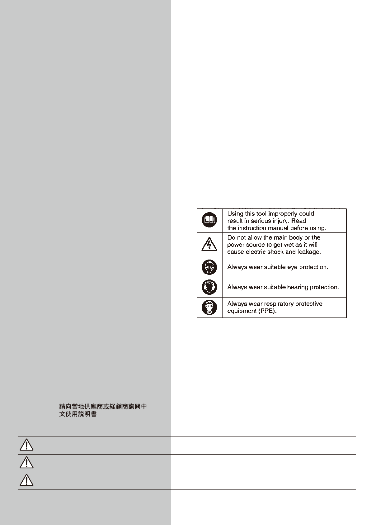
・English :Please ask your dealer or
distributor for instruction manual
in local language(s).
・German :Bitte fragen Sie lhren Händler
nach eine Betriebsanleitung in
Landessprache.
・French :S'il vous plait, veuillez demandez
á votre foumisseur de manuel
instruction en langue locale.
・Spanish :Por favor, cantacte con su
distribuidor para el manual de
instrucciones en español.
・Portuguese :Por favor pessa ao seo agente
ou distribuidor o manual de
instrucces ih linguagen local.
・Italian :Per Manuale lstruzioni in lingua
locale Vi preghiamo di rivolgervi
al rivenditore o distributore.
・Dutch :Vraag uw handelaar
om een nederladstalige
gebruiksaanwijzing.
・Swedish :Be er lokala Åtreförsäljare eller
distributör om manualer pá
svenska.
・Danish :Venligst henvend Dem til den
danske distributør for instructions
manualer.
・Polish :Prosze pytac swojego dealera
lub dystrybutora o instrukcje
obslugi w jezyku localnym.
・中文 :
CONTENTS
GENERAL SAFETY RULES ………………………………… 2
POWER TOOL SAFETY……………………………………… 3
ABOUT YOUR NITTO PORTABLE MAGNETIC
DRILLING MACHINE ………………………………………… 4
1. APPLICATION …………………………………………… 7
2. RECEIVING INSPECTION ……………………………… 7
3. PART NAME ……………………………………………… 8
4. FUNCTIONS OF ELECTRONIC CONTROL ………… 9
5. MACHINE SETUP ……………………………………… 9
6. MACHINE OPERATION ……………………………… 11
7. TROUBLESHOOTING………………………………… 14
8. MAINTENANCE/SERVICE…………………………… 15
9. OPTIONAL PARTS …………………………………… 16
PICTOGRAM
・Sound Pressure Level :Maximum 85dB(A) according
to Clause 1.7.4(f), Annex I,
Machinery Directive.
・Sound Power Level :Maximum 98dB(A)
・Operating Temperature :5˚C 〜40˚C
・Operating Humidity :Maximum 90% at 25˚C
・Over-voltage Category :Category Ⅱaccording to
IEC664-1
・Pollution Degree :Degree 3 according to IEC664-1
・Wiring Diagram No. :TZW0055
The following Safety notations are used throughout the manual to highlight safety precautions for the user and for the machine.
DANGER: Indicates an imminently hazardous situation which, if not avoided by following the
instructions given, will result in death or serious injury.
WARNING: Indicates a potentially hazardous situation which, if not avoided by following the
instructions given, could result in death or serious injury.
CAUTION: Indicates a potentially hazardous situation which, if not avoided by following the
instructions given, could result in injury or material damage.
Caution: Important precautions for machine or tool setup, operation and maintenance.

2
WARNING
Some dust created by power sanding, sawing,
grinding, drilling and other construction activities
contains chemicals known [to the State of California]
to cause cancer, birth defects or other reproductive
harm. Some examples of these chemicals are;
・Lead from lead-based paints.
・
Crystalline silica from bricks and cement and
other masonry products.
・
Arsenic and chromium from chemically-treated
lumber.
Your risk from these exposures varies, depending on
how often you do this type of work. To reduce your
exposure to these chemicals; work in a well ventilated
area, and work within approved safety equipment,
such as those dust masks that are specially designed
to filter out microscopic particles.
GENERAL SAFETY RULES
TO OPERATORS
Always Wear Proper Clothing
●Do not wear loose clothing. Loose clothing can
become caught in the drilling machine. This could
cause severe injuries. Be careful that loose clothing
does not come into contact with the machine.
●Wear non-skid footwear. If you lose your footing,
you could contact moving portions of the machine.
This could cause severe injuries. Always wear non-
skid footwear and remain balanced when using the
drilling machine.
●Be careful of long hair. Wear a hat or a hair net to
contain long hair. Long hair can become caught in
the drilling machine. This will cause severe injuries.
Be careful that long hair does not come into contact
with the drilling machine.
Always Wear Suitable eyeprotection
●Always wear Suitable eyeprotection. The operation
of your drilling machine will cause flying chips and
particles. These will cause severe eye injuries. You
must always wear Suitable eyeprotection.
●Not all glasses are Suitable eyeprotection. Wear
only Suitable eyeprotection that comply with ANSI
standards. Not all of the lenses are shock resistant.
Ordinary glasses will not provide sufficient eye
protection.
Always Wear Suitable Hearing Protection
●Always wear Suitable hearing protection. The
operation of your drilling machine will cause big sound
occurs. These will cause severe hearing loss injuries.
You must always wear Suitable hearing protection.
Wear respiratory protective equipment (PPE)
●Wear respiratory protective equipment (PPE) when
working in an environment where dust particles are
generated in operation.
Maintain Good Posture
●Always wear non-skid footwear and maintain good
posture. Do not use the drilling machine when you
are tired. Fatigue or loss of balance could cause
you to lose control of the machine. This could cause
severe injuries. Always stay balanced. Always keep
good posture. Stop using the machine if you are
tired.
Never Touch the Cutting Tip
●Never touch the moving or cutting tip. Contact with
the moving tip will cause severe injuries. Always
keep all parts of your body away from the cutting tip.
Always keep your hand and clothing away from the
cutting tip.
ABOUT THE WORK AREA
Keep Work Area Clean
●Always keep your work area clean. Cluttered work
areas cause accidents. Always keep clear of other
objects.
●Never use the magnetic drilling machine when it is
wet. Always use the drilling machine in a dry area.
Do not use the drilling machine in the rain. If you
use the machine when it is wet you can get electric
shock. If you use the machine in the rain you can
get an electric shock.
●Always use the drilling machine in a well-lighted
area. Do not use the drilling machine in the dark.
●Avoid all flammable materials. Use of the drilling
machine may cause a spark that could ignite a fire
or an explosion. Never use the machine near any
flammable material.
●Keep away from children. Always keep the drilling
machine away from children. Do not operate drilling
machine when children are present.
BEFORE OPERATION
Make sure that all parts are free from damage
● Make sure that the drilling machine is in good
operating condition. Operation of a damaged
machine could result in severe injuries. If there
is any damage to the machine, do not use the
machine. If there is any damage to the machine,
take it to an authorized Nitto dealer for repair.
● Do not attempt service or repair of the drilling
machine. All service or repair should be done by an
authorized Nitto dealer.
Secure Your Work
● Always secure your work piece. Improperly mounted

3
work can become loose. This can cause severe
injuries. Always secure all work.
●Always use a vice or a clamp. Do not attempt to
hold any work piece with your hand. Attempting to
hold a work piece with your hand may cause severe
injuries. Always use a vice or clamp to hold the work
piece.
●Always secure your drilling machine. Improperly
mounted drilling machine can come loose. This can
cause severe injuries. Always secure the drilling
machine.
Avoid Clutter
●Always stay clear of other objects. Cluttered work
areas cause accidents. Always keep a clean work
area and stay away from other objects.
Always Remove S panner W renches and
Adjustment Tools
●Always remove spanner wrenches and adjustment
tools after adjustments have been made to the
drilling machine. Always remove all adjustment tools
before using the drilling machine.
Always Use a Cutter that is Appropriate for Your
Work
●Always use a cutter that is appropriate for your
work. Avoid heavy-duty work that is the beyond the
capacity of your drilling machine. If the work exceeds
the capacity of your drilling machine, this can cause
accidents and severe injuries. Always use the
drilling machine in accordance with its performance
specifications.
SAFE HANDLING
●Never leave the magnetic drilling machine
unattended while it is running. When the machine
is unattended, disconnect the power source. Do
not leave the work area until the machine comes to
a complete stop. Operating the machine while it is
unattended can case accidents that may result in
severe injuries.
HOW TO STORE YOUR MAGNETIC DRILLING
MACHINE
●Always store the machine in a dry area.
●Always keep the machine out of the reach of
children.
HOW TO CARRY YOUR MAGNETIC DRILLING
MACHINE
●Disconnect the power and turn off the machine
whenever you carry the machine.
MAINTENANCE
Do not take apart or modify your magnetic drilling
machine.
●Do not attempt to disassemble or modify your
magnetic drilling machine.
●Do not modify your magnetic drilling machine.
Modifications can cause accident and severe
injuries.
●All service and repairs must be performed by an
authorized Nitto dealer. Any attempt to service or
repair the machine yourself may result in an accident
and severe injuries.
Check all Parts for Damage.
●Always inspect the magnetic drilling machine before
use.
●Always check that the pilot pin and cutter are in
good condition. Use of the machine with worn pilot
pins or worn cutter can cause accidents and severe
injuries.
●Inspect all cutter before you put them on the
magnetic drilling machine.
●Do not operate the magnetic drilling machine with a
damaged or worn cutter. Do not operate the machine
with a damaged or worn pilot pin. Do not operate the
machine with any damaged accessory. Operating
the machine with any damaged part or accessory
can cause accidents and severe injuries. If there is
any damage to the magnetic drilling machine do not
operate the machine. Take it to an authorized Nitto
Dealer for repair.
●Always have the magnetic drilling machine repaired
at an authorized Nitto dealer. Always take the
magnetic drilling machine to an authorized Nitto
dealer for service, repair and replacement parts. If
you cannot locate an authorized Nitto dealer near
you, please contact your sales representative.
●Always use Nitto genuine parts. The use of improper
or non-Nitto parts can cause accidents and severe
injuries. Never use unauthorized parts. To obtain
genuine Nitto parts, contact your sales agent.
●Do not remove any nameplate from your magnetic
drilling machine. Do not remove any labels from
your magnetic drilling machine. If any label or
nameplate is damaged contact your sales agent for
a replacement.
POWER TOOL SAFETY
WARNING
● Always make sure that the machine is properly
grounded. If the machine is not properly grounded,
someone can get an electric shock.
●If you have any doubt about the grounding of
the magnetic drilling machine, contact a licensed
electrician.
●Never connect the grounding conductor to a gas
4
pipe. This will result in an explosion and severe
injuries or death.
●Always check the grounding conductor. If you have
any doubts about the grounding conductor contact a
licensed electrician.
●Wiring connections to a grounding rod require the
expertise of a licensed electrician. Do not attempt
the wire connections yourself. Always contact a
licensed electrician.
●Do not abuse the power cord. A damaged power
cord can cause an electrocution. A damaged power
cord can cause fires. Always inspect the cord. If the
cord is damaged, do not use the magnetic drilling
machine.
●Do not carry the machine by the cord. Do not pull
the cord to disconnect it from a socket.
●The cord can become damaged from heat, contact
with sharp objects or from being twisted. Always
inspect the cord. Do not use the machine if the cord
is damaged.
●Always use a ground fault circuit interrupter. The use
of a ground fault circuit interrupter may be required
by government regulations. The failure to use a
ground fault circuit interrupter may result in electric
shock.
●Avoid starting the magnetic drilling machine abruptly
or unintentionally.
●Always make sure that the switch is turned off before
connecting the power source.
●Always disconnect the power source and turn off
the switch before setting up for work operations.
Always disconnect the power and turn off the
switch when inspecting work. Always disconnect
the power and turn off the switch before attempting
any maintenance. Failure to disconnect the power
and turn off the switch during set up, inspection
or maintenance can cause accidents and severe
injuries.
ABOUT YOUR NITTO PORTABLE MAGNETIC
DRILLING MACHINE
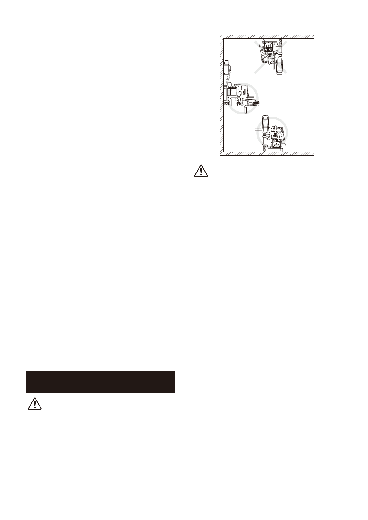
DANGER
Do not use your portable drilling machine on the
ceiling.
●Use of the portable drilling machine on the ceiling
is dangerous. The machine could fall. The falling
machine could cause severe injuries or death. (Fig.1)
Fig. 1
WARNING
Do not use the Magnet for more than five hours.
●More than five hours of uninterrupted operation may
cause a fire. Five hours of uninterrupted operation
generates extreme heat in the Magnet. This heat
can cause a fire. Do not touch the Magnet. When
the Magnet is hot, touching it will cause a severe
burn injury. Never use the Magnet for more than
five continuous hours. When you are not using the
Magnet, turn the switch to the "OFF” position and
pull the plug out of the power source.
Do not use the Drill Motor for over 30 minutes.
●Uninterrupted operation of the Drill Motor for over 30
minutes generates heat. This heat can cause a fire.
Never use the Drill Motor for over 30 minutes. When
you are not using the Drill Motor, turn the switch to
the "OFF' position and pull the plug from the power
source.
Use only on magnetic materials.
●Your portable drilling machine cannot be used
on non-magnetic materials, such as aluminum,
stainless steel, copper or alloys. The Magnet will not
work on non-magnetic materials. Attempting to use
the Magnet on non-magnetic materials could cause
an accident.
Use caution during wall operation.
●When using your portable magnetic drilling machine
on a magnetic wall, always use caution.
●Never stand under the machine.
* Never allow anyone to stand under the machine.
* Never put any part of your body under the
machine.
* If the machine falls, it could result in severe injury
or death.
●Always remove cutting oil from the tank before using
the machine on a wall. You must manually apply
cutting oil to the cutting tool.
5
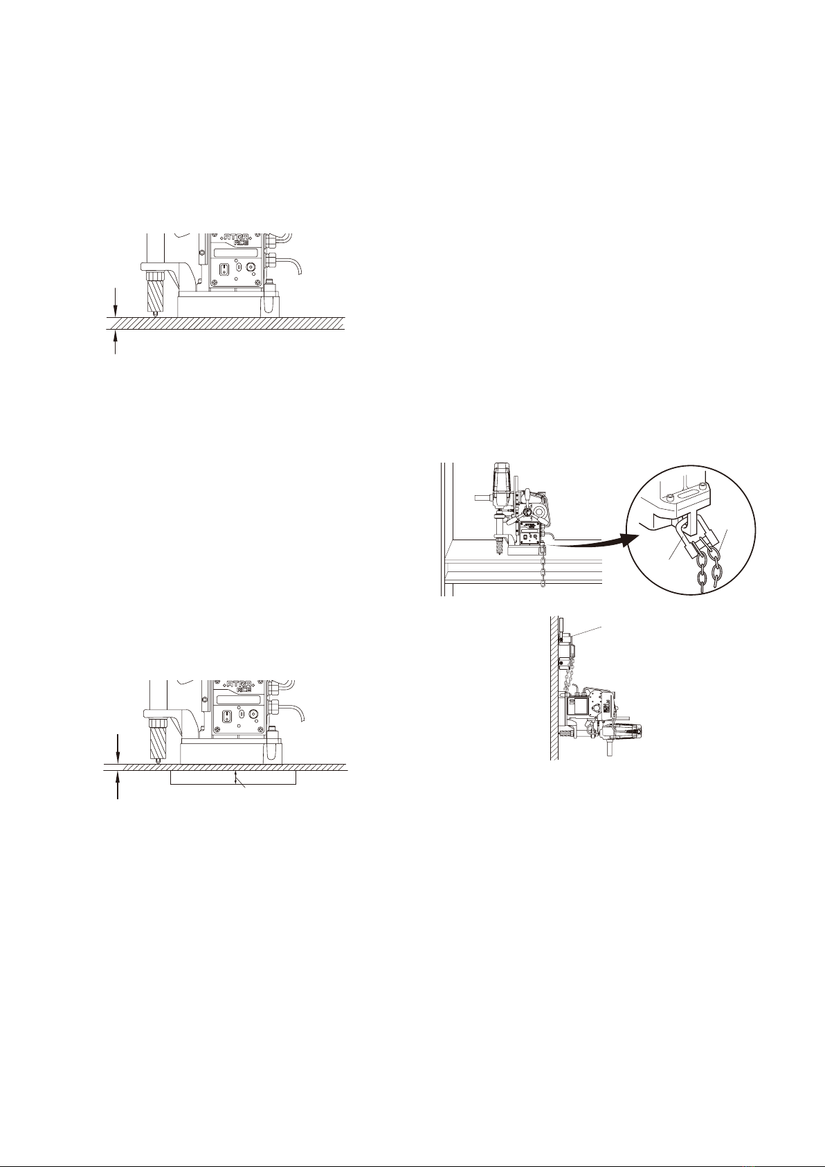
Always use a work piece that is at least 3/8” (9
mm) thick.
●The work piece must be at least 3/8” (9 mm) thick. If
a work piece is too thin, the magnetic power of your
machine will decrease. This will cause the machine
to move during operation. This could result in an
accident. (Fig.3)
Not less than 3/8" (9mm)
Fig. 3
Use an iron back-up plate.
●If the work piece is less than 3/8” (9 mm) thick, you
must use an iron back-up plate that is more than
13/32”(10 mm ) in thickness. The surface area of the
iron back-up plate must he greater than the surface
area of the Magnet. An appropriate back-up plate is
necessary to boost the holding power of the Magnet.
(Fig.3)
Use of an inappropriate back-up plate can result in
an accident, If the back-up plate is not thick enough
or big enough, the machine will come loose during
operation. This can result in an accident and severe
injuries.
Less than 3/8" (9mm)
Plate 13/32" (10mm) or
more thick piece iron
Fig. 3
Always keep surfaces clean.
●Always keep the Magnet surface clean. Always keep
the work piece surface clean. If there are any foreign
objects between the Magnet and the work piece
surfaces, this will reduce magnetic power. This could
cause the machine to move during operation. This
can result in an accident. Keep all surfaces clean of
rust, chips or other foreign material.
Do not place the machine over a hole.
●Do not attempt to position the Magnet over a hole.
Attempting to straddle a hole will reduce the power
of the Magnet. This will cause the work piece to
come loose during operation and can cause an
accident.
Always use a Chain to secure the machine.
●If the machine falls, it can cause severe injuries.
There is always a possibility that magnetic power
can be lost or reduced because of a power failure.
Magnetic power can be lost on rough surfaces. You
must take precautions to prevent the machine from
falling.
●This machine comes with the Chain. The Chain is
to be used to fasten the machine to the work piece.
If you do not use the Chain, it is possible that the
machine may fall. (Fig.4)
●If use of the Chain is not possible because of the
size of the work piece, you must use another method
of securing the machine. Use a Supporting Magnet
Assʼy to prevent the machine from falling.
●The use of a Supporting Magnet Assʼy is shown
below. (Fig.5)
Fig. 4
Supporting Magnet Assy
Fig. 5
Always set the Magnet in the proper position.
●Always set the Magnet parallel to the longitudinal
direction of the material. Failure to set the Magnet in
the proper position may result in reduced magnetic
power. This can cause the machine to move in
operation. This can cause an accident resulting in
severe injuries.
●When using on H-section steel, as shown in the
figure below, set the Magnet in a direction parallel
to the longitudinal direction of the material. This will
ensure that the Magnet is in the best position for
magnetic attraction.(Fig.6)
●Poor magnetic power may result in damage to the
cutter or damage to the work piece.
Shackle
Chain

6
Fig. 6
Be careful about chips.
●Keep your hands away from the cutting area at all
times. During drilling, there will be chips. The chips
are sharp. The chips are rotating with the cutter. Any
contact with the chips can cause severe injuries.
Do not touch the slug.
●Do not touch the slug. The slug is very hot. It will
cause severe burns. Make sure that no one touches
the slug. Make sure that there is no one below the
work area during operation. Hot slugs will fall. Hot
slugs can cause severe burns, other severe injuries,
or even death. Always wear protective equipment,
including protective headgear, eye protection,
hearing protection, and gloves. Do not allow any
person without protective equipment to come near
the machine.
Do not use your hands to remove chips.
●Chips have sharp edges. Use a screwdriver to
remove chips. If you use your hands to remove
chips, you can be injured, even if you are wearing
gloves. Do not use your hands to remove chips
under any circumstances.
The cutting edge is sharp.
●The cutting edge is sharp. If you do not wear gloves,
you will be cut. Attempting to change the cutter can
result in severe injuries.
Do not use Cutting Oil for other purposes.
●Cutting Oil should be used only for drilling. Please
refer to Section 5-5 of this manual for further
warnings and instructions about Cutting Oil.
The Drill Motor will stop automatically when
drilling operation is completed. If the Drill Motor
fails to stop automatically, turn off the Motor
Switch to stop it and then contact sales agent
from which you have purchased your machine or
an authorized dealer near you for repair.
CAUTION
Do not use power that is generated by an engine-
driven welder.
●The use of an engine-driven welder as a power
source may cause your magnetic driven machine to
malfunction, Power from an engine-driven welder
can damage the electronic circuits in your portable
drilling machine.
Use a Proper extension cord.
●Do not use an extension cord that is too thin. Do
not use an extension cord that is too long. Do not
use an extension cord that is wound on a drum.
Do not share an extension cord with other motor-
driven tools. These uses can cause voltage to drop
and can reduce the holding power of the magnet,
causing the machine to move during operation. This
can decrease performance and may cause damage
to the machine. (Fig.7)
Extension Cord
Max length Size (nominal cross-section
area of the conductor)
10 m (32.8ft) Min 1.25 mm2 (AWG16)
20 m (65.6ft) Min 2 mm2(AWG14)
30 m (98.4ft) Min 3.5 mm2(AWG12)
Fig. 7
Do not use this machine on the steel material
being electrically welded.
●When the electric welder is not properly grounded,
electricity will run through the Atra Ace machine
via its Magnet, causing possible failure or
malfunctioning, which in turn may cause accident.
Do not force to feed cutter when drilling manually.
●Because the Hi-Broach and Jet-Broach have
rather thin cutting edges with less cutting pressure
resistance as compared to twist drill, do not force to
feed the cutter when drilling manually.
If you feed it with too much force, the cutter may
break or end up with shorter life than otherwise.
Always use a compatible Pilot Pin.
●The Pilot Pin must be compatible with the cutter. An
improper Pilot Pin may result in an accident. See
Section 5-3 to identify compatible Pilot Pins and
cutters. The proper Pilot Pin to be used will vary,
depending on the type of cutter, the diameter of the
cutter, and the length of the cutter.
Do not switch to auto while drilling in manual mode.
●When you want automatic drilling, set the machine

7
to auto mode first and then start drilling.
Do not switch overto auto mode in the middle of
manual drilling operation: the Drill Motor may come
to a stop if you do so.
Do not apply manual force when feeding in auto
mode.
●Do not apply force to the Rod Handle when feeding
in auto mode (with the Rod Handle pushed toward
the machine).
Do not start drilling with manual feed.
●Do not start drillingwith manualfeed.Once you
have started with manualfeed, however, you must
not change mode to automatic feed half way through
the operation because the Drill Motor may come to a
stop making it impossible to complete the hole.
Leaving the machine alone in a subzero C˚
environment for many hours may cause Drill Motor
start-up failure at the initial startup. This is nothing
unusual. Set the auto-feed switch to OFF (with
the Rod Handle pulled out toward the operator)
and run the machine idly for a few minutes. That
should take care of initial startup failure.
1. APPLICATION
Thisis a portable drillingmachine with a Magnet,
geared to drilling mild steel (or equivalent) using One-
Touch type Jet-Broach orHi-Broach.The machine
willbe mounted on the workpiece to be drilled with
the Magnet securely fasteningthe machine to the
workpiece while drilling takes place.
2. RECEIVING INSPECTION
Upon unpacking, check to see that the shipment is
complete without damage or oil leakage in transport.
Should you find any damage orshort-shipment,
please contact salesagent through which you have
purchased your machine or an authorized dealer near
you for corrective actions.
Package Contents Q ty Check
ATRA ACE 1set
Pilot Pin 08035 1
Hex. Socket Screw Key 3 1
Spanner 8X10 1
Cutting Oil 0.5ℓ
Can 1
Side Handle 1
Chain 1
Guard 1
Instruction Manual 1
8
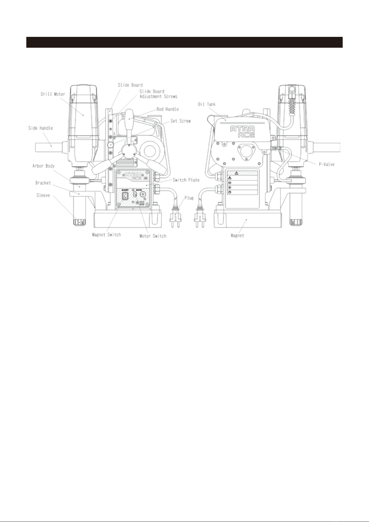
3. PART NAME
Fig. 8

9
4. FUNCTIONS OF ELECTRONIC
CONTROL
4-1. Overload Detecting Function
When overload occurs during drilling operation,
the overload detector puts the following functions
to work. Please note, however, that there may be
cases where the overload detector does not work
properly if power is drawn from an engine generator
with fluctuating output voltage, sometime tool high
and sometime too low.
●Automatic Feed Rate Control Function
Automatic drill feed starts slowly for the first few
seconds and then it picks up speed automatically to
an appropriate level in terms of cutting load applied
to the cutter. In addition, a cutter diameter factor
is also taken into account for automatic feed rate
control.
●Automatic Stop Function
Overload to the Drill Motor or feed motor
automatically stops the drill and ongoing feed,
preventing possible damage to the machine and
cutter. However, if a worn or blunt cutter is being
used, it may break.
4-2. Automatic Cycle Stop Function
When drilling operation is complete with the machine
relieved of cutting load, the Drill Motor stops
automatically.
4-3. Limit Switch Function
Even if the automatic cycle stop function fails to
operate and the drill continues to feed down, the
Limit Switch will stop the down-feed near the lower
limit of the stroke and the Drill Motor.
4-4. Lateral-Shifting Detection Function
This function stops drill feed and the Drill Motor
when lateral shifting of the Magnet is detected.
4-5. Re-Start Prevention Function
The re-start prevention function comes into play
when power failure is restored that has occurred
during operation.
Thanks to this feature, when a plug that has been
disconnected during operation is re-plugged into the
receptacle or when power failure is restored that has
occurred during operation, the Drill Motor will NOT
restart automatically preventing possible accident --
although Magnet lamp will come on and magnetic
power restored.
To resume operation, turn ON the Motor Switch on
the side of the machine to start the Drill Motor.
4-6. Magnet Interlocking Function
When the Magnet fails the Drill Motor will not start
revolving. To repair defective Magnet, please contact
sales agent through which you have purchased your
machine or an authorized dealer near you.
5. MACHINE SETUP
WARNING
●When setting up machine, turn off the Magnet
Switch and disconnect the power supply plug
from power source.
5-1. Mounting Parts
Mount the Side Handle on the Drill Motor.
5-2. Using Cutter
CAUTION
●Use One-Touch type cutters only.
●
For better workability and safety, do not use
worn or damaged cutters.
5-3. Combination of Cutter and Pilot Pin
CAUTION
●
Do not use any other combinations than those
shown in the compatibility table.
Use a Pilot Pin appropriate for the cutter. (Fig.9)
A Pilot Pin to be used varies depending on the cutter
type, diameter, length (depth). A wrong combination
of cutter and Pilot Pin would not allow slug to be
ejected at the end of drilling and/or prevent Cutting
Oil from reaching the cutting point, resulting in
cutting tool damage.
06025PN:TK01167
08025PN:TJ12696
06050PN:TK01166
0850 PN:TK00802
HBO 14 - 17 dia.
Depth 25 mm
HBO 17.5 - 35 dia.
Depth 25 mm
HBO 14 - 18 dia.
Depth 50 mm
JBO 17.5 - 35 dia.
Depth 35 mm
JBO 17.5 - 35 dia.
Depth 50 mm
JBO 17.5 - 35 dia.
Depth 75 mm
HBO 19 - 35 dia.
Depth 50 mm
PILOT PIN HI-BROACH Cutters
PILOT PIN JETBROACH Cutters
08050PN:TJ16019
08035PN:TJ15859
08050PN:TJ16019
08075PN:TJ17436
6.35 dia.
6.35 dia.
8 dia.
100mm
7 dia.
112 mm
8 dia.
91 mm
8 dia.
112 mm
8 dia.
5 dia.
8 dia.
81 mm
76 mm
5 dia.
112 mm
133mm
8 dia.
Fig. 9
10
5-4. Mounting/Removing Cutter
WARNING
●Do not use any other combinations of Pilot
Pin and cutter than those shown in the
compatibility table.
●Wear safety gloves when replacing cutter.
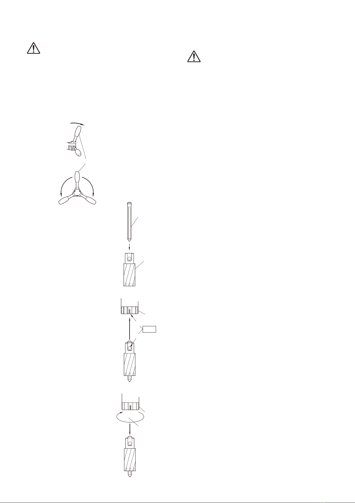
(1) Bring the Drill Motor up by turning the Rod Handle
clockwise. (Fig. 10)
Fig. 10
(2) Insert a Pilot Pin,
appropriate for the cutter
size, into the cutter.
(Fig.11)
(3) Align the depression in
the cutter with the white
line on the Sleeve, and
then insert the cutter.
When you insert the
cutte r f a r enough
the Sleeve will turn
clockwise and lock with
a clicking sound..
* W h e n you f ind i t
hard t o insert t h e
cutter, turn the Sleeve
counterclockwise and do
over. (Fig.12)
(4) To remove the cutter,
turn t h e S leeve
counterclockwise.
The cutter will come off.
(Fig.13)
5-5. Preparation of Cutting Oil
Cutting Oil Safety Precautions
WARNING
(1) Use
●Use Cutting Oil for cutting purpose only. Do not use
it for household purposes
(2) Handling Precautions
●The Cutting Oil contains amine. Do not mix it up
with rust inhibitor, etc. containing nitrite.
●Wear safety glasses for eye protection when
handling Cutting Oil: eye injury may results if it gets
into your eyes.
●Wear protective gloves for hand protection when
handling Cutting Oil: skin injury may result if it
comes into contact with your skin.
●Wear respirator when exposure to respiratory
hazards with oil mist or vapor is anticipated.
Inhalation of oil mist or vapor may make you feel
sick.
●When diluting Cutting Oil, follow the instructions per
the Operation Manual.
●Keep Cutting Oil out of reach of children.
●Do not drink Cutting Oil.
(3) First Aid
●If Cutting Oil gets into your eyes, immediately open
your eyelids with your fingers and wash your eyes
with plenty of water for at least 15 minutes. If your
eyes feel irritated, consult with a medical doctor and
follow his/her instructions.
●If Cutting Oil comes into contact with your skin,
immediately wash it away with plenty of water and
soap. Take off contaminated clothes. Clean the
clothes if you need to wear it again. If your skin
feels irritated, consult with a medical doctor for
medical instructions.
●If someone inhales oil mist or vapor, immediately
take him/her to an area where fresh air is abundant
and wrap up his/her body with a blanket, etc. to
keep body temperature. Have him/her take a
rest and consult with a medical doctor for medical
instructions.
●If someone drinks Cutting Oil, immediately make
him/her drink plenty of water and vomit it. Consult
with a medical doctor for medical instructions. When
unconscious, do not pour water into his/her mouth
nor induce him/her to vomit.
(4) Instructions in Case of Fire
●If fire breaks out in the vicinity, wear PPE (personal
protective equipment) and use foam, powder or
CO2fire extinguisher to put the fire out from the
windward.
Rod Handle
Downward Upward
Pull down out of the body
Fig. 11
Fig. 12
Fig. 13
Pilot pin
Cutter
Spindle Arbor
Turn the Sleeve
to the left
Spindle Arbor
Pull out
Sleeve
White line
Depression
Align
Sleeve

11
(5) Storage
●When storing Cutting Oil after use, put it into a
container and put a lid on for tight sealing so
that dust or moisture, which is a catalyst for
contamination, may not get in.
●Avoid direct sunlight, rainwater or the like and store
Cutting Oil in a dim cool area.
(6) Disposal
●For disposal of concentrate solution and used fluid,
request a waste-disposal company to dispose them
as industrial waste in accordance with the local laws
and regulations.
●Treat flushing water through pH adjustment,
condensation/sedimentation, activated sludge
process, activated carbon adsorption, etc., and
discharge it in accordance with the regulations of
your local municipal bylaw.
●Residual dross will remain in an emptied container:
be careful when handling an empty container.
(7) Others
●When Cutting Oil is poured into another container
for use, post chemical and label information at the
site where it is kept. At the same time, keep the
Operation Manual handy so that it can be referred to
whenever necessary.
●For further details, contact us for product safety data
sheet.
●All the information and descriptions that have been
provided are based on the currently available
documents and information, which may be revised
upon our new recognition and/or discovery.
●The precautions provided apply to regular handling.
If special handling method is used, take safety
measures that are suitable for your applications and
usage.
●The information contained herein is for your
reference purpose only, to which we make no
warranty of any kind and for which we shall not be
held responsible.
Preparation of Cutting Oil
(1-1)
Use our genuine-product Cutting Oil (blue).
If other Cutting Oil is used, the cutting
performance and service life of cutter would be
decreased.
(1-2)
Use tap water to dilute Cutting Oil by 8- to
10-fold. Do not use well water.
(1-3)
The oil tank is of the stationary type.
Remove the rubber cap and pour Cutting Oil
from the Oil Tank inlet. Do not spill Cutting Oil
on the machine.
5-6. Connecting the Power Supply Plug to Power
Source
●Before connecting the power supply plug to power
source, turn off the switch.
Always use the correct voltage for power source.
6. MACHINE OPERATION
WARNING
●Always Wear Safety Glasses.
●Always Wear Hearing Protection.
●Wear respiratory protective equipment.
●Never touch the mounted cutter and the rotating
parts of the machine such as the Spindle Arbor
after the power cable is connected to power
source.
CAUTION
●Do not use hard material such as a screwdriver,
to operate the Motor Switch. This may damage
the panel and switch, which would lead to
machine failure.
6-1 Start and Stop
(1) Magnet On
Set the Magnet Switch to On the Magnet will
activate.
(Fig. 14)
MAGNET
push
Fig. 14
(2) Drill Motor On
Set the Motor Switch to On . The Drill Motor will
start.(Fig. 15)
MOTOR
push
Fig. 15
(3) All Stop
When the Motor Switch is set to off, the Motor
will stop. When the Magnet Switch is set to the
Off position, the magnet will be deactivated and all
functions will stop.

12
6-2. Drilling Procedure
(1) Punch Marking
Put a rather large punch mark in the workpiece by
driving a punch down with a hammer. The punch
mark will be used as a guide for drilling operation
that follows, so it must be made in accurate position.
(Fig.16)
Punch Mark
Fig. 16
(2) Keep the Magnet and Workpiece Contacting
Surfaces Clean.
WARNING
●Always keep surfaces clean.
Always keep the Magnet surface clean. Always keep
the work piece surface clean. If there are any foreign
objects between the Magnet and the work piece
surfaces, this will reduce magnetic power. This could
cause the machine to move during operation. This
can result in an accident. Keep all surfaces clean of
rust, chips or other foreign material.
(3) Aligning with Punch Mark.
Turn the Rod Handle counterclockwise to slightly
lower the cutter and align the tip of Pilot Pin to the
punch mark. (Fig.17)
Fig. 17
(4) Magnet ON
CAUTION
Make sure the magnetis clinging to the workpiece.
Set the Magnet Switch to On and the magnet will be
activated. (Fig. 18)
push
MAGNET
(Fig. 18)
WARNING
●Check to see that Magnetic power is at work.
Turn on the Magnet Switch. The switch lamp will
glow and magnetic power will come on.
(5) Controlling Cutting Oil Flow.
Open the P-Valve and turn the Rod Handle. The
Pilot Pin will move up allowing Cutting Oil to flow.
(6) Mounting the Guard
Mounting the Guard as shown. (Fig.19)
Guard
Fig. 19
(7) Drill Motor ON
CAUTION
Do not touch the rotating parts.
Set the Motor Switch to On . The Drill Motor will
start. (Fig. 20)
(Fig. 20)
WARNING
●Do not touch revolving parts.
Press the Drill Motor ON Switch to start the Drill
Motor
(8) Drilling
Automatic Feed
CAUTION
●Once drilling feed has started, do not touch the
Rod Handle until drilling cycle is complete.
To start automatic feed, push the Rod Handle toward
the machine. As the cutter will be fed at low speed
at the start you do not have to use manual feed.
(Fig.21)
Automatic feed
Fig. 21
Punch Mark
ON OFF
Rod Handle
MOTOR
push

13
CAUTION
●Do not use automatic feed when the workpiece
has a tapered bottom surface through which a
hole is to be drilled.
When putting a hole through workpiece with a
tapered bottom surface or bottom surface with a
radius, such as angle, channel, H-section steel,
etc., use low feed rate at the start as well as toward
the end of drilling operation where the likelihood of
tool chipping is high. (Fig.22)
R
Fig. 22
(9) Finishing Drilling Operation
WARNING
●
When drilling cycle is complete, the Drill Motor
will stop automatically. If it does not, it is a
machine failure. Turn off the Motor Switch and
contact sales agent through which you have
purchase your machine or an authorized dealer
near you for repair.
●
Be alert at the end of drilling operation when
slug will automatically pop out. Do not touch
slug: it is very hot and has sharp edges.
When drilling cycle is complete, the Drill Motor will
come to a complete stop automatically. Once it
has come to a stop, pull the Rod Handle outward
away from the machine and turn off the automatic
feed switch. Turn the Rod Handle clockwise to raise
the Drill Motor. Then promptly turn off the Magnet
Switch. If a Magnet is left alone with its switch
turned on for many hours, electric current will keep
flowing through the Magnet at the cost of shortened
service life.
(10) Removing Slug
Do not proceed to the next operation without
removing the slug from the operation just finished.
At the end of drilling operation slug will pop out
automatically ejected by the spring-operated Pilot
Pin. Should a slug left in the hold sticking, remove it
from the hole by tapping the collar of the slug with a
needle stick or something. (Fig.23)
Fig. 23
6-3. Drilling Oblong Hole
CAUTION
●
Always drill oblong hole manually and slowly.
Drill oblong hole in the order of ①,②,③. For the
steps ②and ③, use manual feed and take care so
that the cutter may not be fed into the workpiece with
too much force. If automatic feed is used, damage to
the cutter or unexpected accident may result. Use a
file to take off any sock that is left unmachined.
Spacing between each step of drilling operations
should be so arranged that the Pilot Pin will always hit
the sold material yet to be machined. (Fig.24)
Fig. 24
6-4. Drilling Stacked Plates
CAUTION
●
Remove slug as each plated is finished:
otherwise, being blocked by the slug left
unremoved, the cutter cannot cut into the next
layer of plate, which results in the Magnet base
being pushed up possibly causing accident.
●
For stacked plates drilling, always use manual
feed and drill slowly and carefully.
●
Before drilling stacked plates, securely clamp
the plates together in place.
●
When drilling stacked plates, retract the cutter as
each layer of plate is finished in order to remove
slug from the drilling area, then put another hole
in the next layer of plate.
File away any excesses

14
7. TROUBLESHOOTING
WARNING
●
Never attempt to repair machine yourself: injury or damage to equipment may result.
●
Please feel free to consult the sales agent through which you have purchase your machine or an
authorized dealer, when the following symptoms appear or when you have any questions about our
products.
This machine is electronically controlled. It will stop when it picks up noise from power source or when malfunction
occurs to the electronic control. When you notice the following symptoms, pull the Rod Handle outward away
from the machine to turn OFF automatic feed and raise the Drill Motor to ensure safety and conduct inspection.
Problem Causes Solutions
Switch lamp does not come
on when Magnet Switch is
turned on.
Power supply plug is not connected to
socket.
Connect power supply plug to socket.
Drill Motor does not start
when Motor Switch is turned
on.
Magnet is disconnected. Request for repair.
Limit switch is activated near the lower
limit of drill stroke.
Slightly raise Drill Motor and release
limit switch.
Drill Motor stops during
drilling. (Magnet is not
working with Magnet lamp not
illuminating.)
Power failure has occurred or power
supply plug is disconnected.
After power failure is restored or power
supply plug is re-connected, turn on
Motor Switch again.
Drill Motor stops completely
in th e middle o f drilling
operation.
No Cutting Oil or insufficient Cutting Oil Increase flow rate of Cutting Oil.
Cutting edges jammed and stuck with
cutting chips.
Remove.
Worn cutting edge. Regrind or replace with new one.
Using cutter of other make Use Nitto brand cutter.
Using Cutting Oil of other made. Use Nitto brand Cutting Oil.
Switching over to auto feed in the
middle of operation that started with
manual feed.
Use the automatic feed from the
beginning.
Temporal glitch with electronic control. Restart .
Overload protection triggered Restart .
Lateral shifting of Magnet is
detected by lateral position
sensor, bringing machine to a
compete stop.
Workpiece too thin. Use back-up plate: thickness 13/32” (10
mm) or more.
Chips under Magnet base. Clean it up.
Worn cutting edge. Regrind or replace with new one.
Effective Magnetic force too weak. Ask for repair.
Drill Motor doesnot come to a
stop when drilling operation is
complete.
Near-exit restarting Normal.
Motor Switch OFF
Almost no cutting pressure throughout
drilling operation
(workpiece too thin.)
Normal.
Motor Switch OFF
No lubrication to Arbor Body or needle
bearing.
Lubricate.
Drill Motor stops within
several seconds after Motor
Switch is turned on.
Frozen machine Turn on and off the switch several times
to warm up machine.

15
8. MAINTENANCE/SERVICE
WARNING
●
Always disconnect the power and turn off the
switch before attempting any maintenance.
Failure to disconnect the power and turn off the
switch during set up, inspection or maintenance
can cause accidents and severe injuries.
●
Check to see periodically that mounting screws
are tight. If you find them loose, retighten.
8-1. Tighten Set Screw When Machine is Not Used
For the purpose of safety, when you do not use
the machine temporally or on a long-term basis,
raise the Drill Motor and set it in position with the
Set Screw so that it will not come down on its own
weight. If you leave the machine alone with the
Drill Motor in a lowered position, the Pilot Pin and/
or cutter may be damaged when the machine is
relocated. (Fig.25)
8-2. Grease the Sliding Surfaces from Time to Time
Grease the machine body and Slide Board from time
to time. (Fig.25)
8-3. Slide Board Clearance Adjustment
Excessive clearance between the machine body
and Slide Board would deteriorate not only drilling
performance but also cutting tool life to a substantial
degree. If you find excessive clearance, make
adjustment by tightening 5 slide board adjusting
screws on the side of the machine using the same
torque all round so that the Drill Motor will not come
down on its own weight. (Fig.25)
8-4. Bracket Inspection and Oiling
Among other things, drilling accuracy hinges on the
Bracket that supports the Arbor Body. See that the
(three Hexagon Socket) Bracket mounting bolts are
tight, from time to time. (Fig.25)
Fig. 25
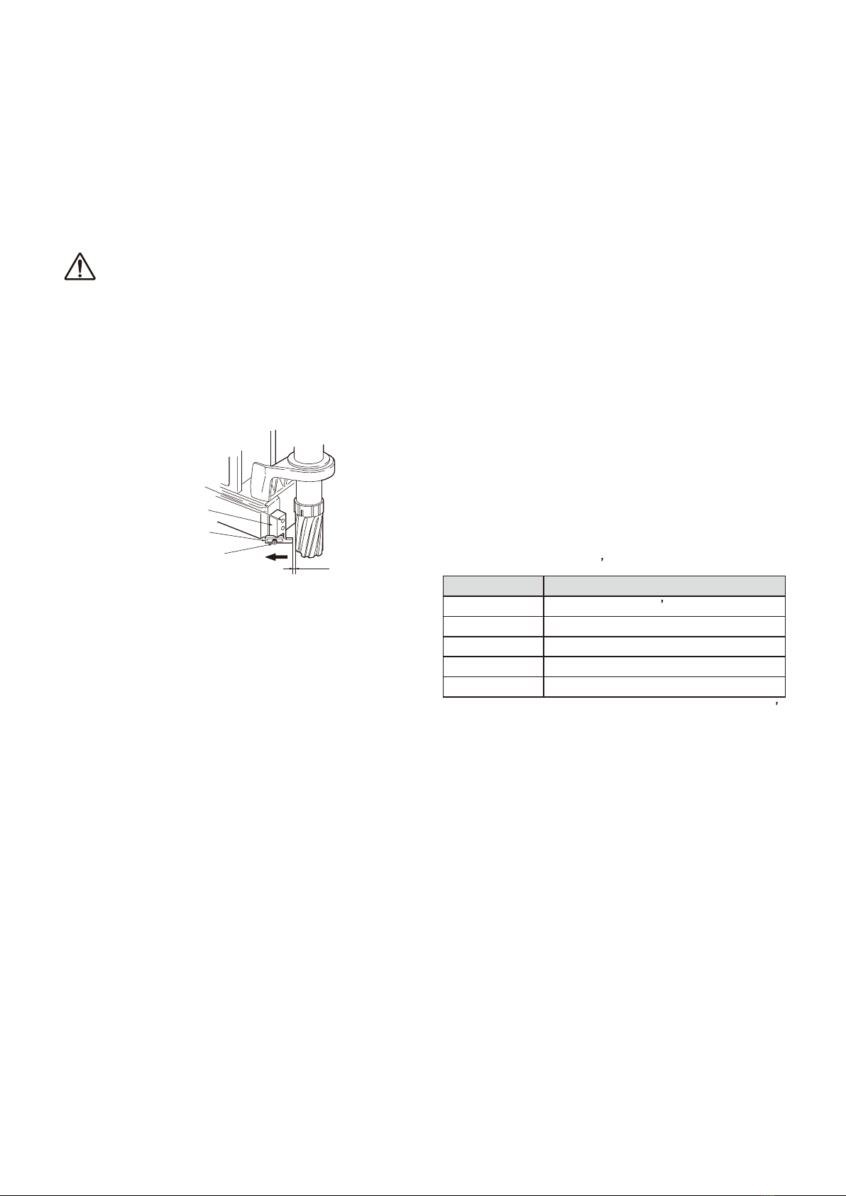
8-5. Keep the Tip of Pilot Pin Sharp
When the tip of Pilot Pin gets dull, it sometimes fails
to seat into punched hole, causing drilling accuracy
to deteriorate. See that the tip is sharp from time to
time.
If you find it too dull, regrind or replace as required.
When regrinding do so carefully, for grinding with too
much force may cause the tip to get dull or soften
the material to such a degree that it is no longer
usable. (Fig.26)
Fig. 26
8-6. Recovery Measures When Pilot Pin Gets
Jammed
When you change cutting tool you also change
Pilot Pin, which acts as a guide for the cutting tool.
However there are times when the pin does not
come off easy with cutting chips in the clearance
between the cutting tool and pin, causing jamming.
In such case, tap the tip of Pilot Pin with a wooden
hammer, etc., and pull it off. (Fig.27)
Sharpen
the tip
Optimal angle 70°
Pilot Pin
16
Fig. 27
8-7. Cutter Regrinding
When you need to regrind cutter, please contact
sales agent through which you have purchased your
machine or an authorized dealer near you.
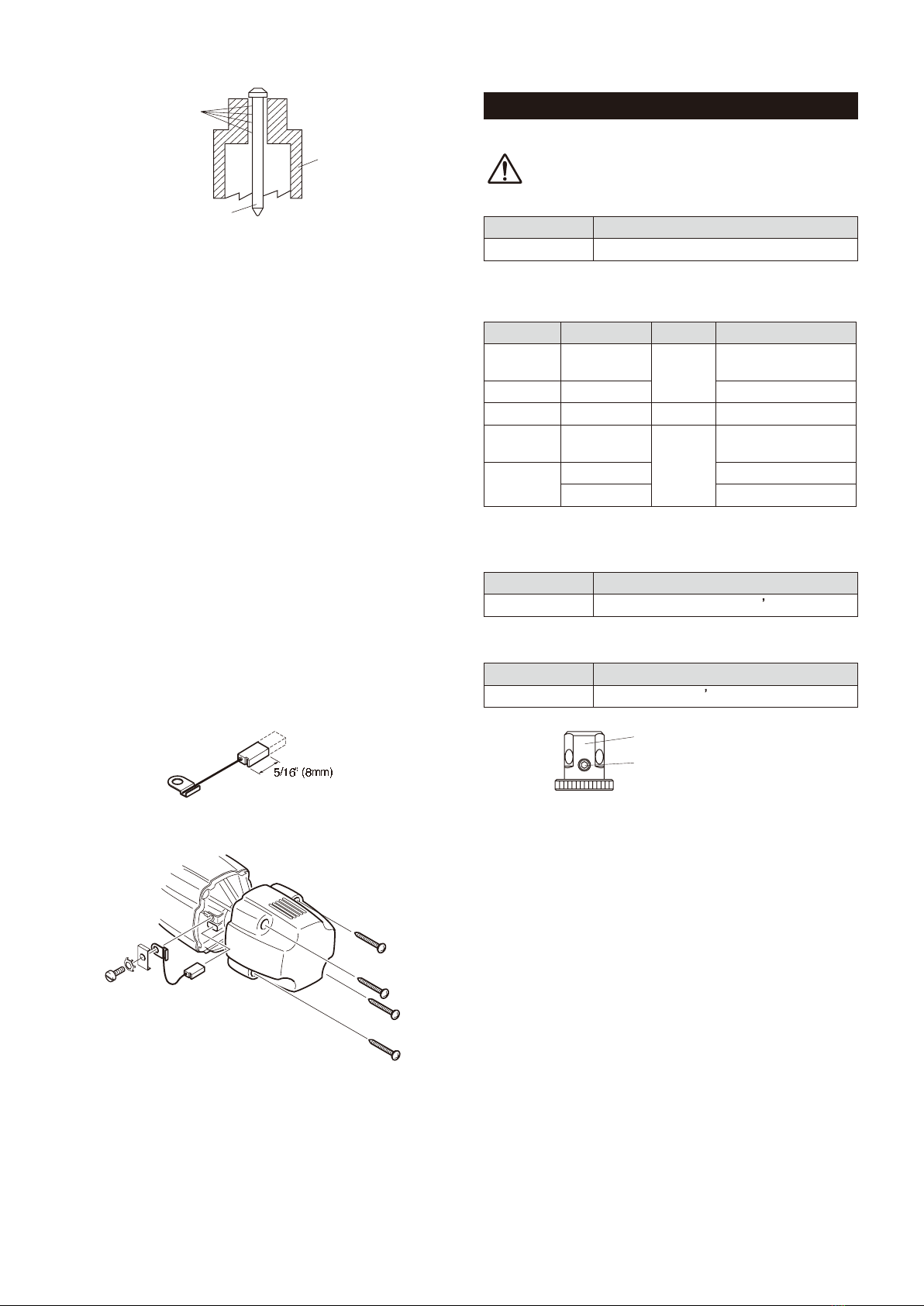
8-8. Carbon Brushes Inspection and Replacement
Check Carbon Brushes for wear periodically.
When the length of Carbon Brushes gets as short
as 5/16” (8 mm), replace it with a new one, for, if you
do not, chances are that you will have a rectification
problem which may cause machine failure. (Fig.28)
(1) Loosen the tap screws to remove the cap.
(2)
Take out the Carbon Brush and replace it with a
new one.
(3)
Put the cover on and securely tighten the tap
screws. When tightening the tap screws, see
that the tap screws are screwed in along the
existing screw threads – without cutting new
threads.
(4)
After replacement, run the machine with no load
for approx. 10 minutes.
Fig. 28
Fig. 29
9. OPTIONAL PARTS
9-1. Nitto-Brand Cutting Oil
CAUTION
Use Nitto-brand Cutting Oil for Atra Ace.
Part No. Part Name
TB01507 Cutting Oil 2ℓ(Light Blue)
9-2. Pilot Pin
(metric sizes)
Part No. Part Name
Depth(mm)
Applicable cutter (mm)
TK01167
Pilot Pin 06025
25
Hi-broach 14 - 17 dia.
TJ12696
Pilot Pin 08025
Hi-broach 17.5 - 35 dia.
TJ15859
Pilot Pin 08035
35
Jetbroach 17.5 - 35 dia.
TK01166
Pilot Pin 06050
50
Hi-broach 14 - 18 dia.
TJ16019
Pilot Pin 08050
Hi-broach 19 - 35 dia.
(TK00802)
Pilot Pin 0850
Jetbroach 17.5 - 35 dia.
※( ):Special Order
9-3. Supporting Magnet Assʼy
Part No. Part Name
TB04374 Supporting Magnet Assy
9-4. Sleeve 6.5 Assʼy for Twist Drills (Fig.30)
Part No. Part Name
TB02536 Sleeve 6.5 Assy
Sleeve 6.5
Hex. Socket Set Screw
with Cup Point 6X5
Fig. 30
Cutting Chips
Pilot Pin
Cutter
17
9-5. Chip Breaker
When chips are not smoothly discharged during
drilling, the overload detection will be frequently
triggered to stop the Drill Motor, particularly when
plate thickness is 1-3/8” (25 mm) or thicker. In such
case, an optional Chip Breaker may be used to ease
chip congestion.
9-5-1. Mounting Chip Breaker
CAUTION
●
When setting Chip Breaker, see that the tip of
blade may not come into contact with cutting
tool.
Chip Breaker breaks cutting chips formed in drilling
into small pieces and facilitates chip discharging.
Hex. Socket Head
Cap Screw 5X12
Hex. Socket Head
Cap Screw 6X10
Blade Base
Blade
0.5-0.8mm
Fig. 31
(1)
Mount Blade Base. (Fig.31)
●Use two Hex. Socket head Cap Screws 6 X 10
to mount the Blade Base on the front face of
Magnet.
Here, see that the bottom face of the Blade
Base is flush with the bottom face of Magnet.
When the bottom face of the Blade Base sticks
out from the bottom face of the Magnet, the
magnetic force it sends out can not be made
fully use of for secure fastening.
●Use the Hex. Socket head Cap Screws 5 ×
12 to mount a blade to the Blade Base in the
direction as shown in the figure.
(2)
Mount cutter.
Loosen the Hex. Socket head Cap Screws 5 ×12
and pull the Blade in the direction as shown by the
arrow until it no longer moves. And then, mount a
cutter.
(3)
Set the blade.
Set the Blade in the way that the cutter and the
blade will have a clearance of 0.5 mm - 0.8mm
and fasten it securely to the Blade Base with Hex.
Socket head Cap Screws 5 ×12.
9-5-2. Chip Breaker Assy
Part No. Part Name
TB05186 Chip Breaker Assy
(TQ04949) Blade
(TQ04950) Blade Base
(TP14178)
Hex. Socket Head Cap Screw 6
×
10
(TP01945) Hex. Socket Head Cap Screw 5×12
The part number with ( )are include in the Ass y
parts written above them.

18
TK00355 31 ×25
TK00356 32 ×25
TK00357 33 ×25
TK00358 33.5 ×25
TK00359 34 ×25
TK00360 34.5 ×25
TK00361 35 ×25
TK00347 24.5 ×25
TK00348 25 ×25
TK00349 26 ×25
TK00350 26.5 ×25
TK00351 27 ×25
TK00352 28 ×25
TK00353 29 ×25
TK00354 30 ×25
TK00339 20 ×25
TK00340 21 ×25
TK00341 21.5 ×25
TK00342 22 ×25
TK00343 22.5 ×25
TK00344 23 ×25
TK00345 23.5 ×25
TK00346 24 ×25
Part No.
Diameter×Depth
Part No.
Diameter ×Depth
Part No.
Diameter ×Depth
Part No.
Diameter ×Depth
TK00700 14 ×25
TK00701 15 ×25
TK00702 16 ×25
TK00703 17 ×25
TK00335 17.5 ×25
TK00336 18 ×25
TK00337 19 ×25
TK00338 19.5 ×25
9-6 Ordering parts
Hi-Broach One-touch Type (metric sizes)
Jetbroach One-touch Type (metric sizes)
Jetbroach One-touch Type (metric sizes)
TK00325 33 ×35
TK00326 34 ×35
TK00327 34.5 ×35
TK00328 35 ×35
Part No.
Diameter×Depth
Part No.
Diameter ×Depth
Part No.
Diameter ×Depth
Part No.
Diameter ×Depth
TK00317 26 ×35
TK00318 26.5 ×35
TK00319 27 ×35
TK00320 28 ×35
TK00321 29 ×35
TK00322 30 ×35
TK00323 31 ×35
TK00324 32 ×35
TK00309 21.5 ×35
TK00310 22 ×35
TK00311 22.5 ×35
TK00312 23 ×35
TK00313 23.5 ×35
TK00314 24 ×35
TK00315 24.5 ×35
TK00316 25 ×35
TK00301 17.5 ×35
TK00302 18 ×35
TK00303 18.5 ×35
TK00304 19 ×35
TK00305 19.5 ×35
TK00306 20 ×35
TK00307 20.5 ×35
TK00308 21 ×35
TK00387 21.5 ×50
TK00388 22 ×50
TK00389 22.5 ×50
TK00390 23 ×50
TK00391 23.5 ×50
TK00392 24 ×50
TK00393 24.5 ×50
TK00380 17.5 ×50
TK00381 18 ×50
TK00382 19 ×50
TK00383 19.5 ×50
TK00384 20 ×50
TK00385 20.5 ×50
TK00386 21 ×50
Part No.
Diameter×Depth
Part No.
Diameter ×Depth
Part No.
Diameter ×Depth
Part No.
Diameter ×Depth
TK00394 25 ×50
TK00395 26 ×50
TK00396 26.5 ×50
TK00397 27 ×50
TK00398 28 ×50
TK00399 29 ×50
TK00400 30 ×50
TK00401 31 ×50
TK00402 32 ×50
TK00403 33 ×50
TK00404 34 ×50
TK00405 35 ×50

OverseasAffiliates/Offices
NIT
TOKOHKIU.S.A.,Inc.
4525
TurnberryDrive,HanoverPark,IL60133,U.S.A
T
el:(1)-630-924-9323 Fax:( 1)-630-924-0303
http
://www.nittokohki.com/index.html
NIT
TOKOHKIEUROPECo.,Ltd.
Unit21
,EmpireCentre,ImperialWay,
W
atfordHertfordshire,WD244TS,UnitedKingdom
T
el:( 44)-01923-239668 Fax:( 44)-01923-248815
http
://www.nitto.co.uk/
NIT
TOKOHKIDEUTSCHLANDGmbH
Lerchenst
r.47,D-71144Steinenbronn,Germany
T
el:( 49)-7157-22436 Fax:(49)-7157-22437
http
://www.nitto-kohki.de/
NIT
TOKOHKIAUSTRALIAPty.Ltd.
77Brandl
Street,EightMilePlainsQLD4113,
Au
stralia
T
el:( 61)-7-3340-4600 Fax:( 61)-7-3340-4640
http
://www.nitto-australia.com.au/
NITTOKOHKICo.,Ltd. SingaporeBranch
10UbiCrescent#01-62,UbiTechparkLobbyD,
Singapore408564
Tel: (65)-6227-5360 Fax:(65)-6227-0192
http://www.nitto-kohki.co.jp/e/nksb/
NITTOKOHKICo.,Ltd. ShanghaiRepresentativeOffice
#1117RuijingBuilding,MaomingSouthRoad,
Shanghai200020China
Tel: (86)-21-6415-3935 Fax:(86)-21-6472-6957
http://www.nitto-kohki.cn/
NITTOKOHKICo.,Ltd. ShenzhenRepresentativeOffice
#0726InternationalCultureBuilding,3039,Shennan
ZhongRd.,FutianDistrict,Shenzhen,518003China
Tel:(86)-755-8375-2185Fax:(86)-755-8375-2187
http://www.nitto-kohki.cn/
NITTOKOHKICo.,Ltd. BangkokRepresentativeOffice
38Q,HouseConventBldg,7thFloor,Unit7A,
ConventRd,Silom,Bangkok,10500Thailand
Tel: (66)-2-632-0307 Fax:(66)-2-632-0308
http://www.nittobkk.com/engindex.htm
ECDECLARATION OF CONFORMITY
Weherebydeclarethatthefollowingourproductconformswiththeessential healthandsafetyrequirementsofECDirectives.
Product PORTABLEMAGNETICDRILLINGMACHINE
Model ATRAACE WA-3500
SerialNo XXXXXX XXXX Christianera
Consecutivenumbers(00001 99999)
Christianeraʼslastdigit(0 9)
Manufacturer NITTOKOHKICo.,Ltd.
2-9-4, Nakaikegami, Ohta-ku,Tokyo,146-8555,Japan
AuthorisedCompilerintheCommunity
MasatoshiOgue
President
NITTOKOHKIEUROPECo.,Ltd.
Unit21,Empire Centre,ImperialWay,WatfordHertfordshire,WD24 4TS,UK
Tel:(44)-01923-239668 Fax:(44)-01923-248815
Directive 98/37/ECand2006/42/ECMachineryDirective
2006/95/ECLowVoltageDirective
2004/108/ECEMCDirective
Theaboveproducthasbeenevaluatedforconformitywithabove directivesusingthefollowingEuropeanstandards.
Thetechnicalconstructionfile(TCF)forthisproductisretainedandcompliedattheabovemanufacturerʼslocation.
MachineryDirective/LowVoltageDirective
ENISO12100-1:2003,ENISO12100-2:2003,ENISO14121-1:2007,EN60204-1:2006,others
EMCDirective EMI EMS
EN55014-1:2006 EN55014-2:1997+A1:2001:Category
EN61000-3-2:2006 EN61000-4-2:1995+A1:1998+A2:2001
EN61000-3-3:1995/A1:2001+A2:2005 EN61000-4-4:2004
EN61000-4-5:1995+A1:2001
EN61000-4-6:1996+A1:2001
EN61000-4-11:2004
Name K.Kishi
Title: GENERALMANAGERMACHINETOOLS DIV.
Beingtheresponsiblepersonappointedandemployedthemanufacturer.
PrintedinJAPAN TQ12846-0
Printed in JAPAN TQ12846-6
Table of contents
Other Nitto Drill manuals


Popular Drill manuals by other brands


Bosch
Bosch 38636-01 - 36V Cordless Litheon Brute Tough... Operating/safety instructions

Bosch
Bosch GBM 10 operating instructions

Panasonic
Panasonic EY6803 - HAMMER DRILL DRIVER 12V operating instructions

Kernlochbohrer
Kernlochbohrer DKB Series operating instructions

Skil
Skil 6271 Original instructions

Craftsman
Craftsman 315.101532 Operator's manual