JEI AIRBEAST 35 ATEX User manual


AIRBEAST 35 ATEX
AIRBEAST 35 ATEX Operator’s Manual
2
Contents
1. GENERAL INFORMATION............................................................................................... 3
1.1. Application................................................................................................................. 3
1.2. Technical data............................................................................................................ 3
1.3. Design ....................................................................................................................... 4
1.4. Equipment included ................................................................................................... 4
1.5. Air preparation unit (optional)..................................................................................... 5
2. SAFETY PRECAUTIONS.................................................................................................. 5
3. STARTUP AND OPERATION........................................................................................... 7
3.1. Mounting and operation of annular cutter................................................................... 7
3.2. Preparation................................................................................................................ 9
3.3. Drilling.......................................................................................................................12
3.4. Maintenance of air preparation unit...........................................................................13
4. DECLARATION OF CONFORMITY.................................................................................14
5. QUALITY CERTIFICATE..................................................................................................15
6. WARRANTY CARD..........................................................................................................16

JEI GroupLtd AIRBEAST 35 ATEX
AIRBEAST 35 ATEX Operator’s Manual
3
1. GENERAL INFORMATION
1.1. Application
The AIRBEAST 35 ATEX air drilling machine with magnetic base is designed to drill
holes with diameters of up to 35 mm (1.38’’) to the maximum depth of 25 mm (0.98’’)
through the use of annular cutters. The machine is ATEX II 2G/D cIIC T6/T4 certified,
which allows for working in explosive environments.
The magnetic base allows the drilling machine to be fixed to ferromagnetic surfaces
with aforce that ensures user safety and proper machine operation. A safety chain
protects the machine from dropping in case of a pressure loss.
1.2. Technical data
Pressure
6 bar
Air connection
GZ 3/8’’ BSPT
Power
800 W
Air consumption
1400 l/min (50 CFM)
Cutter holder
19 mm Weldon (0.75’’)
Maximum drilling diameter
35 mm (1.38’’)
Maximum drilling depth
25 mm (0.98’’)
Magnetic base holding force
(surface with the thickness of 22 mm and roughness Ra= 1.25)
6 500 N
Magnetic base dimensions
80 mm × 80 mm × 143 mm
3.1’’ × 3.1’’ × 5.6’’
Spindle stroke
39 mm (1.54’’)
Rotational speed under load
240 min-1
Minimum workpiece thickness
10 mm (0.39’’)
Noise level
over 70 dB
Required ambient temperature
0–40°C (32–104°F)
Weight
17 kg (37 lbs)
460 mm (18.1’’)
183 mm (7.2’’)
191 mm (7.5’’)
JEI GroupLtd AIRBEAST 35 ATEX
AIRBEAST 35 ATEX Operator’s Manual
4
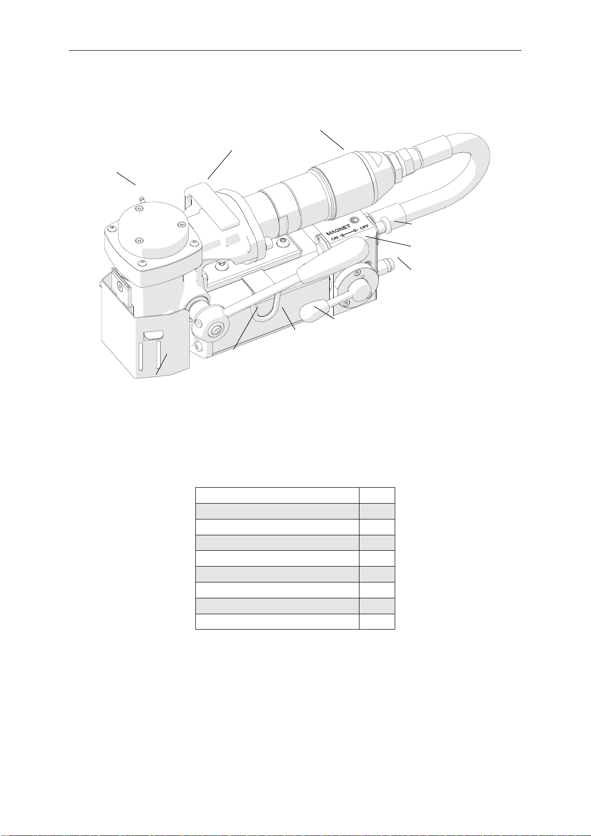
1.3. Design
Figure 1. AIRBEAST 35 ATEX design
1.4. Equipment included
The AIRBEAST 35 ATEX drilling machine is supplied in a metal box with complete
standard equipment. The included equipment consists of:
•pneumatic drilling machine
1 unit
•metal box
1 unit
•feed lever
1 unit
•cooling system bottle 0.5 l
1 unit
•pilot pin
1 unit
•safety chain
1 unit
•4 mm hex wrench
1 unit
•5 mm hex wrench
1 unit
•Operator’s Manual
1 unit
lug for safety chain
chip guard
magnetic base
ON/OFF switch
air connection
carrying handle
coupling for
cooling system bottle
magnetic base
feed lever
MOTOR lever
air motor

JEI GroupLtd AIRBEAST 35 ATEX
AIRBEAST 35 ATEX Operator’s Manual
5
1.5. Air preparation unit (optional)
2. SAFETY PRECAUTIONS
1. Before beginning, read this Operator’s Manual and complete proper occupational
safety and health training.
2. The machine must be used only in applications specified in this Operator’s Manual.
3. The machine must be complete and all parts must be genuine and fully operational.
4. Thesupplyspecificationsmustconformtothosespecifiedontheratingplate.
5. Supply the machine only with clean and lubricated air. The air installation must be
equipped with filter, regulator, and lubricator.
6. Never carry the machine by the motor hose, nor yank the supply hose to
disconnect the connector.
7. Transport and position the machine using the carrying handle, with the magnet
switch set to position OFF.
8. Untrained bystanders must not be present in the vicinity of the machine.
9. Before beginning, check the condition of the machine and air supply, including the
supply hose, connector, and cutters.
10. Keep the machine dry. Exposing it to rain, snow, or frost is prohibited.
11. Never stay below the machine placed at heights.
12. Keep the work area well lit, clean, and free of obstacles.
13. Mount the annular cutter securely using the set screws. Remove adjusting keys
and wrenches from the work area before connecting the machine to the supply.
14. Never use dull or damaged cutters.
15. Mount and dismount cutters using protective gloves and with the machine
unplugged from the supply.
16. Never use annular cutters without the pilot pin except for establishing incomplete
through holes.
Part number (filter, regulator, lubricator):
ZST-000021

JEI GroupLtd AIRBEAST 35 ATEX
AIRBEAST 35 ATEX Operator’s Manual
6
17. Mount only annular cutters with the maximum drilling diameter and drilling depth
of 35 mm (1.38’’).
18. Using the machine on surfaces that are rusty, covered with a thick paint layer,
uneven, or not stiff is prohibited.
19. Use the safety chain in all operating positions. The chain must not be loose and
must be fastened to a securely fixed element.
20. Before every use, inspect the machine to ensure it is not damaged. Check
whether any part is cracked or improperly fitted. Make sure to maintain proper
conditions that may affect the operation of the machine.
21. Always use eye and hearing protection and protective clothing during operation.
Do not wear loose clothing.
22. The whole surface of the magnetic base bottom must stick to the workpiece.
Before every positioning, wipe the workpiece with coarse-grained sandpaper.
23. Do not touch moving parts or chips formed during milling. Prevent objects from
being caught in moving parts.
24. After every use, remove metal chips and coolant remainder from the machine. Do
not remove chips with bare hands.
25. Maintain the machine and tools with care. Cover steel parts with a thin grease
layer to protect them against rust when not in use for a longer period.
26. Perform maintenance only with the machine unplugged from the supply.
27. Perform repairs only in a service center appointed by the seller.
28. If the machine falls on a hard surface, from height, is wet, or has any other
damage that could affect the technical state of the machine, stop the operation
and immediately send the machine to the service center for inspection and repair.
29. Never leave the machine unattended during operation.
30. Remove from the worksite and store in an isolated and dry location when not in
use, previously removing the cutter from the arbor.

JEI GroupLtd AIRBEAST 35 ATEX
AIRBEAST 35 ATEX Operator’s Manual
7
3. STARTUP AND OPERATION
3.1. Mounting and operation of annular cutter
With the machine unplugged from the supply, proceed as follows. Maximally raise the
chip guard (1, Figure 2) and rotate the feed lever counterclockwise (2) to access the
set screws 3.Then, insert the proper pilot pin into the annular cutter (4), after which
wear protective gloves and place the cutter into the arbor (5)in such away to align the
flats 6with the set screws 3.Finally, tighten both set screws with 4 mm hex wrench. To
dismount the cutter, proceed in reverse order.
All safety precautions must be closely observed.

JEI GroupLtd AIRBEAST 35 ATEX
AIRBEAST 35 ATEX Operator’s Manual
8
Figure 2. Method of mounting the annular cutter
Figure 3 shows how annular cutters operate. As the cutter penetrates the workpiece,
the pilot pin recesses into the arbor and tightens the spring. As a result, after the cutter
goes through the entire thickness, the slug core is expelled from the cutter.
4
5
3
6
1
2

JEI GroupLtd AIRBEAST 35 ATEX
AIRBEAST 35 ATEX Operator’s Manual
9
Figure 3. Annular cutters operation
Annular cutters are designed to establish only through holes shown in Figure 4.
Establishing incomplete through holes requires not using the pilot pin.
Figure 4. Types of holes to establish with annular cutters
3.2. Preparation
Before beginning, clean steel parts, especially the Weldon shank, from grease used
to preserve the machine for storage and transport.
complete through holes
incomplete through holes
slug core
spring
pilot pin
annular cutter
arbor
JEI GroupLtd AIRBEAST 35 ATEX
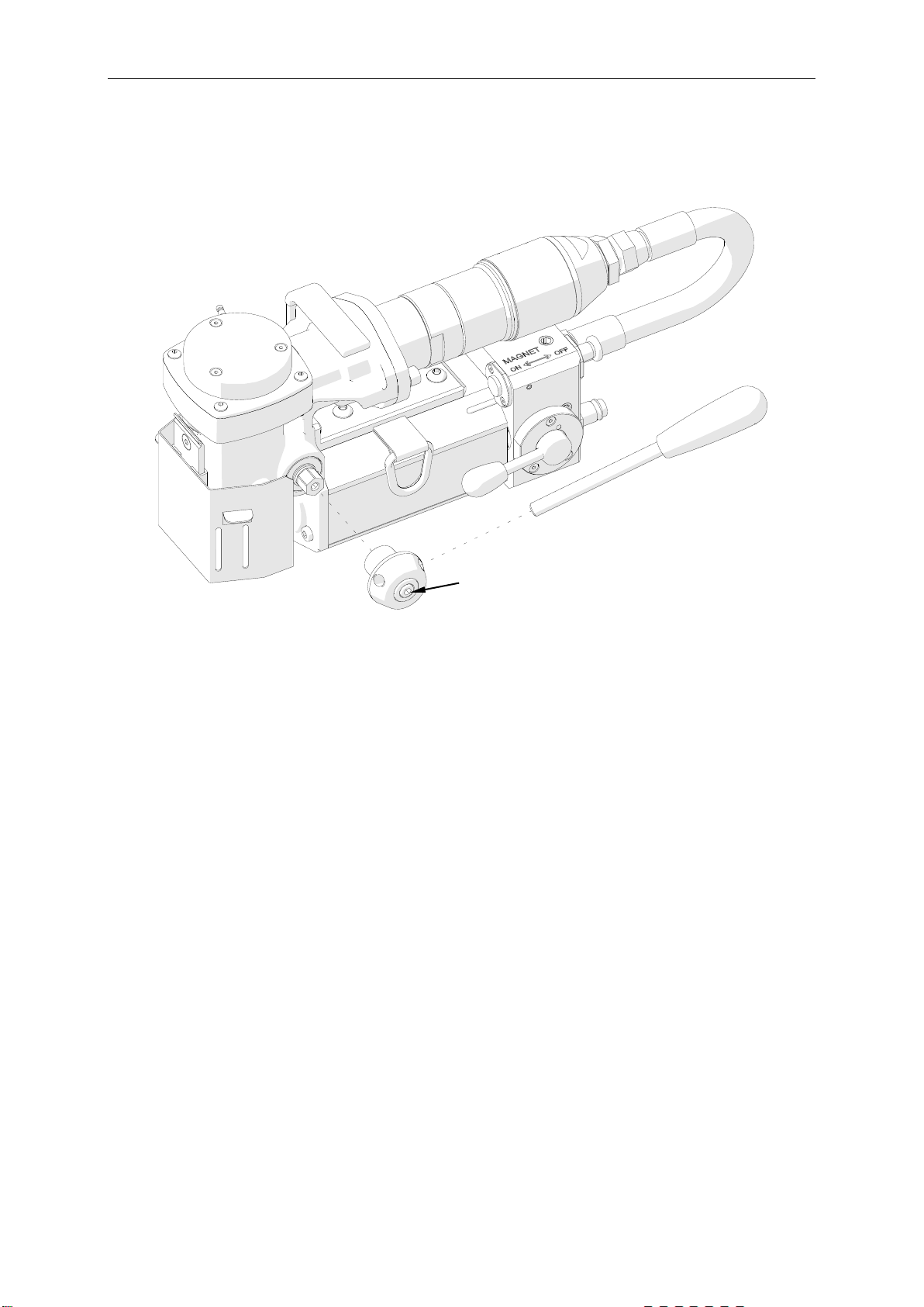
AIRBEAST 35 ATEX Operator’s Manual
10
Then, screw in the feed lever (1,Figure 5).To mount the lever at the opposite side of
the machine, use 5 mm hex wrench to loosen the screw 2mounting the head and
reposition the head to the other side, and tighten the screw.
Figure 5. Method of mounting the feed lever
Mount the annular cutter into the arbor in the manner described before.
Connect the machine to a correctly prepared air supply of sufficient purity using
a hose with the internal diameter of at least 10 mm (0.4’’). The air installation must be
equipped with an air preparation unit: filter, regulator, and lubricator.
Position the machine on a flat ferromagnetic surface (some types of stainless and
acid-proof steel do not conduct magnetic flux) with thickness of at least 10 mm (0.4’’).
The workpiece must be clean, without rust or paint that decrease the holding force of
the magnetic base.
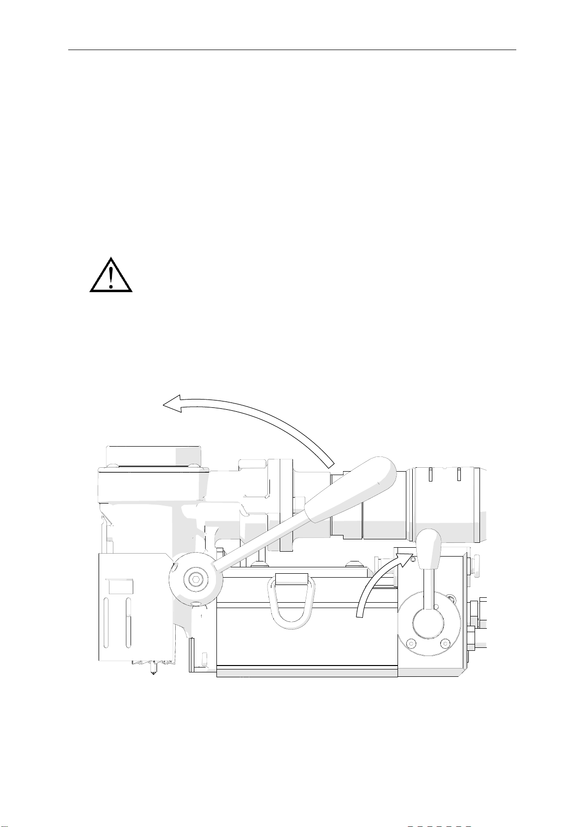
With the MOTOR lever set in the position from Figure 6, enable the magnetic base by
toggling the MAGNET switch to position ON.
2
1

JEI GroupLtd AIRBEAST 35 ATEX
AIRBEAST 35 ATEX Operator’s Manual
11
Figure 6. Method of enabling the magnetic base
Protect the machine using the safety chain to prevent possible injury if the machine
loses magnetic adhesion in case of a pressure loss.
Figure 7. Method of protecting the machine using the safety chain
a)
b)
c)
JEI GroupLtd AIRBEAST 35 ATEX
AIRBEAST 35 ATEX Operator’s Manual
12
To do this, attach the end links of the chain to the snap hooks and grasp the hooks to
the lugs located on both sides of the machine (Figure 7). The chain must not be
loose. Wrap the chain around the workpiece if possible.
When working in the position from Figure 7a and 7c, fill the cooling system bottle with
acutting fluid and attach the bottle hose to the coupling (Figure 1). Do not use pure
water as the cutting fluid, however, using emulsions formed from mixing water and
drilling oil is also satisfactory. Then, press the lever of the bottle several times, after
which rotate the feed lever to initially apply pressure on the pilot pin. The fluid will fill
the system and will begin flowing from the inside of the cutter.
3.3. Drilling
Start the motor by positioning the MOTOR lever vertically (1, Figure 8). Rotate the
feed lever counterclockwise (2) to bring the cutter close to the workpiece and gently
begin drilling. Maintain constant pressure on the lever. Accomplish the hole in one pass.
Figure 8. Method of starting the motor
Use a cooling paste when working in inverted positions
(Figure 7b).
1
2

JEI GroupLtd AIRBEAST 35 ATEX
AIRBEAST 35 ATEX Operator’s Manual
13
Once the hole is accomplished, retract the cutter from the workpiece and stop the
motor by rotating the MOTOR lever counterclockwise to the horizontal position. To
move the machine to another drilling spot, first disable the magnetic base by positioning
the MAGNET switch in position OFF.
Once the work is finished, unplug the machine from the supply, clean chips and
coolant remainder from the machine and cutter, after which remove the machine from
the worksite.
Press the pilot to expel the coolant remaining within the system. Before inserting the
drilling machine into the toolbox, disassemble the cooling system bottle and remove
the cutter from the arbor using protective gloves.
3.4. Maintenance of air preparation unit
Maintain the air preparation unit as required to keep the water trap drained, filter
cleaned, and the lubricator oil reservoir filled so that there is a drop of oil every 2–5
seconds. Use only oil which ignition temperature exceeds 260°C (500°F). If the
machine is to be left idle for at least 24 hours, increase the delivery of oil and run the
motor for 2–3 seconds, which will prevent rusting and degrading of the rotor vanes.
When the cutter goes through the material, the slug core
is expelled from the tool with a significant force.

JEI GroupLtd AIRBEAST 35 ATEX
AIRBEAST 35 ATEX Operator’s Manual
14
4. DECLARATION OF CONFORMITY
EC Declaration of Conformity
We
JEI GROUP LTD
Unit 21 Empire Business Park
Enterprise Way, Burnley
Lancashire BB12 6LT
Declare with full responsibility that product:
AIRBEAST 35 ATEX AIR DRILLING MACHINE
WITH MAGNETIC BASE
ATEX group II category 2 G/D
Which the declaration applies to is in accordance with the following standards:
•EN ISO 12100
•EN 1127-1
•EN 1127-2+A1
•EN 13463-1
•EN 13463-5
and satisfies safety regulations of the guidelines: 2006/42/EC, 94/9/EC.
Burnley, 1ST December 2017 ___________________________
David McFadden
Managing Director

JEI GroupLtd AIRBEAST 35 ATEX
AIRBEAST 35 ATEX Operator’s Manual
15
5. QUALITY CERTIFICATE
Machine control card
AIRBEAST 35 ATEX Air Drilling Machine with Magnetic
Base
Serial number................................................................................................................
Spindle radial runout......................................................................................................
Spindle to base travel perpendicularity..........................................................................
Spindle axis to base perpendicularity ............................................................................
Base holding force.........................................................................................................
(surface with the minimum thickness of 22 mm and roughness Ra≤1.25)
Quality control ................................................
Adjustments, inspections
Quality control .................................................

JEI GroupLtd AIRBEAST 35 ATEX
AIRBEAST 35 ATEX Operator’s Manual
16
6. WARRANTY CARD
WARRANTY CARD No.............
..................................................................... in the name of Manufacturer warrants the
AIRBEAST 35 ATEX Air Drilling Machine with Magnetic Base to be free of defects in
material and workmanship under normal use for a period of 12 months from date
of sale.
This warranty does not cover cutters, damage or wear that arise from misuse,
accident, tempering or any other causes not related to defects in workmanship or
material.
Date of production.........................................................................................................
Serial number................................................................................................................
Date of sale ...................................................................................................................
Signature of seller..........................................................................................................
1.02 / 21 November 2016
WE RESERVE THE RIGHT TO MAKE CORRECTIONS
AND MODIFICATIONS IN THIS MANUAL WITHOUT PRIOR NOTICE
Table of contents
Other JEI Drill manuals


