NiuBol NBL-W-HPRS User manual
NBL-W-HPRS/Total radiation sensor V3.0
Changsha Zoko-Link Technology Co., Ltd.
1
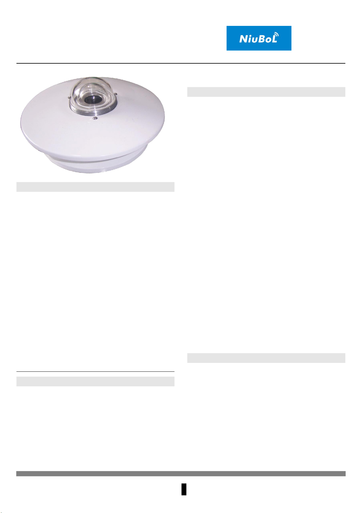
Product introduction
The TBQ total radiation sensor adopts the principle
of thermoelectric induction and is used in conjunction
with various radiation recorders or radiation
ammeters to accurately measure the sun's TBQ total
radiation, reflected radiation, scattered radiation,
infrared radiation, visible light, ultraviolet radiation,
long-wave radiation, etc.
The core sensing element of the watch adopts a
wire-wound electroplating multi-contact thermopile,
and its surface is coated with a black coating with
high absorption rate. The hot junction is on the
sensing surface, while the cold junction is located in
the body, and the cold and hot junctions generate a
thermoelectric potential. In the linear range, the
output signal is proportional to the solar irradiance.
The double-layer glass cover is to reduce the
influence of air convection on the pyranometer, and
the inner cover is designed to cut off the infrared
radiation of the outer cover itself.
Use
The meter is used to measure the total solar TBQ
radiation in the spectral range of 0.3-3μm, and it can
also be used to measure the solar radiation incident
on the inclined plane. If the sensing surface is facing
down, the reflected radiation can be measured, and
the shading ring can be used to measure the scattered
radiation. Therefore, it can be widely used in solar
energy utilization, meteorology, agriculture, aging of
building materials and air pollution to measure solar
radiation energy.
Technical Parameters
Sensitivity: 7~14μV/w.m-2
Spectral range: 0.3-3μm
Measuring range: 0~2000W/m2
Power supply mode: □ DC 5V
□ DC 12V
□ DC 24V
□Other
Output form: □ Current: 4~20mA
□ Voltage: 0~2.5V
□ Voltage: 0~5V
□ Voltage: 0~20mV
□ RS485
□ Other
Instrument cable length: □ Standard: 2.5 meters
□□Other
Response time: ≤35 seconds (99%)
Internal resistance: about 350Ω
Annual stability: ≤±2%
Cosine response: ≤7% (when the sun altitude angle is
10°)
Azimuth response error: ≤5% (when the sun
elevation angle is 10°)
Temperature characteristics: ±2% (-10℃~+40℃)
Working environment temperature: -40℃~+50℃
Nonlinearity: ≤2%
Weight: 2.5kg
Calculation formula
Voltage type (0~20mV):
F=(V/sensitivity coefficient)*1000
F: Radiation value, unit W/m2, V: output voltage,
unit mV, sensitivity coefficient Check TBQ test report
Voltage type (0~5V):
F=(V/5)*2000
F: radiation value, unit W/m2, V: output voltage, unit
V, radiation test range 0~2000W/m2
Current type (4~20mA):
F=(I-4)/16*2000
NBL-W-HPRS/Total radiation sensor V3.0
Changsha Zoko-Link Technology Co., Ltd.
2
F: radiation value, unit W/m2, I: output current, unit
mA, radiation test range 0~2000W/m2
Connection method
(1) If equipped with the collector produced by our
company, directly connect the sensor to the
corresponding interface on the collector using
the sensor cable.
(2) If the transmitter is purchased separately, the
corresponding line sequences are:
Line color
output signal
Voltage
Current
Communication
s
Red
+
+
+
Black
(Green)
-
-
-
Yellow
Voltage
signal
Current
Signal
A+/TX
Blue
B-/RX
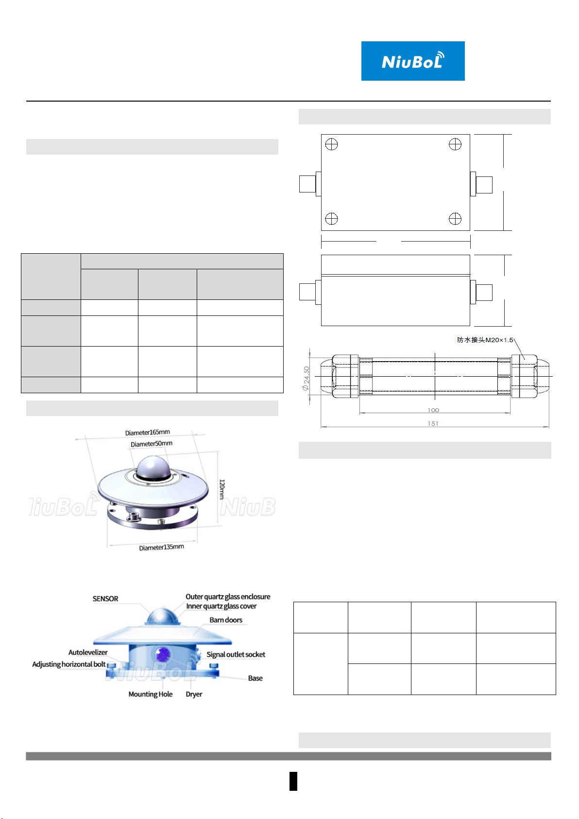
External structure
□ TBQ Total Radiation Dimensions
□ TBQ Total Radiation Functional diagram
Dimensions
6 6 m m
49 m m
9 8 m m
installation and use
The sensor should be installed in an open area
without any obstacles above the sensing surface.
Then, align the pyranometer cable plug to the north,
adjust the horizontal position, fix it firmly, and then
connect the TBQ pyranometer output cable with the
acquisition device to observe. It's a good idea to have
the cables securely fastened to the mount to reduce
breaks or intermittent interruptions on windy days.
Wiring Instructions:
Name
Line Color
Description
of output
Corresponding
plug pins
TBQ
total
radiation
sensor
Red
+
1 pin of the
four-core plug
Black
(Green)
-
2 pins of the
four-pin plug
MODBUS-RTU Communication Protocol

NBL-W-HPRS/Total radiation sensor V3.0
Changsha Zoko-Link Technology Co., Ltd.
3
ⅠSerial port format
Data bits 8 bits
Stop bit 1 or 2 bits
Check Digit None
Baud rate 9600 The interval between two
communications is at least 1000ms
ⅡCommunication format
[1] Write device address
Send: 00 10 Address CRC (5 bytes)
Returns: 00 10 CRC (4 bytes)
Instructions: 1. The address bit of the read/write
address command must be 00.
2. Address is 1 byte, the range is 0-255.
For example: send 00 10 01 BD C0
return 00 10 00 7C
[2] Read device address
Send: 00 20 CRC (4 bytes)
Returns: 00 20 Address CRC (5 bytes)
Description: Address is 1 byte, the range is 0-255
For example: send 00 20 00 68
Return 00 20 01 A9 C0
[3] Read real-time data
Send: Address 03 00 00 00 01 XX XX
Description: As shown in the figure below:
Code
Functional Definition
Remark
Address
Station number
(address)
03
Function code
00 00
Start address
00 01
Read points
XX XX
CRC Check code, low
front and high back
Return: Address 03 02 XX XX XX XX
illustrate:
Code
Functional Definition
Remark
Address
Station number
(address)
03
Function code
02
Read unit bytes
XX XX
Data (front high and
back low)
hex
XX XX
CRC Check code
Steps to calculate CRC code:
1. The preset 16-bit register is hexadecimal FFFF
(that is, all 1s). Call this register the CRC register;
2. XOR the first 8-bit data with the lower bits of the
16-bit CRC register, and place the result in the CRC
register;
3. Shift the contents of the register one bit to the right
(toward the lower bit), fill the highest bit with 0, and
check the lowest bit;
4. If the lowest bit is 0: repeat step 3 (shift again)
If the lowest bit is 1: XOR the CRC register with
the polynomial A001 (1010 0000 0000 0001);
5. Repeat steps 3 and 4 until the right shift is
performed 8 times, so that the entire 8-bit data is
processed;
6. Repeat steps 2 to 5 to process the next 8-bit data;
7. The final CRC register is the CRC code;
8. When the CRC result is put into the information
frame, the high and low bits are exchanged, and the
low bits are first.
RS485 circuit
Instruction manual
Wire the sensor according to the instructions in the

NBL-W-HPRS/Total radiation sensor V3.0
Changsha Zoko-Link Technology Co., Ltd.
4
wiring method, then place it at the position where the
radiation is to be measured, turn on the power supply
and the switch of the collector, and the radiation
value at the measurement point can be obtained.
Notice
1. Please check whether the packaging is in good
condition, and check whether the product model is
consistent with the selection;
2. Do not connect with live power. After the wiring is
completed and checked, the power can be turned on;
3. The length of the sensor line will affect the output
signal of the product. Do not arbitrarily change the
components or wires that have been soldered when
the product leaves the factory. If you need to change
it, please contact the manufacturer;
4. The sensor is a precision device, please do not
disassemble it by yourself, or touch the surface of the
sensor with sharp objects or corrosive liquid, so as
not to damage the product;
5. Please keep the verification certificate and
qualification certificate, and return it together with
the product during maintenance.
Trouble clearing
1. During the analog output, the displayed value is
obviously too large/small. Please check whether there
is dirt or debris on the sensor port; if so, wipe it off
with a clean rag;
2. During analog output, the display device indicates
that the value is 0 or not within the range. The
collector may not be able to obtain the information
correctly due to the wiring problem, please check
whether the wiring is correct and firm;
3. If not for the above reasons, please contact the
manufacturer.
Product Maintenance
1. It is not allowed to dismantle or loosen the filter
cover, so as not to affect the measurement accuracy.
Be especially careful when opening or closing the
metal cap, as the filter cover is expensive and fragile.
The filter cover should be kept clean, often wipe with
a soft cloth or fur;
2. Water should not enter the filter cover, and there
should be no condensation in the cover. Always
check whether the desiccant in the dryer becomes
damp (from blue to red or white), otherwise it should
be replaced in time or the desiccant should be dried in
the oven to make it turn back to blue before use;
3. The TBQ total radiation sensor has good
waterproof performance. Generally, it can not be
covered for a short time or when the precipitation is
small. However, if there is heavy rain (snow, ice, etc.)
or rain for a long time, in order to protect the
pyranometer, the observer should put a cover on it
according to the specific situation, and open the cover
after the rain stops;
4. The TBQ total radiation sensor has been used for
more than two years, and its sensitivity must be
re-calibrated by the manufacturer or the measurement
department.
Service commitment
TBQ total radiation sensor from the date of delivery
within 1 year due to quality problems caused by
non-human factors, the production unit is responsible
for free maintenance or replacement. If the user is
artificially damaged, the cost will be charged, but the
maintenance fee will not be charged. In addition, our
company solemnly promises to be responsible for
life-long maintenance of factory products.
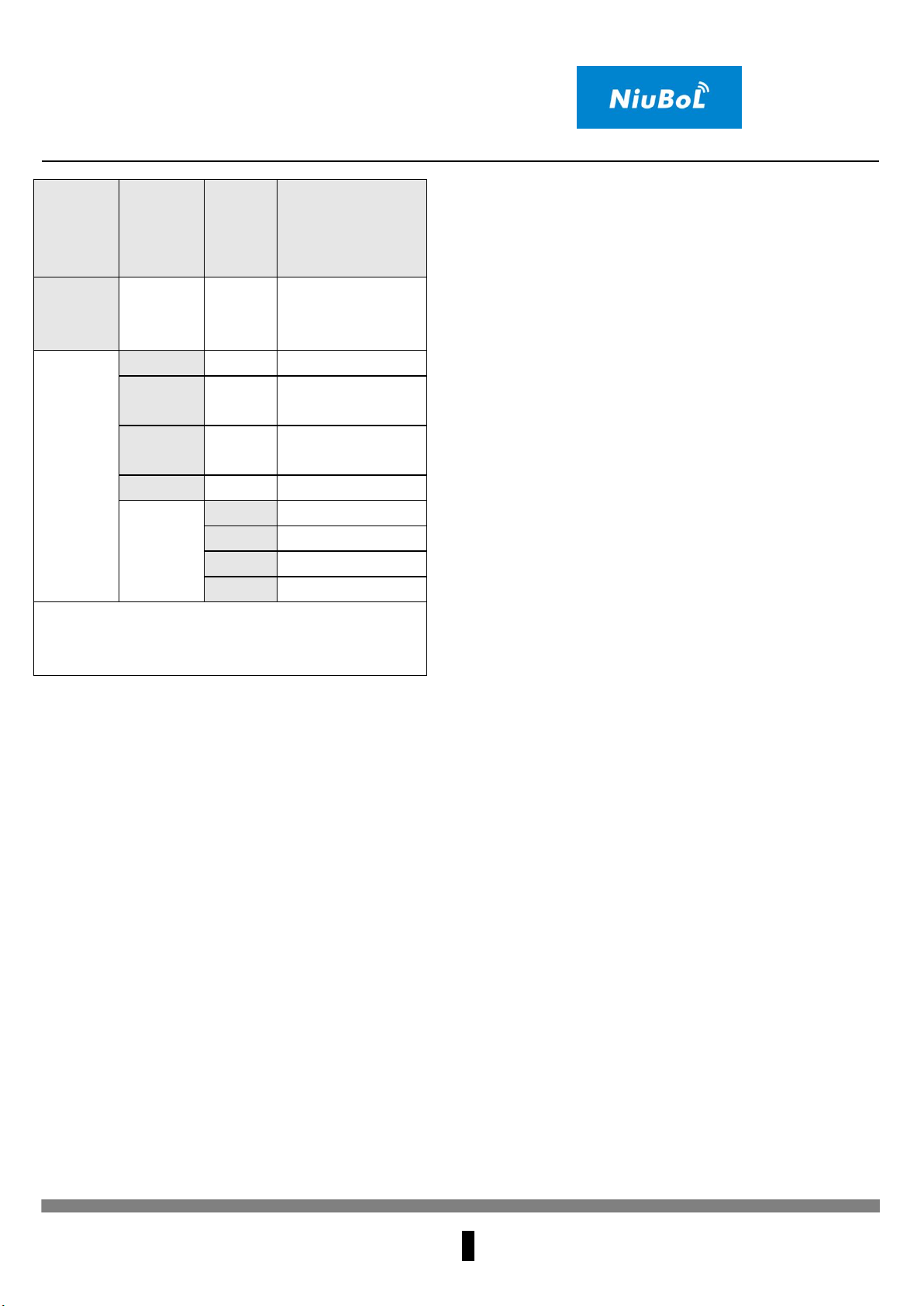
Selection table
NBL-W-HPRS/Total radiation sensor V3.0
Changsha Zoko-Link Technology Co., Ltd.
5
No.
Power
supply
method
output
signal
Explanation
NBL-W-
HPRS
TBQ Total
Radiation Sensor
(Transmitter)
5V-
5V Power supply
12V-
12V Power
supply
24V-
24V Power
supply
Z-
No
V
0-5V
A1
4-20mA
W2-
RS485
V3-
0-20mV
For example: NBL-W-HPRS-12V-A1: TBQ total
radiation sensor 12V power supply, 4-20mA
current signal output


