Nivetec UNICONT PMM-500 Owner's manual

pmm5111a0600p_01
1 / 32
UNICONT
PMM-500
Universal process controller and
display unit
User's and Programming manual
1 edition
st

2 / 32
pmm5111a0600p_01
TABLE OF CONTENTS
1. GENERAL DESCRIPTION........................................................................................................................3
2. ORDER CODE...........................................................................................................................................4
3. TECHNICAL DATA ...................................................................................................................................5
4. DIMENSIONS ............................................................................................................................................6
5. MOUNTING ...............................................................................................................................................6
6. WIRING......................................................................................................................................................6
6.1 WIRING INSTRUCTIONS ..........................................................................................................................6
6.2 WIRING CHART OF THE OUTPUT VERSIONS ...............................................................................................7
7. FRONT PANEL, KEYPAD, DISPLAYS ....................................................................................................8
8. ERROR MESSAGES AND INDICATIONS ...............................................................................................9
9. PROGRAMMING SEQUENCE................................................................................................................10
9.1 POWERING UP FOR THE FIRST TIME .......................................................................................................10
9.2 SELECT MODE ....................................................................................................................................10
9.2.1 Mode Selection sequence for programming............................................................................10
9.2.2 Unlock code.............................................................................................................................11
10. OPERATION MODES, PROGRAMMING .............................................................................................11
10.1 INFORMATION MODE..........................................................................................................................12
10.2 CONFIGURATION MODE......................................................................................................................12
10.3 SET-UP MODE...................................................................................................................................21
10.4 AUTO-TUNING (AT) MODE .................................................................................................................25
10.5 MANUAL SETTING OF PID PARAMETERS...............................................................................................25
10.6 MANUAL FINE TUNING OF PID PARAMETERS ........................................................................................26
10.7 OPERATOR MODE .............................................................................................................................27
10.7.1 Display modes.......................................................................................................................27
10.7.2 Manual Mode.........................................................................................................................29
11. COMMUNICATION................................................................................................................................29
11.1 GENERAL DATA .................................................................................................................................29
11.2 MODBUS COMMUNICATION .................................................................................................................30
11.3 COMMUNICATION PARAMETERS ..........................................................................................................30
11.3.1 Bit Parameters.......................................................................................................................30
11.3.2 Word Parameters ..................................................................................................................31

pmm5111a0600p_01
3 / 32
Thank you for choosing a NIVELCO instrument.
We are sure that you will be satisfied throughout its use!
1. GENERAL DESCRIPTION
The UNICONT PMM-500 universal display and controller instruments are 1/16 DIN (48x48mm) size, panel
mountable, modern, easy of use microprocessor based devices supporting versatile functions. EEPROM
memory ensures data- and program protection during power outages.
The universal input can be connected with wide range of temperature sensors (Pt-100 RTD-s and most type
of thermocouples), or standard analogue current and voltage signals (mA, mV, V).
The instrument operates its control outputs in accordance to selected control algorithm generated from the
measured input values of various physical parameters.
The control algorithm can be ON-OFF, or PID, therefore it can provide differential control, or can realize
multiple control characteristics.
Using the Auto Tuning mode, the instrument provides optimal settings without entering any P-I-D
parameters.
The controller has multiple outputs: relay, SSR-driver, analogue current-, or voltage output, RS485
communication. The modular structure provides wide selection of output variations. In accordance to the
mechanical structure of the output boards (plug-in PCB-s) there is a possibility to order special (differing
from the standard) variations.
Inputs Outputs
Thermocouple
Voltage signal
PMM-500
Universal
controller
Relay
SSR driver
RS485 communication
Power supply for
transmitters
ON-OFF
PID
Heat / Cool
operation
Manual
mode
Controls
The RS485 Modbus RTU serial output provides digital communication interface with PC and remote
programming possibility.
Some models have 24V DC output performing power supply for transmitters.
The large bi-coloured 2-line, 7-segmented, 4-digit LED display provides easy reading even from far distance.
It indicates the Process (PV) and a Set-point (SV) Value, as well the programming steps or other settings.
Operation modes and alarm signals are indicated with LED-s. The 4 push-buttons provide easy
programming.

4 / 32
pmm5111a0600p_01
2. ORDER CODE
UNICONT PMM-500 series:
UNICONT PMM-5 –*
INPUT CODE POWER SUPPLY CODE
Universal 100-240 V AC 1
(sensor or analogue)
1 20-48 V AC
22-65 V DC 2
OUTPUT* CODE
R1, R2, analogue OUT 1 OUTPUT DESCRIPTION
R1, R2, Ut2 R1, R2, R3 SPDT relay outputs
R1, analogue OUT, Ut3analogue OUT Analogue current- or voltage outputs
R1, R2, R3 4 SSR1, SSR2 Solid State Relay driver output
SSR1, SSR2, analogue OUT 5 UtTransmitter power supply 24 V DC/ 22 mA
SSR1, SSR2, Ut6 RS485 Serial communication line
SSR1, analogue OUT, Ut7
SSR1, R1, analogue OUT 8 Accessories:
R1, R2, analogue OUT, RS485 A NAME ORDER CODE
R1, R2, Ut, RS485 B Mounting accessory pmm5111m00001
R1, analogue OUT, Ut, RS485 C Front plate sealing pmm5111m00002
R1, R2, R3, RS485 D Front plate size adapter
SSR1,SSR2, analogue OUT, RS485 E from 96x48 mm cut-off PAM-500-0
SSR1, SSR2, Ut, RS485 Fsize to 48x48 mm
SSR1, analogue OUT, Ut, RS485 G
SSR1, R1, analogue OUT, RS485 H
* Special output versions differing from the above code-variations are available to order.

pmm5111a0600p_01
5 / 32
3. TECHNICAL DATA
Type PMM-5--
Pt100 RTD: -199 ºC...+800 ºC
Thermocouple: J, T, K, L, N, B, R, S, C, Pt Rh
-240 ºC...+2320 ºC
Current: (DC) 4-20 mA, 0-20 mA
Sensor,
or analogue input
Voltage: (DC) 0-50 mV, 10-50 mV,
0-5 V, 1-5 V, 0-10 V, 2-10 V
Input resistance
Pt100 RTD: >10 MOhm,
Current input (20 mA): 5 Ohm
Voltage input (10 V): 47 kOhm
Input
Other data
Input Sampling rate: 4 / sec
Digital Input Filter time constant: 0.5...100 sec
Pt100 Sensor Current: 150 µA
Isolated from all outputs (except SSR driver)
Relay Max. 3 pcs., SPDT (Single pole double throw) 240 V AC, 2A, AC11
SSR Max. 2 pcs., SSR (Solid State Relay) driver, 0-10 V DC / 20 mA
Analogue DC
4-20 mA, 0-20 mA / 500 Ohm max.
0-5 V, 0-10 V, 2-10 V/500 Ohm min.
Short-circuit protected
Accuracy: ±0.25 %
Reinforced safety isolation from the input and other outputs
Transmitter power
supply
19-28 V DC not regulated, Nominal value: 24 V DC / 22mA,
Reinforced safety isolation from the input and other outputs
Outputs
Serial communication RS485 MODBUS RTU, Address range: 1-255, Bit rate: 1200-19200 Baud
Features Operation range Resolution
Proportional Bands (P) 0.5-999.9% 0.1 %
Derivative Time Constant (D) 0 - 100 min 1 sec
Integral Time Constant (I) 1 sec - 100 min 1 sec
Cycle Times 0.5 sec - 512 sec binary steps
ON/OFF Differential 0.1% - 10 % of input span 0.1 %
Controls:
ON / OFF
P, PD, PI, PID, Dual PID
AT
AUTO / MANUAL
Cooling / Heating Deadband/Overlap -20 % ...+20 % of input span 0.1 %
Process Value (PV): 4 digit, red, height of characters: 10 mm7-segment LED
display Set Value (SV): 4 digit, green, height of characters: 8 mm
Indication
LED
Operation modes:
Select mode, configuration
Automatic Tune
Alarms
Over-range indication
Under-range indication
Configuration With press buttons of the front panel from -1999 to +9999 range
Measurement accuracy ±0.1% of range ±1LSD, Thermocouple: ±0.1% of full range span ±1LSD
Linearization accuracy Better than ±0.2°C any point, any 0.1°C range ( ±0.05°C typical). Better than ±0.5°C any point,
any 1 °C range
Temperature stability 0.01% of range/°C change in ambient temperature
Sensor break protection Process Control outputs turn OFF within two seconds
In case of analogue input: applicable for 4 to 20mA, 1 to 5V and 2 to 10V ranges only
Cold junction compensation > ±1 ºC
Wire compensation 3-wire Pt100, automatic
100-240 V AC 50/60 Hz 7.5 VA
Power supply 20-48 V AC 50/60 HZ 7.5 VA; 22-65 V DC 5 W
Electrical connection Screw type terminals
Memory protection Data stored in EEPROM
Electrical protection Class II.
Ingress protection Front panel: IP66 Back panel: IP20
Ambient temperature 0 ºC…+55 ºC
Storage temperature -20 º…+80 ºC
Relative humidity Max. 85%
Dimensions 48 x 48 x 110 mm
Mass ~0.25 kg

6 / 32
pmm5111a0600p_01
4. DIMENSIONS
The unit can be mounted into a
suitable 1/16DIN (48x48 mm) cut-
out place. Insertion length of the
unit is 110mm, the additional
dimensions can be seen on the
drawing below.
48
48 10 110
5. MOUNTING
The unit can be mounted with the help of the
attached mounting accessory to the suitable cut-out
hole. Be careful with the sealing, which provides
proper sealing from the front panel. Suitable
distances between multiple units should be taken
into consideration.
The cut-out dimensions in case of single, or multiple
units should be the following, and width of the
mounting-plate is Lv=3-9 mm.
Using the optional PAM-500-0 front plate size
adapter the 48x48mm sized unit can be mounted to
an existing 96x48mm cut-out hole. In case of using
the front plate size adapter, the width of the
mounting-plate is Lv=3-5 mm
62
55
45
+0,5
+0,2
45
+0,5
+0,2
6. WIRING
6.1 WIRING INSTRUCTIONS
POWER SUPPLY
PMM-5□□ -1 PMM-5□□ -2
100-240 V AC 20-48 V AC
22-65 V DC
T1A T365 mA
Notes:
Connect the line voltage (live and neutral) as illustrated via a
two-pole isolating switch (preferably located near the equipment)
and an anti-surge fuse.
All analogue and communication signals must use shielded
cable. The shield should be grounded at one end only.
Two wire RTDs leads should be less than 3 metres long,
resistive leg and the common legs of the RTD (4-5 points) should
be connected.
Four wire RTDs can be used, provided that the fourth wire is left
unconnected.
+
-
Fuse
Power supply
OUT A
OUT 2.
OUT 3.
Thermo-
couple
Analogue
mA V/mV
IN
+
-
+
+
--
-
1
2
3
4
5
6
7
8
9
10
11
12
16 17 18
13 14 15
TOP
OUT 1.
Pt100

pmm5111a0600p_01
7 / 32
6.2 WIRING CHART OF THE OUTPUT VERSIONS
Outputs
OUT1 OUT2 OUT3 OUTA
Type
1
2
3
13
14
15
16
17
18
11
12
PMM-511-□
R1
N
O
N
C
C
R2
N
O
N
C
C
Analogue
PMM-512-□
R1
N
O
N
C
C
R2
N
O
N
C
C
24V DC / 22mA
PMM-513-□
R1
N
O
N
C
C
Analogue
24V DC / 22mA
PMM-514-□
R1
N
O
N
C
C
R2
N
O
N
C
C
R3
NON
C
C
PMM-515-□
SSR1
10V DC / 20mA
SSR2
10V DC / 20mA
Analogue
PMM-516-□SSR1
10V DC / 20mA
SSR2
10V DC / 20mA
24V DC / 22mA
PMM-517-□SSR1
10V DC / 20mA
Analogue
24V DC / 22mA
PMM-518-□
SSR1
10V DC / 20mA
R2
N
O
N
C
C
Analogue
RS485
PMM-51A-□
R1
N
O
N
C
C
R2
N
O
N
C
C
Analogue
B A
RS485
PMM-51B-□
R1
N
O
N
C
C
R2
N
O
N
C
C
24V DC / 22mA
B A
RS485
PMM-51C-□
R1
N
O
N
C
C
Analogue
24V DC / 22mA
B A
RS485
PMM-51D-□
R1
N
O
N
C
C
R2
N
O
N
C
C
R3
NON
C
C
B A
RS485
PMM-51E-□SSR1
10V DC / 20mA
SSR2
10V DC / 20mA
Analogue
B A
RS485
PMM-51F-□SSR1
10V DC / 20mA
SSR2
10V DC / 20mA
24V DC / 22mA
B A
RS485
PMM-51G-□
SSR1
10V DC / 20mA
Analogue
24V DC / 22mA
B A
RS485
PMM-51H-□
SSR1
10V DC / 20mA
R2
NO N
C
C
Analogue
B A
8 / 32
pmm5111a0600p_01
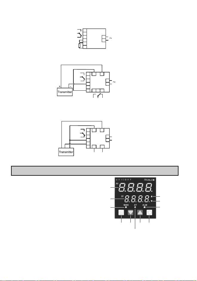
Wiring examples:
2-wire Pt 100 RTD, 1 relay output.
1
2
3
4
5
6
9
10 100-240V AC
Pt100
NO
NC
C
OUT 1.
2-wire 4-20 mA transmitter, power supply for transmitter, 2 pcs. relay output.
1
2
3
4
5
6
9
10
16 18
13
14 15
OUT 1. NO
NC
C
100-240V AC
NO NC
C
24VDC
+
-
+
-
4-20mA
OUT 2.
OUT 3.
3-wire voltage output transmitter, power supply for transmitter, 1 relay output, 1 analogue output.
1
2
3
4
5
6
9
10
16 18
13 15
NO
NC
C
pl. 22- 65V DC
24VDC
+
-
+
-
U
-
+
-
+
OUT
+
-
Analogue OUT
OUT 2.
OUT 1.
OUT 3.
7. FRONT PANEL, KEYPAD, DISPLAYS
The 7-segmented displays show the measured and
set process values (Process Value-PV, Set Value-
SV) in normal operation, and show text signals and
values in accordance to the actual state of
programming and configuration. With the 4 push-
buttons the menu-system can be handled and
programming can be performed.
Process Value
Set Value
Manual mode
Auto Tuning
Toggle between
Automatic /
Manual control
and acknowledge
Down Up Function
Primary output
Secondary output
Alarm indication

pmm5111a0600p_01
9 / 32
Operation
LED LIGHTS FLASHES
MAN Setup mode Manual mode
Auto tuning mode
AT Self-Tune mode Pre-Tune mode
ALM - Alarm condition is present
▲
For Current Proportioned outputs, ON indicates
primary power is >0%
It turns ON when the stored Max. PV value is
displayed on indicators
FLASHES in unison with Time Proportioning
Primary outputs
▼
For Current Proportioned outputs, ON secondary
power is >0%
It turns ON when the stored Min. PV value is
displayed on indicators
FLASHES in unison with Time Proportioning
Secondary outputs,
After powering ON the unit performs an automatic self-test and flashes all front-plate LEDs for a moment. At
first turning ON, or after replacing an output module indication can be seen on the
display, which means that the unit should be configured in Configuration Mode (see 9.1, 10.2. points).
In all other cases after the self-test the unit returns to normal operation mode.
8. ERROR MESSAGES AND INDICATIONS
ERROR DESCRIPTION PV DISPLAY SV DISPLAY
Configuration & Setup is required at first turn ON or if
hardware configuration changed!
Press button to enter configuration mode, then press ,
or button to unlock code number, then press button to
proceed. Configuration should be completed according to the
configuration menu points.
Input more than 5% over-range 1 Normal display
Input more than 5% under-range 2 Normal display
Sensor Break. Break detected in the input sensor or wiring Normal display
OUTPUT 1 error
OUTPUT 2 error
OUTPUT 3 error
OUTPUT A error
1 If the PV display exceeds 9999 before 5% over-range is reached, an over-range indication is given.
2Indicators will allow up to 10% under-range on non-zero based Linear ranges. If the PV display is less than
-1999 before the 5% under-range is reached, an under-range indication is given.
10 / 32
pmm5111a0600p_01
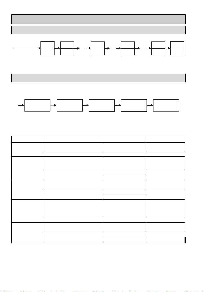
9. PROGRAMMING SEQUENCE
9.1 POWERING UP FOR THE FIRST TIME
Self-test
First turn ON
Turn ON
after replacing
an output
module
Automatic
hardware test
Entering
unlock code
Selecting the value of
unclock code
Configuration
menu
Normal
operation
Wait 2 minutes
Self-test
9.2 SELECT MODE
9.2.1 MODE SELECTION SEQUENCE FOR PROGRAMMING
Information
mode
Configuration
mode
Set-up
mode
Auto-tuning
mode
Operator
mode
Hold down button and press button in any mode to enter Select Mode. Once in Select Mode, press
or to select the required mode, then press to enter the chosen mode.
MODE FUNCTION PV DISPLAY SV DISPLAY
The Default Mode on power up used
for normal operation
Operator mode
Unlock code none
Used to tailor the instrument to the
application, adjustment of tuning
terms etc.
Set-up mode
Unlock code Default value: 5
Used to configure the instrument for
first time use or on re-installation.
Configuration
mode Unlock code Default value: 5
Used to check the hardware, firmware
and
manufacturing information of the
instrument
Production
Information mode
Unlock code none
Used to invoke pre-tune or self-tune
on controllers.
Auto Tuning mode
Unlock code Default value: O
If there is no key activity for 2 minutes the controller automatically returns to operator mode!

pmm5111a0600p_01
11 / 32
9.2.2 UNLOCK CODE
To enter a required menu point press button then select the corresponding unlock code with and
buttons. This procedure can prevent unauthorised entry to Configuration, Setup and Automatic Tuning
modes. Entering an incorrect unlock code will result to return to Select Mode. The value of the lock codes
only can be changed from within the modes that they apply to.
In the event that a lock code is not known or forgotten, the instrument lock code values can be seen in the
lock code view. In this view the codes are read only, the codes can be changed from the mode to which they
apply.
Turn OFF the device. Press and together whilst the instrument is powering up until the display is
shown. Once in this mode press to step between lock codes.
LOCK CODE NAME PV DISPLAY SV DISPLAY
Configuration Lock Code Max. 4 digit value, DEFAULT VALUE: 5
Setup Lock Code Max. 4 digit value, DEFAULT VALUE: 5
Automatic Tune Lock Code Max. 4 digit value, DEFAULT VALUE: 0
If there is no key activity for 2 minutes the controller automatically returns to operator mode!
10. OPERATION MODES, PROGRAMMING
Self
Tes t
+
Turn ON
+
Operation mode Normal operation
Normal
operation
Automatic
hardware test
Entering unlock code
Entering
set-up
mode
+
Set-up
mode
+
+
Entering
unlock code
Toggle
menu points
Entering
configuration
mode
-Entering an incorrect unlock code
results in a return to Select Mode.
-If there is no key activity for 2 minutes
the controller autamtically returns to
normal operation.
Warning!
Configuration
mode
To gg l e
menu points
Entering
information
mode
To gg l e
menu points
Information
mode
+
To gg l e
menu points
Entering
auto-tuning
mode
Entering
unlock code
Auto-tuning
mode

12 / 32
pmm5111a0600p_01
10.1 INFORMATION MODE
This mode describes the instrument and the options fitted to it. It is advised to start Select Mode procedure
with this point because toggling in the menu, hardware configuration, manufacturing data can be seen about
the given instrument.
+
+
Toggle menu points
Exit from Select Mode
Parameters are read only!
If there is no key activity for 2 minutes the controller automatically returns to operator mode!
PARAMETER POSSIBLE VALUES PV DISPLAY SV DISPLAY
Input type Universal input
No option fitted
R1 Relay
Option 1 module type
SSR1 drive
No option fitted
R2 Relay
SSR2 drive
Option 2 module type
Linear voltage / current output
No option fitted
R3 Relay
Linear voltage / current output
Option 3 module type
24V Transmitter power supply
No option fitted
Auxiliary option A module type RS485
Type number 4 characters
Firmware Issue number 2 characters
Product Rev Level Interior code 4 characters
Date of manufacture Interior code 4 characters
Serial number Interior code
4 characters
4 characters
4 characters
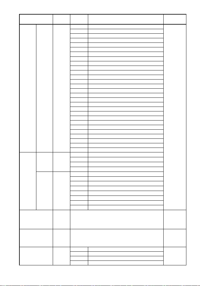
10.2 CONFIGURATION MODE
This mode is normally used only when the instrument is configured for the first time or when a major change
is made to the instruments characteristics.The Configuration Mode parameters must be set as required
before adjusting parameters in Setup Mode, or attempting to use the instrument in an application.
Navigating in Configuration Mode
+
Select
mode
Toggle to the
next parameter
+
Return to
Select Mode
Configuration
mode
Entering unlock code
Default value: 5
Entering configuration
mode menu
Default value:
Toggle
menupoints
Setting the value of the
parameter as required Accept
Caution:
Entering an incorrect unlock code will result to return to Select Mode. Only parameters that are
applicable to the hardware options chosen will be displayed.
Once the value is changed, the display will flash to indicate that confirmation of the change is required.
The value will revert back if not confirmed within 10 seconds.
If there is no key activity for 2 minutes the controller automatically returns to operator mode!
pmm5111a0600p_01
13 / 32
PARAMETER SV-
DISPLAY
PV-
DISPLAY ADJUSTMENT RANGE DEFAULT
VALUE
B tip. 100…1824 °C
B tip. 211…3315 °F
C tip. 0…2320 °C
C tip. 32…4208 °F
J tip. -200…120 °C
J tip.-328…2192 ° F
J tip. -188,8…537,7 °C
J tip. -199,9…999,9 °F
K tip.-240…1373 °C
K tip. -400…2503 °F
K tip. -128,8…537,7 °C
K tip. -199,9…999,9 °F
L tip. 0…762 °C
L tip. 32…1403 °F
L tip.0,0…537,7 °C
L tip. 32,0…999,9 °F
N tip. 0…1399 °C
N tip. 32…2551 °F
R tip. 0…1759 °C
R tip.32…3198 °F
S tip. 0…1762 °C
S tip. 32…3204 °F
T tip. -240…400 °C
T tip. -400…752 ° F
T tip. -128,8…400,0 °C
T tip. -199,9…752,0 °F
PtRh tip. 0…1850 °C
Input type and
Range
Thermocouple
PtRh tip. 32…3362 °F
Pt100: -199…800 °C
Pt100: -328…1472 °F
Pt100: -128,8…537,7 °C
Pt100
Pt100: -199,9…999,9 °F
0-20 mA DC
4-20 mA DC
0-50 mV DC
10-50 mV DC
0-5V DC
1-5 V DC
0-10 V DC
Input type and
Range
Analogue
2-10 V DC
Scale Range
Upper Limit
Scale Range Lower Limit +100 to Range Max
Between -1999…+9999
Linear inputs
= 1000 (°C/°F
inputs = max
range)
Scale Range
Lower Limit
Range Min. to Scale range Upper Limit -100
Between -1999…+9999 Linear =
(°C/°F = min
range):
No decimal point
XXX.X
XX.XX
Decimal point position
(Only for analogue
input)
X.XXX

14 / 32
pmm5111a0600p_01
PARAMETER SV-
DISPLAY
PV-
DISPLAY ADJUSTMENT RANGE DEFAULT
VALUE
Single outputs can drive the PV in one direction only (e.g.
heat only, cool only, increase humidity etc)
Control Type
Dual outputs can force the PV to increase or decrease
(e.g heat & cool, humidify and dehumidify etc)
Reverse action is typically used with heating applications;
On-Off reverse outputs will turn off when the process
variable exceeds setpoint. Proportional reverse outputs
will decrease the percentage of output as the process
value increases within the proportional band. The
Secondary Output will be direct whenever the Primary
Output is selected as reverse.
Primary Output
Control Action
Direct action is typically used with cooling applications;
On-Off direct outputs will turn on when the process
variable exceeds setpoint. Proportional direct outputs will
increase the percentage of output as the process value
increases within the proportional band. The Secondary
Output will be reverse whenever the Primary Output is
selected as direct.
Process High Alarm
Reverse action
OFF
ON
OFF ON
OUT
ALM
Alarm PV
Direct action
OFF
ON
OFF ON
OUT
ALM
Alarm PV
Alarm 1 Type
Process Low Alarm
Reverse action
OFF
ON
OFF
ON
OUT
ALM
Alarm PV
Direct action
OFF
ON
OFF
ON
OUT
ALM
Alarm PV

pmm5111a0600p_01
15 / 32
PARAMETER SV-
DISPLAY
PV-
DISPLAY ADJUSTMENT RANGE DEFAULT
VALUE
Deviation Alarm
Up
Reverse action
OFF
ON
OFF ON
OUT
ALM
Alarm
PV
+
Direct action
OFF ON
OFF ON
OUT
ALM
Alarm
PV
+
Down
Reverse action
OFF
ON
OFF
ON
OUT
ALM
Alarm PV
-
Direct action
OFF
ON
OFF
ON
OUT
ALM
Alarm PV
-
Band Alarm
Reverse action
OFF
ON
OFF
ON
OUT
ALM
Alarm
PV
-
OFF
ON
+
==
Direct action
OFF
ON
OFF
ON
OUT
ALM
PV
Alarm
-+
==
ON
ON
No alarm
Process High
Alarm 1 value
Only visible when
= set
Parameter is repeated
in Set-up Mode
Range Min. to Range Max. Range
Max.
Process Low
Alarm 1 value
Only visible when
= set
Parameter is repeated
in Set-up Mode
Range Min. to Range Max. Range
Min.

16 / 32
pmm5111a0600p_01
PARAMETER SV-
DISPLAY
PV-
DISPLAY ADJUSTMENT RANGE DEFAULT
VALUE
Deviation
Alarm 1 Value
Only visible when
= set
Parameter is repeated
in Set-up Mode
±span from setpoint 5
Band Alarm 1 Value
Only visible when
= set
Parameter is repeated
in Set-up Mode
1 LSD to full span from setpoint 5
Alarm 1 Hysteresis
Parameter is repeated
in Set-up Mode
Up to
100% of
span
Alarm hysteresis
Process High Alarm or Deviation Alarm
OFF ON OFF
Alarm Hysteresis
Value
Alarm Value
or Deviation
Alarm value
PV
Process Low Alarm or Deviation Alarm
PV OFF ON OFF
Alarm or
Deviation value
Alarm Hysteresis
Value
Band Alarm
Setpoint
OFF OFF
ON ON OFF
PV
Alarm
band
Alarm Hysteresis
Value
Alarm Hysteresis
Value
1
As for Alarm 1.
As for Alarm 1.
As for Alarm 1.
As for Alarm 1.
Alarm 2 Type
As for Alarm 1.
Process High
Alarm 2 Value
Only visible when
= set
Parameter is repeated
in Set-up Mode
Range Min. to Range Max Range
max.
Process Low
Alarm 2 Value
Only visible when
= set
Parameter is repeated
in Set-up Mode
Range Min. to Range Max Range
min.

pmm5111a0600p_01
17 / 32
PARAMETER SV-
DISPLAY
PV-
DISPLAY ADJUSTMENT RANGE DEFAULT
VALUE
Deviation
Alarm 2 Value
Only visible when
= set
Parameter is repeated
in Set-up Mode
±span from setpoint 5
Band Alarm 2 Value
Only visible when
= set
Parameter is repeated
in Set-up Mode
1 LSD to full span from setpoint 5
Alarm 2
Hysteresis
Parameter is repeated
in Set-up Mode
1 LSD to
100% of
span (in
display
units) on
“safe” side
of alarm
point
As for Alarm 1. 1
Disabled:
Loop Alarm Enable
Enabled:
Loop Alarm
A loop alarm is a special alarm, which detects faults in
the control feedback loop, by continuously monitoring
process variable response to the control output(s). The
loop alarm can be tied to any suitable output. When
enabled, the loop alarm repeatedly checks if the control
output(s) are at the maximum or minimum limit. If an
output is at the limit, an internal timer is started:
thereafter, if the high output has not caused the process
variable to be corrected by a predetermined amount 'V'
after time 'T' has elapsed, the loop alarm becomes
active. Subsequently, the loop alarm mode repeatedly
checks the process variable and the control output(s).
When the process variable starts to change value in the
correct sense or when the output is no longer at the limit,
the loop alarm is deactivated. For PID control, the loop
alarm time 'T' is always twice the Automatic Reset
parameter value. For On-Off control, a user defined
value for the Loop Alarm Time parameter is used. The
value of 'V' is dependent upon the input type. For
Temperature inputs, V = 2°C or 3°F. For Linear inputs, V
= 10 least significant display units.
Control output limits are:
0% for Single output (Primary only)
controllers
-100% for Dual output (Primary and
Secondary) controllers
Correct operation of the loop alarm depends upon
reasonably accurate PID tuning. The loop alarm is
automatically disabled during manual control mode and
during execution of the Pre-Tune mode. Upon exit from
manual mode or after completion of the Pre-Tune
routine, the loop alarm is automatically re-enabled.

18 / 32
pmm5111a0600p_01
PARAMETER SV-
DISPLAY
PV-
DISPLAY ADJUSTMENT RANGE DEFAULT
VALUE
Loop Alarm Time
Only visible when
= set
Parameter is repeated
in Set-up Mode
1 sec to 99 mins. 59secs
Only applies if primary proportional band =0
99.59
No alarms Inhibited
Alarm 1 inhibited
Alarm 2 inhibited
Alarm Inhibit
Alarm 1 and alarm 2 inhibited
Primary Power
Secondary Power if =
Alarm 1, Direct Acting
Alarm 1, Reverse Acting
Alarm 2, Direct Acting
Alarm 2, Reverse Acting
Loop Alarm, Direct Acting
Loop Alarm Reverse
Loop Alarm, Reverse Acting
Alarm 1. OR Alarm 2.
Logical combinations of Alarms
Direct Reverse
Alarm 1.
OR Alarm
2.
Direct Alarm
1
Alarm
2
OUT
1
Alarm
1
Alarm
2
OUT1
.
OFF OFF OFF OFF OFF ON
ON OFF ON ON OFF OFF
OFF ON ON OFF ON OFF
Alarm1
OR Alarm
2.
Reverse
ON ON ON ON ON OFF
A
larm1. AND Ala
r
m 2.
Direct Reverse
Alarm
1
Alarm
2
OUT
1
Alarm
1
Alarm
2
OUT1
.
Alarm1.
AND
Alarm 2.
Direct
OFF OFF OFF OFF OFF ON
ON OFF OFF ON OFF ON
OFF ON OFF OFF ON ON
Output 1 Usage
Only visible when
≠
Alarm 1.
AND
Alarm 2.
Reverse
ON ON ON ON ON OFF
Primary Power
Secondary Power if =
Alarm 1, Direct Acting
Alarm 1, Reverse Acting
Alarm 2, Direct Acting
Alarm 2, Reverse Acting
Loop Alarm Direct Acting
Loop Alarm Reverse Acting
Logical combinations of Alarms
Alarm 1. OR Alarm 2.
Direct Reverse
Alarm1
OR
Alarm2
Direct
Alarm
1
Alarm
2
OUT
2
Alarm
1
Alarm
2
OUT2
OFF OFF OFF OFF OFF ON
ON OFF ON ON OFF OFF
OFF ON ON OFF ON OFF
Output 2 Usage
Only visible when
≠
Alarm1
OR
Alarm2
Reverse
ON ON ON ON ON OFF

pmm5111a0600p_01
19 / 32
PARAMETER SV-
DISPLAY
PV-
DISPLAY ADJUSTMENT RANGE DEFAULT
VALUE
Alarm1. és (AND) Alarm 2.
Direct Reverse
Alarm
1
Alarm
1
OUT
2
Alarm
1
Alarm
1
OUT2
Alarm1
AND
Alarm2
Direct OFF OFF OFF OFF OFF OFF
ON ON ON ON ON ON
OFF OFF OFF OFF OFF OFF
Alarm1
AND
Alarm2
Reverse
ON ON ON ON ON ON
Retransmit SP or PV Output if
=
0-5V DC OUT2.
0-10V DC OUT2.
2-10V DC OUT2.
0-20 mA DC OUT2.
Linear Output 2 Range
Only visible when
=
4-20 mA DC OUT2.
0-10
Retransmit Output 2
Scale maximum
Only visible when
=
or
It may be adjusted within the range -1999 to 9999; the decimal position
is always the same as that for the process variable input. If <
, the relationship between the process variable/setpoint value and
the retransmission output is reversed.
Range
max.
Retransmit Output 2
Scale minimum
Only visible when
=
or
It may be adjusted within the range -1999 to 9999; the decimal position
is always the same as that for the process variable input. If >
, the relationship between the process variable/setpoint value and
the retransmission output is reversed.
Range
min.
Primary Power
Secondary Power if =
Alarm 1, Direct Acting
Alarm 1, Reverse Acting
Alarm 2. Direct Acting
Alarm 2 Reverse Acting
Loop Alarm Direct Acting
Loop Alarm Reverse Acting
Logical combinations of Alarms
Alarm 1. OR Alarm 2.
Direct Reverse
Alarm1
OR
Alarm2
Direct Alarm
1
Alarm
2
OUT
3
Alarm
2
Alarm
1
OUT3
OFF OFF OFF OFF OFF ON
ON OFF ON ON OFF OFF
OFF ON ON OFF ON OFF
Alarm1
OR
Alarm2
Reverse
ON ON ON ON ON OFF
Alarm1. AND Alarm 2.
Direct Reverse
Alarm
1
Alarm
2
OUT
3
Alarm
1
Alarm
2
OUT3
Alarm1
AND
Alarm2
Direct
OFF OFF OFF OFF OFF OFF
ON ON ON ON ON ON
OFF OFF OFF OFF OFF OFF
Output 3 Usage
Only visible when
≠
Alarm1
AND
Alarm2
Reverse
ON ON ON ON ON ON

20 / 32
pmm5111a0600p_01
PARAMETER SV-
DISPLAY
PV-
DISPLAY ADJUSTMENT RANGE DEFAULT
VALUE
Retransmit SP or PV Output if
=
0-5 V DC OUT3
0-10 V DC OUT3
2-10 V DC OUT3
0-20 mA DC OUT3
Output 3 PV
Retransmit Type
Only visible when
=
4-20 mA DC OUT3
0-10
Retransmit Output 3
Scale maximum
Only visible when
= or
It may be adjusted within the range -1999 to 9999; the decimal position
is always the same as that for the process variable input. If <
, the relationship between the process variable/setpoint value and
the retransmission output is reversed.
Range
max.
Retransmit Output 3
Scale minimum Only
visible when
= or
It may be adjusted within the range -1999 to 9999; the decimal position
is always the same as that for the process variable input. If >
, the relationship between the process variable/setpoint value and
the retransmission output is reversed.
Range
min.
Display Strategy 1, 2, 3, 4,
5, 6
see Operator Mode for details 1
Modbus with no parity
Modbus with Even Parity
Communication
Protocol
Configured for OUT A
Only visible when
=
Modbus with Odd Parity
1.2 1200 Baud
2.4 2400 Baud
4.8 4800 Baud
9.6 9600 Baud
Bit rate
Only visible when
=
19.2 19200 Baud
4.8
Communication
Address
1 A unique address for each instrument between 1 to 255 1
Read / Write. Writing via Comms is possible
Communications Write
Enable
Read only. Comms writes ignored
Configuration Mode
Lock Code
Selectable between 0….9999 5
Table of contents


