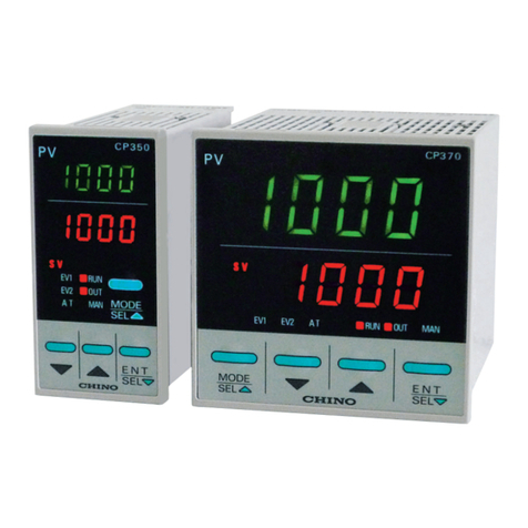
Chino JW Series User manual

CHINO
INST.No.INE-821
Three-Phase Thyristor Regulator
Communication Interfaces
Instruction Manual
JW Series


-CONTENTS -
INTRODUCTION..............................................................1
□
1OUTLINE ...................................................................2
1.1 RS-422A/485 Communication Interfaces................................................................................... 2
1.2 Communication Protocol ............................................................................................................. 2
1.3 Communication Specifications .................................................................................................... 2
□
2COMMUNICATION PARAMETER SETTING...........3
2.1 Communication Protocol (PtCL) Setting..................................................................................... 4
2.2 Address (AdrS) Setting ................................................................................................................ 4
2.3 Transmission Rate (rAtE) Setting................................................................................................ 4
2.4 Character (CHAr) Setting............................................................................................................. 4
□
3CONNECTIONS ........................................................5
3.1 Connection Precautions............................................................................................................... 5
3.2 Communication Cables ............................................................................................................... 6
3.3 Connection of RS-422A/485........................................................................................................ 9
□
4MODBUS PROTOCOL ...........................................10
4.1 Message Transmission Modes ..................................................................................................11
4.2 Data Time Interval ...................................................................................................................... 12
4.3 Message Configuration.............................................................................................................. 12
4.4 Message Creation Method ........................................................................................................ 19
4.5 Function Codes .......................................................................................................................... 21
4.6 Error Processing......................................................................................................................... 25
4.7 Reference Tables ....................................................................................................................... 27

-1-
INTRODUCTION
Note for Dealers and Instrument Suppliers Note for Users
Be sure to deliver this manual to the final user. Retain this manual carefully until the instrument is
disposed of.
This instruction manual describes exclusively the handling precautions and specifications of the
communication interfaces (RS-422A/RS-485) of the setting communication unit for the JW Series.
Reference manuals
This instruction manual describes the “Communication Interfaces ” instructions only on the JW Series. For the
descriptions on the thyristor regulators and the setting communication unit, refer to the separate manuals.
1) JW General (Instruction manual: INST. No. INE-819□)
2) JW Setting Communication Unit (Instruction manual: INST. No. INE-820□)
* In addition, refer to the instruction manual of the computer being used.
(1) The information given in this manual may be subject to change without notice.
(2) Every possible care was taken in compiling this manual. However, if you find a question,
error or mistake in it, please contact your dealer or local CHINO agent.
(3) In spite of (2) above, CHINO does not assume any liabilities concerning the results of the
instrument’s operation.
CAUTION
Thank you for purchasing the JW Series of thyristor regulator.
♦To use the instrument correctly and safely and to prevent troubles, read the manual carefully.

-2-
□
1OUTLINE
When these communication interfaces are added to the JW series communication setting unit, the setting of
parameters including the manual output, slope and elevation and information including the load voltage value,
current value, power value, resistance value and alarm can be collected from a master unit (PC, PLC, etc.). Two
communications interfaces, RS-422A and RS-485 are provided and can be selected by terminal connections.
The communication protocol employs MODBUS for easy configuration of a system with other instruments using
the same protocol.
1.1 RS-422A/485 Communication Interfaces
The RS-422A/485 communication interfaces allow multiple (up to 31) setting communication units and other
units to be connected to a same communication line.
When a PC is used as the master unit, it may sometimes be required to use an RS-232C ⇔RS-422A/485
signal converter. For this purpose, CHINO has a line converter (Model SC8-10) for RS-232C ⇔
RS-422A/485 signal conversion.
In the communication interfaces, the difference between RS-422A and RS-485 is that the RS-422A uses a
total of 4 lines composed of 2 lines for sending and 2 lines for receiving, and the RS-485 uses 2 signal lines
and switches sending and receiving.
1.2 Communication Protocol
The communication protocol is the MODBUS protocol. (MODBUS is a registered trademark of Schneider
Electric SA.)
The MODBUS protocol has the RTU and ASCII modes, which can be selected with the front function keys.
1.3 Communication Specifications
Communication type : Half-duplex asynchronous type
Communication protocol : MODBUS (RTU/ASCII)
Transmission rate : 9200 bps, 9600 bps
Start bit : 1-bit
Data length : 7-bit (ASCII mode)
: 8-bit (RTU mode/ASCII mode)
Parity bit : None/Even/Odd
Stop bit : 1-bit/2-bit
Communication code : ASCII (ASCII mode)
: Binary (RTU mode)
Error check : LRC (ASCII mode)
: CRC-16 (RTU mode)
: Parity
-3-
□
2COMMUNICATION PARAMETER SETTING
Set the four communication parameters of the communication protocol, address, transmission rate and
character following the flowchart shown below.
Mode0
Communication
Mode3
Character
Transmission
Rate
Address
Communication
Protocol
Press in any screen to return to Mode 3.
Key lock
3 times
ENT
MODE
Measured value display mode
* Set to “Lock” for performing various
settings via a master unit.
ENT ENT ENT
ENT
MODE

-4-
2.1 Communication Protocol (PtCL) Setting
(1)Pressthe keytoshow inDISP2.
(2) Press the or key to select the protocol, and then press the key to enter it.
Option Protocol Default
MODBUS RTU
MODBUS ASCII
* Changing the communication protocol initializes the character to the default setting.
2.2 Address (AdrS) Setting
For 1 set or multiple sets of the setting communication unit to be communicated with a master unit (PC, PLC,
etc.), an address not overlapping with the addresses of other setting communication unit should be set.
(1)Pressthe keytoshow inDISP2.
(2) Press the or key to select the address (01 ~ 99), and then press the key to enter it.
2.3 Transmission Rate (rAtE) Setting
The setting communication unit and a master unit (PC, PLC, etc.) should be run with the same transmission
rate.
(1)Pressthe keytoshow inDISP2.
(2) Press the or key to select the transmission rate, and then press the key to enter it.
Transmission rate: 9600 (9.6 k) or 19200 (19.2 k) bps (Default: 9600 bps)
2.4 Character (CHAr) Setting
(1)Pressthe keytoshow inDISP2.
(2) Press the or key to select the character, and then press the key to enter it.
Option Bit length Parity Stop bit Default
1
Even
2
1
7-bit
Odd
2
1
None
2
1
Even
2
1
8-bit
Odd
2
Each address should be between 01 and 99 and be set so that it does not overlap with addresses of
other setting communication unit or other units on the same communication line. (Default: 01)
CAUTION
ENT
ENT
ENT
ENT
ENT
ENT
ENT
ENT

-5-
□
3CONNECTIONS
3.1 Connection Precautions
3.1.1 Communication terminals
The terminal connection varies depending on the communication interface to be used.
No. RS-422A RS-485
(1) SDA SA
(2) SDB SB
(3) RDA Short with (1)
(4) RDB Short with (2)
(5) SG SG
(6) (No Connection)
3.1.2 The total length of the RS-422A/485 communication cable should be 1.2 km or less.
The intervals between units are not determined, but the total cable length should be 1.2 km or less.
Example (Distance between the line converter setting communication unit at the termination end)
3.1.3 Noise countermeasures
To avoid noise interference, separate the communication cable from drive power lines or other lines more
than 50cm.
3.1.4 Termination resistor
When using the RS-422A/485 communication, attach a 100-Ωresistor to the setting communication unit or
another unit placed at the termination end. (See Section 3.3 for details.)
(An ordinary metal film resistor can be used. It is also available from CHINO.)
3.1.5 Number of Setting Communication Units
Max. 31 units
Line converter
Total cable length < 1.2 ㎞
Set. Com. Unit
* The illustration shows an
example of the setting
communication unit’s
model number is 3. The
connection of the model
number 4 is performed on
the rear of the setting
communication unit.

-6-
3.2 Communication Cables
The exclusive communication cables should be prepared before proceeding to make a connection. These
cables are also available from CHINO.
3.2.1 RS-422A communication cable
(1) Connection between line converter and setting communication unit
Cable O-shaped crimp terminal Twisted wire RS-422A cable (for line converter)
Design
The cable is the 4-core cable twisted with the dual-core cables that are twisted with the
VCTF wires and has the SG (Signal Ground) wires at both ends. The SG wire on the
line converter side should be cut off because the line converter does not have an SG
terminal. The O-shaped terminals on the setting communication unit side should be cut
and stripped to expose the conductors.
Internal wiring
Model code
RZ-CRA2□□
Cable length: 01-99 m (To be specified)
(2) Connection between setting communication units
Cable Twisted wire Twisted wire RS-422A cable (For parallel connection)
Design
The cable is the 4-core cable twisted with the dual-core cables that are twisted with the
VCTF wires and has the SG (Signal Ground) wires at both ends,
Internal wiring
Model code
RZ-CRA1□□
Cable length: 01-99 m (To be specified)
Line converter side Set. Com. Unit side
O Cut tips and expose conductors.
RDA(Black)
RDB(White)
SDA(Red)
SDB(Green)
SG
(
Blue
)
(Black)SDA
(White)SDB
(Red)RDA
(Green)RDB
(
Blue
)
SG
RDA
RDB
SDA
SDB
SG
SDA
SDB
RDA
RDB
SG
Set. Com. Unit side Set. Com. Unit side
O Cut tips and expose conductors.
SDA (Black)
SDB (White)
RDA (Red)
RDB (Green)
SG
(
Blue
)
(Black)SDA
(White)SDB
(Red)RDA
(Green)RDB
(
Blue
)
SG
SDA
SDB
RDA
RDB
SG
SDA
SDB
RDA
RDB
SG

-7-
3.2.2 RS-485 communication cable
(1) Connection between line converter and setting communication unit
Cable O-shaped crimp terminal Twisted wire RS-485 cable (for line converter)
Design
The cable is the dual-core cable twisted with the CVVS wires and has the SG (Signal
Ground) wires at both ends. The SG wire on the line converter side should be cut off
because the line converter does not have an SG terminal.
Internal wiring
Model code
RZ-LEC□□□
Cable length: 001-200 m (to be specified)
(2) Connection between setting communication units
Cable Twisted wire Twisted wire RS-485 cable (For parallel connection)
Design
The cable is the dual-core cable twisted with the CVVS wires and has the SG (Signal
Ground) wires at both ends.
Internal wiring
Model code
RZ-CSS1Z2 (0.2 m) or RZ-LEC□□□
Cable length: 001-200 m (to be specified)
Line converter side Set. Com. Unit side
O Cut ti
p
s and ex
p
ose conductors.
RDA(Black)
RDB(White)
SG (Green)
(Black)SA
(White)SB
(Green)SG
RD
A
RDB
SG
SA
SB
SG
Set. Com. Unit side Set. Com. Unit side
O Cut tips and expose conductors
SA(Black)
SB(White)
SG (Green)
(Black)SA
(White)SB
(Green)SG
SA
SB
SG
SA
SB
SG

-8-
3.2.3 RS-232C communication cable (Reference)
(1) Connection between PC (9-pin) and line converter
Cable 9-pin connector O-shaped crimp terminal RS-232C cable
Design
Internal wiring
Model code
RZ-CRS6□□
Cable length: 1-15 m (Specification)
(2) Connection between PC (25-pin) and line converter
Cable 25-pin connector O-shaped crimp terminal RS-232C cable
Design
Internal wiring
Model code
RZ-CRS2□□
Cable length: 1-15 m (to be specified)
RS-232C cable (Max. length 15 m)
9-pin connector
on PC side
Line converter side
RD
SD
SG
1
2
3
4
5
6
7
8
9
RD
SD
SG
25-pin connector
on PC side
Line converter side
RS-232C cable (Max. length 15 m)
RD
SD
SG
For NEC PC 98 series
1
2
3
4
5
6
7
8
9
10
11
12
13
14
15
16
17
18
19
20
21
22
23
24
25
RD
SD
SG

-9-
3.3 Connection of RS-422A/485
The following example is the connection of the RS-422A/485 communication interface and a PC using the
line converter (model SC8-10). Since the connection between the line converter and the PC uses only 3
signal lines for the sending, the receiving and the signal ground and does not use other control signals, a
wiring arrangement inside the connectors is required like the connection of the RS-232C (For its details, refer
to the instruction manual for the line converter).
* If a line converter is at the termination end, a 100-Ωtermination resistor is also required across (5) – (6).
For Model SC8-10, shorting (4) –( 5) provides the termination resistor.
RS-422A connection
9-pin connector for a PC
6 7 8 9
1 2 3 4 5
RDA
RDB
SDA
SDB
Set. Com. Unit Set. Com. Unit Set. Com. Unit
Termination
resistor
100
Ω
Line converter
Do not connect the SG wire to
the FG or the ground terminal of
instruments.
CAUTION
SDA
SDB
RDA
RDB
SG
1
2
3
4
5
1
2
3
4
5
1
2
3
4
5
SDA
SDB
RDA
RDB
SG
SDA
SDB
RDA
RDB
SG
RD
SD
SG
1
2
3
4
5
6
7
8
1
2
3
4
5
* If a line converter is at the terminal end, a 100-Ωtermination resistor is also required across (5) – (6).
For Model SC8-10, shorting (4) – (5) provides the termination resistor.
RS-485 connection
9-pin connector for a PC
Termination
resistor
100
Ω
6 7 8 9
1 2 3 4 5
Line converter Do not connect the SG wire to
the FG or the ground terminal
of instruments
CAUTION
Set. Com. Unit Set. Com. Unit Set. Com. Unit
1
2
3
4
5
6
7
8
RDA
RDB
SDA
SDB
RD
SD
SG
1
2
3
4
5
1
2
3
4
5
1
2
3
4
5
SDA
SDB
RDA
RDB
SG
SDA
SDB
RDA
RDB
SG
SDA
SDB
RDA
RDB
SG

-10-
□
4MODBUS PROTOCOL
Basic Communication Procedure and Precautions
CAUTION
1. Set the Key Lock before setting (writing) a parameter.
The setting communication unit is ready for communication and can output the response to a data
request from a master unit (PC, PLC, etc.). However, for the setting of parameters from the master unit,
the setting communication unit should be set to the key lock status in advance. The key lock setting is
possible using the front keys of the setting communication unit or with communication from the master
unit. If the parameters are set to the setting communication unit under unlock status from the master
unit, the setting communication unit returns the error code 12H.
2. Care is required in command re-transmission due to no control signal lines used.
The serial interface of the setting communication unit performs communication without using
the control lines. As a result, care is required in retransmitting a command because receiving
failure may happen depending on the status of the setting communication unit. In addition,
when sending commands continuously, leave sufficient wait intervals between commands (1
second or more is recommended).
3. Do not disconnect cables/units or switch power ON/OFF during communication.
If cables or units in the serial interface are disconnected or power is switched OFF/ON during
communication, the operation may stop or an error may occur. If this happens, it is required to reset all
of the units in the serial interface and restart communication from the beginning.
4. Do not send a command before the communication drive is switched OFF.
With RS-485, multiple units are connected to a single communication line and only one having the
address specified by a master (PC, PLC, etc.) drives the communication line. To ensure arrival of all of
the characters at the master unit, the communication line drive is turned OFF in a certain period after
the last character is sent. If the PC sends a command to the next unit before the drive is turned OFF,
collision of signals makes normal communication impossible. This caution applies particularly when
using a high-speed PC. The period until the communication drive is turned OFF is about 5 ms.
5. The thyristor regulator may sometimes be reset when a control switching
command is issued.
When the setting communication unit is given the priority and the control being run is changed by
setting (writing) a control system (Ref. No. 1013) or feedback control (Ref. No. 41013), the thyristor
regulator performs the reset operation. Before sending a command to follow a control command,
reserve a sufficient wait time (3 sec. or more).
6.The settings are restricted according to the models.
Some settings are not available depending on the models of thyristor regulators. This caution applies
when using a model with the following control systems.
(1) Control system N: The feedback control setting is fixed at OFF.
(2) Control system Z: The feedback control setting is fixed at OFF (0).
The control system setting is fixed at zero-cross control (1).

-11-
4.1 Message Transmission Modes
The RTU (Remote Terminal Unit) or ASCII mode can be selected according to the front key setting.
(Table 1. Comparison between RTU and ASCII modes)
Items RTU mode ASCII mode
Interfaces RS-422A, RS-485
Communication type Half duplex asynchronous type
Transmission rate 9600, 19200 bps
Transmission code Binary ASCII
Vertical direction Parity
Error check Horizontal direction CRC-16 LRC
Start bit 1-bit
Data length 8-bit 7-bit/8-bit
Parity bit None/Even/Odd None/Even/Odd
Character
configuration
Stop bit 1-bit/2-bit
Start code of message None : (Colon)
End code of message None CR, LF
Data time interval 28-bit time or less 1 sec. or less
4.1.1 Data transmission
The RTU mode is based on binary data transfer. The ASCII mode decomposes 8-bit binary data of the
RTU mode into the higher 4-bit data and lower 4-bit data and converts each data item into a character (0 to
9, A to F).
Example) RTU mode ASCII mode
67H 36H ( “6” )
89H 37H ( “7” )
ABH 38H ( “8” )
39H ( “9” )
41H ( “A” )
42H ( “B” )
The RTU mode can transfer data more efficiently because its message length is half the ASCII mode.
4.1.2 Message frame configuration
The RTU mode message frame is composed only of the message part.
The ASCII mode message frame is composed of the start character “: (colon, or 3AH)”, a message and
the end character “CR (Carriage Return, or 0DH) + LF (Line Feed, or 0AH).”
RTU mode ASCII mode
Message : Message CR LF
The ASCII mode facilitates troubleshooting because it uses the start character “:” of message.

-12-
4.2 Data Time Interval
RTU mode: 28-bit time or less (9600 bps: 2.9 ms. 19200 bps: 1.4 ms.)
ASCII mode: 1 second or less
When sending a message, the time interval between data in a single message should not exceed the above
time limits. If a longer time interval has elapsed, the receiving unit (setting communication unit) recognizes that
the data transmission from the sending unit is complete, and processes the subsequent message as an
abnormal message. This means that the RTU mode requires continuous sending of message characters but
that the ASCII mode can send characters at intervals of maximum 1 second and a master unit (PC, PLC, etc.)
with a 5elatively slow processing speed can be used in this mode.
4.3 Message Configuration
The MODBUS message has a configuration as shown below in both the RTU and ASCII modes.
Slave address
2 Function codes
Data
Error check
4.3.1 Slave address
This corresponds to the address of the setting communication unit (Ref. Section 2.2). The address should
be set in advance in the range between 1 and 99 with the front keys. The master unit usually
communicates with a single slave unit. The message from the master unit is received by all units being
connected. However, only the slave unit having the address matching the slave address specification
included with the command message responds to its message.
The address “0” is used in a message from the master unit to all slave units (broadcast message). The
slave units do not send any response to the master unit.
4.3.2 Function codes
The function codes indicate the functions to be executed by the slave units. The data is generally classified
as shown below. For the details, refer to the reference tables.
(Function code list)
Code Function Unit MODBUS original function
(Reference)
01 Read digital (ON/OFF) parameter 1-bit Read coil status
02 Read digital input data 1-bit Read input relay status
03 Read analog parameter 16-bit Read buffer register
04 Read analog input data 16-bit Read input register
05 Write digital parameter 1-bit Change single coil status
06 Write analog parameter 16-bit Write single buffer register
08 Send received data (for diagnostics) Loop-back test
15 Write multiple digital parameters Change multiple coil statuses
16 Write multiple analog parameters Write multiple buffer registers

-13-
4.3.3 Data part
The configuration of data varies depending on the function code. A request from the master unit is
composed of the code number of the data to be read or written (the relative number calculated from the
reference number described below) and the quantity of data, etc. A response from the slave unit is
composed of the data corresponding the request, etc.
Every MODBUS basic data consists of 16-bit integers, and whether there is a sign or not is defined per
each data. Therefore, the data is configured as integers with their decimal places assigned in other
addresses, or normalized with the high and low limits specified by the scale with fixed decimal places. The
setting communication unit adopts the method of assigning the decimal places in other addresses.
4.3.4 Reference number
Each data in the setting communication unit is given a “Reference Number,” which is required for sending
and receiving the data. Each data is classified into “Digital parameter,” “Digital input data,” “Analog input
data” and “Analog parameter.” The designation of data in a message is executed by a “Relative number”
corresponding to each reference number as shown below.
(Reference number list)
Data types Reference number Relative number
Digital parameter 1 to 10000 Reference number -1
Digital input data 10001 to 20000 Reference number -10001
Analog input data 30001 to 40000 Reference number - 30001
Analog parameter 40001 to 50000 Reference number - 40001
4.3.5 Error check
The method of checking errors in the transferred frames varies depending on the mode.
RTU mode: CRC-16
ASCII mode: LRC
4.3.5.1 CRC-16 calculation
With the CRC method, the sent information is divided by a generator polynomial and the remainder is
appended after the data. The generator polynomial used is as follows:
1 + X2+ X15 + X16
The calculation is performed from the slave address till the end of data in the following procedure.
1) Initialization (= FFFFH) of CRC-16 data (assuming it is X).
2) Exclusive logical sum (EX-OR) between data 1 and X. →X
3) Shifting of X by 1 bit toward the right →X
4) When a carry is produced, EX-OR and A001H are taken. (If not produced, go to the step 5). →X
5) Steps 3) and 4) are repeated until 8 times of shifting.
6) EX-OR between the next data and X. →X
7) Same as steps 3) to 5)
8) Repetition of the above steps until the last data
9) Creation of a message in the sequence from low to high orders of the calculated 16-bit data (X)

-14-
Example) When data is , the CRC-16 calculation result is 1241H,
so the error check data becomes .
Reference 1: CRC-16 calculation program (C-language)
/***** CRC-16 Calculation Program *****/
#include <stdio.h>
#include <conio.h>
void main(void)
{
/*** Internal variable declaration ***/
unsigned int iLoopCnt; /* Loop counter */
unsigned short usData; /* Input data */
unsigned short usCrcData; /* CRC-16 data */
unsigned short usErrChkData; /* Error check data */
int iDummy; /* Dummy variable */
/* (1) Initialization of CRC-16 data output result */
usCrcData = 0xffff;
printf(“Input hex data. ([q] to quit) >¥n");
while( scanf("%x",&usData) != 0 ){
/* (2)(6) EX-OR of CRC output result and input data */
usCrcData = usData ^ usCrcData;
/*** CRC calculation ***/
/* (5) Repeating until 8 times of bit shifting */
for( iLoopCnt = 0 ; iLoopCnt < 8 ; iLoopCnt++ ){
/* (4) Checking whether carry is produced or not */
if( usCrcData & 0x0001 ){
/* (4) If a carry is produced */
/* (3) Shifting of CRC output result by 1 bit to the right */
usCrcData = usCrcData >> 1;
/* (4) EX-OR with A001H */
usCrcData = usCrcData ^ 0xa001;
}else
/* (4) If a carry is not produced */
/* (3) Shifting of CRC output result by 1 bit to the right */
usCrcData = usCrcData >> 1;
}
} /* for */
} /* while */
printf( “CRC-16 data is %xH. ¥n", usCrcData );
/* Creation of error check data */
usErrChkData = ( usCrcData >> 8) | ( usCrcData << 8 );
printf( “The error check data is %xH”, usErrChkData );
iDummy = getch();
}
02H 07H
41H 12H

-15-
Reference 2: CRC-16 calculation program (Microsoft Visual Basic.NET)
'***** CRC-16 Calculation Function *****/
Function fncCalcCrc(ByVal sCharData As String) As String
'*** Variable declaration ***
DimintLoopCnt1AsInteger 'Loopcounter1
DimintLoopCnt2AsInteger 'Loopcounter2
DimintLoopCnt3AsInteger 'Loopcounter3
DimintSdChrCntAsInteger 'Bytecountinsendingcharacter
DimintCrc16DataAsInteger 'Maskdata
DimintCarryFlgAsInteger 'Carryflagbuffer
DimstrWorkBufAsString 'Workbuffer
Dimint2ByteImage(16)AsInteger 'Shiftingbuffer
DimstrCRCAsString 'CRCresult
'*** Initial value setting ***
'* Calculation of bytes in the sending character *
intSdChrCnt=Len(sCharData)/2 'Sentstring2
'* Initialization of CRC-16 data (FFFFH)
intCrc16Data = &HFFFF
'*** CRC-16 calculation (CRC generator polynomial ---> 1+X^2+X^15+X^16) ***
'* Repeating with the same number as the byte count of sending character *
For intLoopCnt1 = 1 To intSdChrCnt
'* EX-OR between sending character and X : Every 2 bytes *
intCrc16Data = intCrc16Data Xor Val("&H" + Mid(sCharData, 2 * intLoopCnt1 - 1, 2))
'*Performingof8timesofshifting*
ForintLoopCnt2=0To7
'* Shifting of X by 1 bit to the right *
ForintLoopCnt3=0To15 'Checkingeachbitin2-bytesizedata
If (intCrc16Data And (2 ^ intLoopCnt3)) = 0 Then ' Is the bit 0?
int2ByteImage(intLoopCnt3) = 0 ' Set YES:0
Else
int2ByteImage(intLoopCnt3)=1 ' SetNO:1
EndIf
NextintLoopCnt3
'Checkingpereverybit
intCarryFlg=int2ByteImage(0) 'Bufferingofcarryflag
ForintLoopCnt3=1To15 'Shiftingofbits1to15by1bittotheright
int2ByteImage(intLoopCnt3-1)=int2ByteImage(intLoopCnt3)
NextintLoopCnt3
int2ByteImage(15)=0 'Setting0atthe15thbit
intCrc16Data=0 'ClearingCRC-16datato0
ForintLoopCnt3=0To15 'Convertingof16-dataarrayofthebitimage
' intoInttype
intCrc16Data=intCrc16Data+((2^intLoopCnt3)*int2ByteImage(intLoopCnt3))
NextintLoopCnt3 '(ForLoop)
'*Carryproduced?*
IfintCarryFlg=1Then
intCrc16Data=intCrc16DataXor&HA001 'EX-ORwithA001H

-16-
EndIf
NextintLoopCnt2 '(ForLoop)
NextintLoopCnt1 '(ForLoop)
'***
Creation of a message in the sequence from low to high orders of the calculated 16-bit data (X)
'* Setting by adding 0 at the head of the 4-byte data *
strWorkBuf="0000" 'Conversionofprocessingresultsinto4
' characters (set ‘0’ in lacking positions)
Mid(strWorkBuf, 5 - Len(Hex(intCrc16Data))) = Hex(intCrc16Data)
strCRC = Mid(strWorkBuf, 3, 2) & Mid(strWorkBuf, 1, 2) ' Exchanging of low and high data
' (Example) 1241H-->'41H''12H'
'*** Returned value ***
ReturnstrCRC 'CRCcharacter
End Function
* Microsoft Visual Basic.NET is a registered trademark of Microsoft Corporation.

-17-
4.3.5.2 LRC calculation method
The calculation is performed from the slave address until the end of the data in accordance with the
following procedure.
1) Creation of message in the RTU mode
2) Addition from the start (slave address) to end of the data →X
3) Calculation of the complement (bit inversion) of X →X
4) Addition of 1 (X = X+1)
5) Appending of X as the LRC at the end of the message
6) Conversion of the entire data into ASCII characters
Example) When data is , LRC is F7H so
the binary message becomes and
theASCIImessagebecomes .
Reference 1: LRC calculation program (C-language)
/***** LRC Calculation Program *****/
#include <stdio.h>
#include <conio.h>
void main(void)
{
/*** Internal variable declaration ***/
unsigned short usData; /* Input data */
unsigned short usLrcData; /* LRC data */
int iDummy; /* Dummy variable */
/* Initialization of LRC data output result */
usLrcData = 0;
printf(“Input hex data. ([q] to quit) >¥n”);
while( scanf("%x",&usData) != 0 ){
/* (2) Addition from the start to end of data */
usLrcData += usData;
/* Disposal of the highest 1 byte */
usLrcData = usLrcData & 0xff;
} /* while */
/* (3) EX-OR with FFH */
usLrcData = usLrcData ^ 0xff;
/* (4) Addition of 1 */
usLrcData = usLrcData++;
/* Disposal of the highest 1 byte */
usLrcData = usLrcData & 0xff;
/* LR error check */
printf( “The LRC-16 data is %xH. ¥n", usLrcData );
iDummy = getch();
}
02H 07H
02H 07H F7H
30H 32H 30H 37H 46H 37H
Table of contents
Other Chino Controllers manuals

Chino
Chino KP1000 User manual

Chino
Chino DB600 Series User manual

Chino
Chino DB600 Series User manual

Chino
Chino LT300 Series User manual

Chino
Chino JU Series User manual

Chino
Chino GT120 Series User manual

Chino
Chino LT830 Series User manual

Chino
Chino KP 2000 Series User manual

Chino
Chino KP3000 User manual

Chino
Chino DB630E User manual