Nivis ER-550 Installation manual

Acuity Edge Router ER-550
Hardware User Guide
(ER-550 Rev. C)
Version 1.0
Created: Mar. 4, 2008

Proprietary & Confidential – NIVIS LLC
Page 1 - V1.0
Revision History
Date Revision Description Author
03.03.2008 1.0 Create Document – Initial Draft Dan Cornescu

Proprietary & Confidential – NIVIS LLC
Page 2 - V1.0
Table of Contents
1. Scope ......................................................................................................................... 3
2. Introduction ............................................................................................................... 3
3. Mechanical View........................................................................................................ 3
4. Block Diagram ........................................................................................................... 4
5. User Configuration & Connections.......................................................................... 7
6. Internal Connections............................................................................................... 10
7. Start-Up Procedure ................................................................................................. 13
8. RF and Compliance................................................................................................. 14
Appendix 1................................................................................................................... 15

Proprietary & Confidential – NIVIS LLC
Page 3 - V1.0
1. Scope
The present document describes the Acuity Edger Router ER-550 hardware features.
2. Introduction
•The Acuity Edge Router ER-550 is designed to fulfill communications and data
acquisition requirement and use multiple communication channels (GPRS/EDGE
WAN + 10/100Base-T Ethernet port) and gather data via the 2.4GHz mesh
network radio link.
•The board is configured as intelligent LAN to WAN gateway for mesh sensor
networks applications. Data is stored and forwarded based on firmware
application.
•Board is operated continuously powered and includes circuitry that allows control
of power for sections of the board.
•Hardware includes a powerful ARM9 (@200MHz) and utilize a USB hub structure
and internal USB to serial converters in order to achieve communication
channels functionality
•Hardware includes a second MSP430 microcontroller that fulfills watchdog and
wake-up and monitoring duties for different modes of operation available.
•Communication modules are installed on a pluggable communication board on
top of the main board
•There are few connection available to user and include antenna connections,
Ethernet port and AC power connection, all other connections are internal in the
enclosure and are not directly accessible form outside.
•Design is AC powered and support an operating voltage range of 100-240VAC
•Hardware support operation temperatures range: -40C...+85C with up to 95%
non condensing humidity
3. Mechanical View
•Mechanical outline was designed to fit requirements
•Dimensions are presented in Appendix 1
Proprietary & Confidential – NIVIS LLC
Page 4 - V1.0
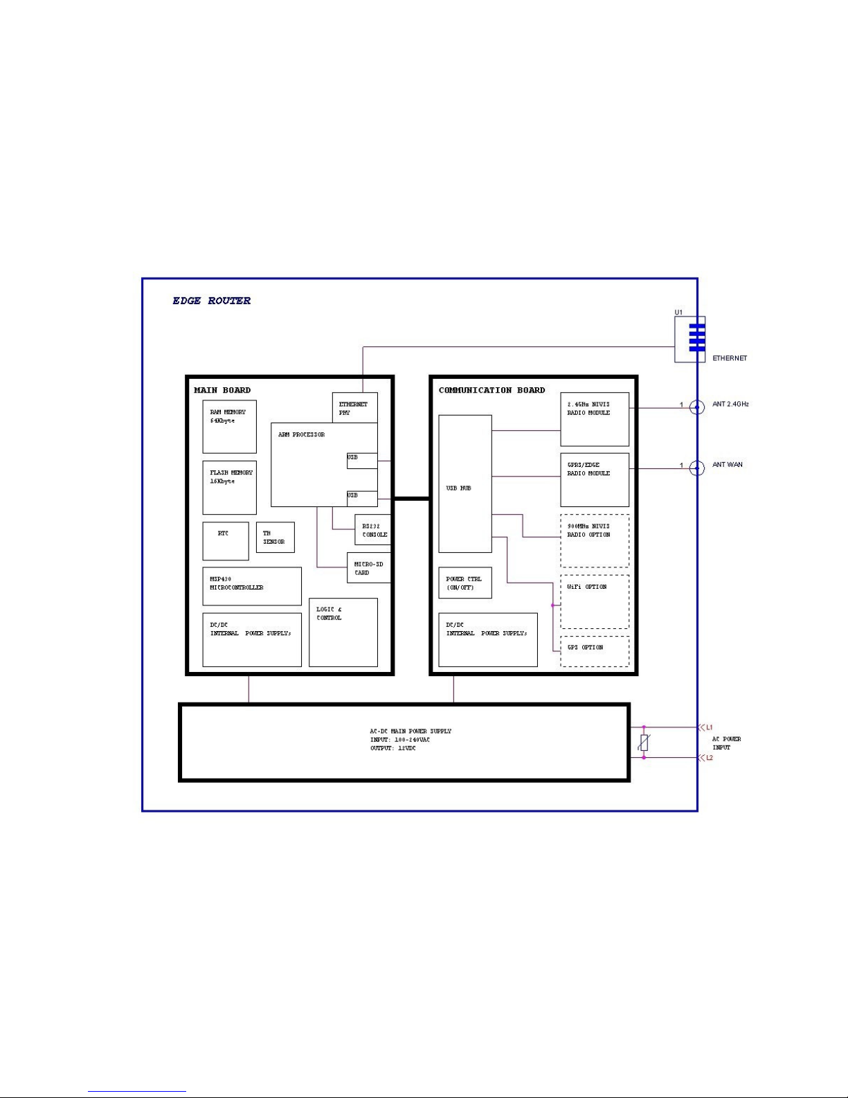
4. Block Diagram
Block diagram present the most important subsystems of the board.

Proprietary & Confidential – NIVIS LLC
Page 5 - V1.0
The Edge Router includes an ARM9 processor as the main processing entity that
controls most of the system features (some features are integrated internally into chip).
Subsystems controlled by the ARM processor are:
•Two directly connected serial channels. First channel is used for serial console
port used for factory programming and as debug console and is available on the
as RS232 connection. Second channel is used for intercommunication
(watchdog, commands, control and BSL mode) with the MSP430 microcontroller
that ensure system level watchdog and low power modes of operation. Also the
second channel is used for remote firmware upgrade of MSP430 code by using
the BSL mode programming mode.
•Two directly connected USB host channels. First channel is used for uplink USB
to a 4 port USB hub situated on the communication board in order to extend the
number of channels to necessary slot ports. Second channel is used for
providing the front panel USB user channel for administration via serial interface
and configuration purposes or as general USB host port for further applications.
•One Ethernet port (twisted pair port - 10/100Base-T). ARM processor implements
the Ethernet MAC internally and connects via the external PHY IC to RJ45
available connector on the main board.
•One 16-bit Data Address and Control bus for easy interfacing the memory
subsystem. Multiple chip select signals allow simple interface and multiple
methods for booting the system.
•Hardware SPI bus multiplexed for use with 2K Boot EEPROM option, micro-SD
card slot on main board for boot or storage or optional installed LCD panel.
•A large number of I/O grouped for internal control of board subsystems, for
control of power signals latch, for control of BSL programming mode of MSP430,
for implementing the I2C buses on the board. Two signals drive the Red and
Green on board LED’s.
The ARM memory subsystem is situated on the main board and includes the FLASH
memory (implemented 16Kbyte) and the two RAM memory chips (implement 2 x
32Kbyte). No buffering is included between memory and ARM processor. Boot of
system is realized from FLASH image programmed at factory. Also FLASH
accommodates the file system, application code and space for data storage. The RAM
memory is used to run the live system after boot, as temporary storage file system and
as memory allocated for system.
A set of 4 USB ports present on communication board are connected to USB-to-Serial
converters (internally) and supplemental circuitry that allow creation of slots
(communication slots) for the OEM installed communication modules. Slot powering is
controlled internally via a latch. This ensure a lot of flexibility for available power on/off
modes used in firmware.
The power supply subsystem include a 3.3V permanent power supply with low
quiescent current for MSP430 low power modes, a set of two power supply for 3.3V and
1.8V for the ARM, a 5V power supply for the USB hub and serial to USB converters and
level shifters of the communication board, one high current (up to 4A) switched power
supply for powering the OEM radio modules installed. Some extra linear regulators are

Proprietary & Confidential – NIVIS LLC
Page 6 - V1.0
present in order to efficiently provide the voltages for OEM modules and control the
power. Power supply can be switched ON/OFF under ARM control (separate for each
OEM module installed), the ARM power and USB hub power can be switched ON/OFF
under MSP430 control in order to support fine power management and a large
combination of modes of operation.
The main internal voltage is 12V and is provided by the AC-DC converter module
installed together with the main and communication board into the internal metallic
enclosure (for shielding purposes). Input voltage is AC trough installed power cord and
screw connections of the AC-DC power module.
Some auxiliary subsystems are present for internal management and include:
•Temperature and humidity sensor for environment management and alarms if
unit is exposed to values outside the specified range
•Precision hardware RTC used for applications that need precise time keeping,
also this is the 32KHz reference for the ARM processor internal RTC. The RTC
selected should allow drifts of no more than 3-4 seconds/month under normal
conditions and better if calibration trimmed at factory.
•Analog measurements via ARM analog input pins for on board voltages in order
to allow alarms when on board circuitry present anomaly in usage or onboard
components are faulty affecting the correct range for voltages.
Whole boards are installed stacked into the inside metallic enclosure and include the
power supply (in order to minimize the RF emissions). The external connections for
antennas and Ethernet are routed outside the metallic enclosure to proper connectors
on the IP-65 certified external plastic enclosure.
Proprietary & Confidential – NIVIS LLC
Page 7 - V1.0
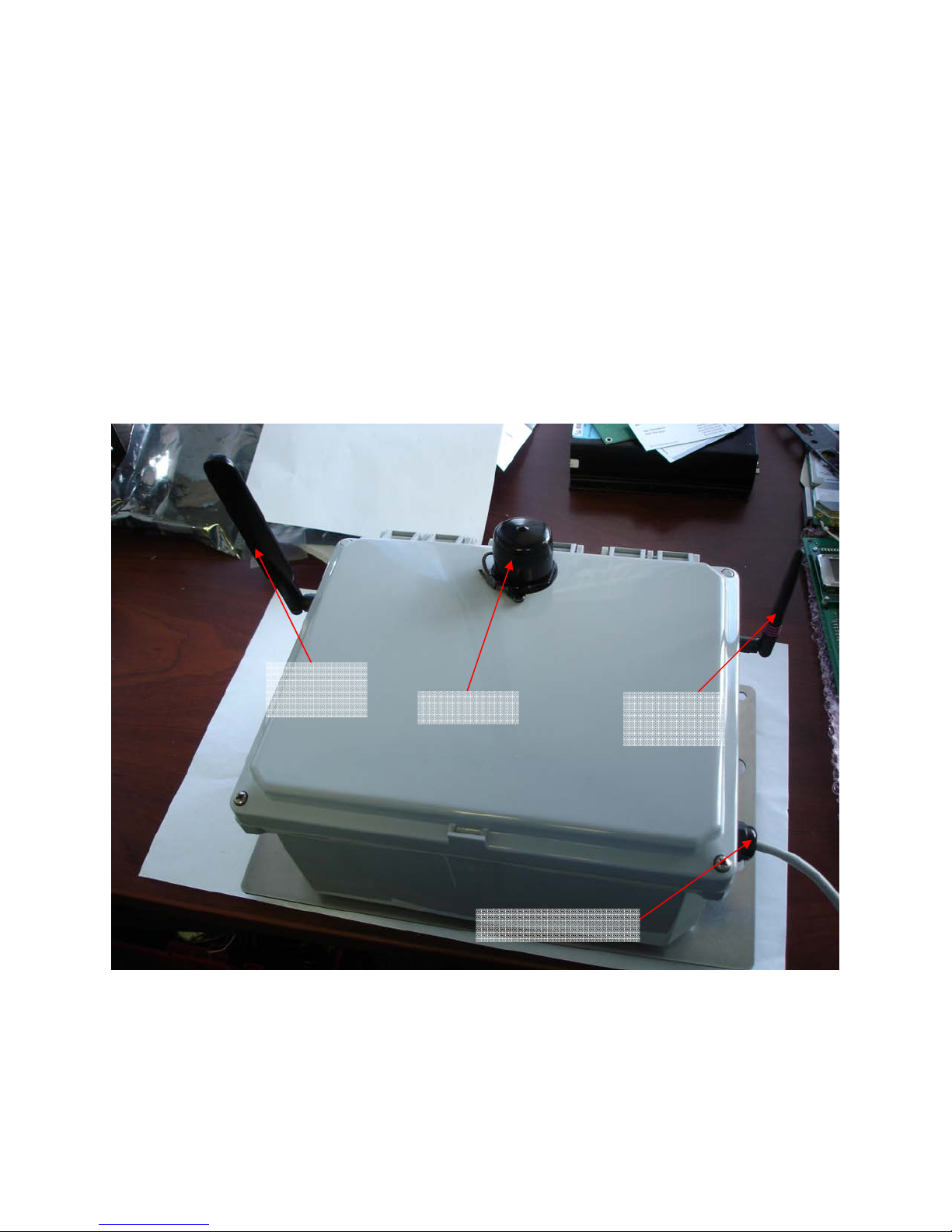
5. User Configuration & Connections
5.1 Power Connection
•Power is connected trough grummet situated on the right side of the unit
•Recommended connection via PVC or Teflon insulated power cable with minimal
AWG #24 conductor size.
•Please check installation manual for other available connection types
Ethernet
GPRS
Antenna 2.4GHz
Antenna
AC Power Input

Proprietary & Confidential – NIVIS LLC
Page 8 - V1.0
5.2 External Ethernet Port Connection (10/100Base-T, RJ45)
•Ethernet port connects externally trough an RJ-45 type water proof connection
on top of the enclosure
•Proper cabling need to be used according to specifications for network cabling.
(PC use cross cable, connection via Hub use straight cable, or as specified)
•Ethernet subsystem can be power down under firmware control using board
internal control I/O pins in order to avoid extra consumption (when not used)
•Pin usage for Ethernet (10/100Base-T, RJ45 connection) are presented below:
Pin
Signal
Description
Direction
1 TD+ Transmit Data (+) Line Output
2 TD- Transmit Data (-) Line Output
3 RD+ Receive Data (+) Line Input
4 Not Used
5 Not Used
6 RD- Receive Data (-) Line Input
7 Not Used
8 Not Used
•Usage of a Lightening Protection device between Ethernet port and actual
connection cable is recommended for exterior installations. We recommend
usage of a device similar to http://www.hyperlinktech.com/web/al-cat5w.php .
Pin1

Proprietary & Confidential – NIVIS LLC
Page 9 - V1.0
5.4 Antenna Ports
•Antenna ports are situated on the sides of the enclosure.
•Antennas used have been specified in accordance to FCC certifications for the
device.
•On the left side of enclosure (the pedal shaped antenna) is the WAN connection
antenna. This is a quad band antenna specifically designed for GSM/GPRS
operation.
GPRS/EDGE – WAN ANTENNA
Description ANTENNA RUBBR DUCK MULT-BAND SMA
Model T6140AM-AGDPU-S
Manufacturer Nearson Inc.
Vendor Digi-Key Corporation
Vendor P/N 730-1016-ND
Gain [dBi] 2.0
Connection Type SMA (Male), Swivel
•On the right side of enclosure (the ring marked) is the mesh LAN connection
antenna. This is a 2.4GHz antenna specifically designed for ISM band operation.
2.4GHz – MESH LAN ANTENNA
Description ANTENNA 2.4GHZ 1/2 WAVE RP/SMA
Model ANT-2.4-CW-RCT-RP
Manufacturer Antenna Factor
Vendor Digi-Key Corporation
Vendor P/N ANT-2.4-CW-RCT-RP-ND
Gain [dBi] 2.2
Connection Type SMA Reverse (Female), Swivel
GPRS/EDGE
Antenna
2.4GHz Mesh
LAN Antenna
Proprietary & Confidential – NIVIS LLC
Page 10 - V1.0
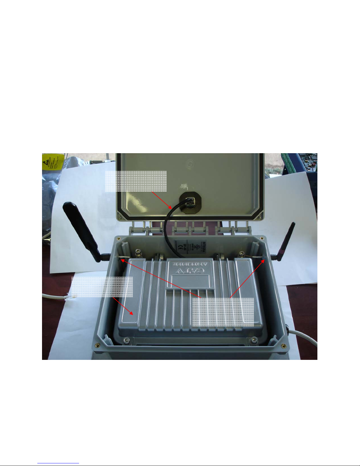
6. Internal Connections
6.1 Connectors and cables
•Internal Connections are used for engineering diagnostics and factory
configuration of the unit.
•Usage and access to those connection are described in separate documents
•Those connections are internal and accessible only if unit is opened
•WARNING: Unit can be damaged by improper use of internal connections
•Enclosure View
Internal Metallic
Enclosure
Internal Ethernet
Cable
Bulkhead
Antenna
Connections

Proprietary & Confidential – NIVIS LLC
Page 11 - V1.0
•Communication Board View
•Main Board View
GPRS/EDGE
Module
2.4GHz Module
SIM CARD
LED’s
AC-DC
Power Supply
AC Input
12V DC Input
Ethernet
RS232
Console
USB
ALARM S
Micro-SD
LCD
Expansion
ARM Processor
EXPANSION
CONN

Proprietary & Confidential – NIVIS LLC
Page 12 - V1.0
6.2 RTC Back-up Battery
•The device contain a coin cell battery socket to accommodate battery for RTC
•Socket should be populated with a coin cell CR2032 battery type
•Follow indicated polarity for battery installation, (+) on bottom.
•Anticipated battery life based on theoretical calculations is 10 years.
•Battery should be replaced as needed based on unit usage
•Inspection for corrosion is recommended when battery change is done
•WARNING: Unit can be damaged by polarity reverse battery installation
•Default Factory Configuration: CR2032 Lithium Battery Installed (10 year life)
RTC
CR2132 Coin
Cell Battery

Proprietary & Confidential – NIVIS LLC
Page 13 - V1.0
7. Start-Up Procedure
7.1 Quick Power-On
•System is factory preconfigured with firmware to support intended application
•First Install mechanically the Edge Router according to Installation Manual
•Verify proper installation and positioning of the external antennas.
•Install power connection and apply AC power to the system.
•Wait about 1-2 minutes for the system to boot and connect to NOC
•Verify with NOC specialists if system has registered and all subsystems are
running properly
•Coordinate tests and actions with NOC personnel if issues appear at installation
•There are no field accessible configuration elements on the hardware of the
device, configuration changes are solely achieved under firmware control
Note: The Ethernet port can be used for field configuration and debug according
to documentation provided. For direct PC or PDA connection use appropriate
crossed type cable.

Proprietary & Confidential – NIVIS LLC
Page 14 - V1.0
8. RF and Compliance
8.1 RF Exposure Limits WARNING
To comply with FCC’s RF exposure limits for general population / uncontrolled
exposure, the antenna(s) used for this transmitter must be installed to provide a
separation distance of at least 20cm from all persons and must not be collocated or
operating in conjunction with any other antenna or transmitter.
8.2 Compliance Statement (Part 15.19)
This Device complies with Part 15 of the FCC Rules.
Operation is subject to the following two conditions:
•This device may not cause harmful interference.
•This device must accept any interference received, including interference that
may cause undesired operation.
8.3 Information to the user (Part 15.105)
This equipment has been tested and found to comply with the limits for a Class B digital
device, pursuant to Part 15 of the FCC Rules. These limits are designed to provide
reasonable protection against harmful interference in a residential installation. This
equipment generates uses and can radiate radio frequency energy and, if not installed
and used in accordance with the instructions, may cause harmful interference to radio
communications. However, there is no guarantee that interference will not occur in a
particular installation. If this equipment does cause harmful interference to radio or
television reception, which can be determined by turning the equipment off and on, the
user is encouraged to try to correct the interference by one or more of the following
measures:
•Reorient or relocate the receiving antenna.
•Increase the separation between the equipment and receiver.
•Connect the equipment into an outlet on a circuit different from that to which the
receiver is connected.
•Consult the dealer or an experienced radio/TV technician for help.
8.4 WARNING (Part 15.21)
Changes or modifications not expressly approved by the party responsible for
compliance could void the user’s authority to operate the equipment.

Proprietary & Confidential – NIVIS LLC
Page 15 - V1.0
Appendix 1
•Mechanical outline and dimensions:
Table of contents
Other Nivis Network Router manuals

Popular Network Router manuals by other brands

Vista
Vista QSW8 user manual

DataRemote
DataRemote CDS-9010 quick start guide

Vimar
Vimar Well-contact Plus manual

TP-Link
TP-Link SafeStream TL-ER5120 installation guide

DIGITAL FORECAST
DIGITAL FORECAST Bridge RS16x16 instruction manual

Cyclades
Cyclades Access Router Cyclades-PR2000 Quick installation manual


