Nivus EnerPro User manual
550602_EnerPro24V-Tr_v04 / Rev. 04 / 15.01.2018
NIVUS GmbH
Im Täle 2
D-75031 Eppingen
Telefon: +49 (0)7262 9191 - 0
Fax: +49 (0)7262 9191 - 999
E-mail: info@nivus.com
Web: www.nivus.com
Technische Änderungen sowie Liefermöglichkeiten
vorbehalten.
Specifications and delivery options subject to change.
Sous réserve de modifications techniques et de possibilités
de livraison.
Betriebsanleitung
EnerPro 24V-Tr
Überspannungsableiter
Typ BSL0EP1-2400
Operating instructions
EnerPro 24V-Tr
Surge protective device
Typ BSL0EP1-2400
Instructions d’emploi
EnerPro 24V-Tr
Parasurtenseur
Type BSL0EP1-2400
Beschreibung
Bei diesem Überspannungsableiter handelt
es sich um eine zweistufige
Schutzschaltung, deren Grobschutz-
elemente gasgefüllte Überspannungs-
ableiter sind. Der Feinschutz besteht aus
einer Suppressordiode. Da auf den Einsatz
von Varistoren ganz verzichtet wurde,
treten keine nennenswerten Leckströme
auf.
Description
This device consists of a two-stage
protective circuit with gas-filled surge
protectors as basic protection elements.
Ultimate protection consists of a suppressor
diode. As no varistors have been used no
leakage currents of any significance arise.
Description
Dans le cas de ce parasurtenseur, il s’agit
d’un circuit de protection à deux niveaux
dont les éléments destinés à la protection
de base sont des parasurtenseurs à gaz
rare. La protection de précision se compose
d’une diode de suppression. Aucun courant
de fuite notable n’apparaît puisqu’il a été
fait abstraction de varistances.
Installations- und Betriebshinweise
Dieser Ableiter wird zum Schutz von
Stromversorgungsleitungen eingesetzt.
VORSICHT
Das Schutzgerät muss möglichst nah am zu
schützenden Gerät angeschlossen werden.
Geschützte und ungeschützte Leitungen
dürfen nicht zusammen verlegt werden.
Installation / Operating instructions
This surge protector is used for the
protection of power supply lines.
ATTENTION
The protective device must be connected as
closely as possible to the equipment to be
protected.
Protected and unprotected lines must not
be laid together.
Directives d’installation et d’exploitation
Ce parasurtenseur est utilisé pour la
protection des lignes d´alimentation.
ATTENTION
L’appareil de protection doit si possible
être raccordé près de l’appareil à protéger.
Les lignes protégées et les lignes non
protégées ne doivent pas être posées
ensemble.
1
(3)
2
3
4
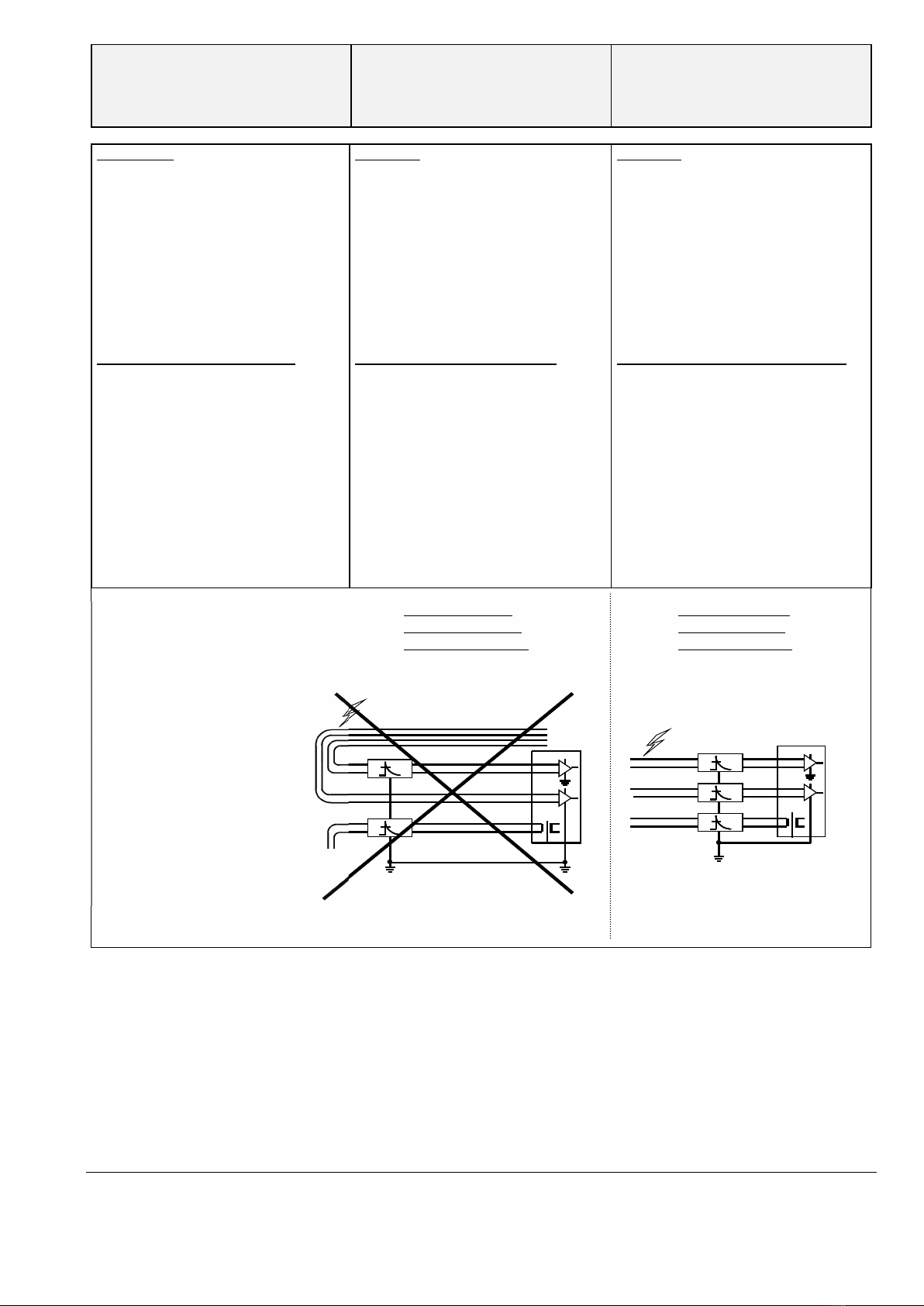
Falsche Installation Richtige Installation
Installation incorrect Installation correct
Installation incorrecte Installation correcte
Legende / legend / légende
1. Falsche Leitungsführung
Cable layout incorrect
Introduction des câbles incorrecte
2. Ungeschützter Eingang
Unprotected input
Entrée non protégée
3. Zu lange Leitungen
Cables too long
Câbles trop longs
4. Zwei Erdungen
Two grounds
Deux mise à la terre

550602_EnerPro24V-Tr_v04 / Rev. 04 / 15.01.2018
NIVUS GmbH
Im Täle 2
D-75031 Eppingen
Telefon: +49 (0)7262 9191 - 0
Fax: +49 (0)7262 9191 - 999
E-mail: info@nivus.com
Web: www.nivus.com
Technische Änderungen sowie Liefermöglichkeiten
vorbehalten.
Specifications and delivery options subject to change.
Sous réserve de modifications techniques et de possibilités
de livraison.
Betriebsanleitung
EnerPro 24V-Tr
Überspannungsableiter
Typ BSL0EP1-2400
Operating instructions
EnerPro 24V-Tr
Surge protective device
Type BSL0EP1-2400
Instructions d’emploi
EnerPro 24V-Tr
Parasurtenseur
Type BSL0EP1-2400
Wartung
Es ist empfehlenswert, die Funktion dieses
Ableiters nach jeder Blitzsaison oder
häufiger zu überprüfen. Ansonsten ist
dieses Produkt wartungsfrei.
Maintenance
Merely check this surge protector for
correct operation after the period when
thunderstorms are most frequent. Apart
from that this product requires no
maintenance.
Maintenance
Il est recommandé de contrôler le
fonctionnement de ce parasurtenseur après
chaque période d’activité orageuse intense.
A part cela, ce produit est exempt de
maintenance.
Fehlererkennung
Bei Bedarf kann dieser Ableiter durch eine
Isolations- und Durchgangsmessung
überprüft werden. Bei Risol < 1 MΩ(1 gegen
2 und PE bzw. 2 gegen PE) oder bei
Unterbruch (1 zu 1p und 2 zu 2p) muss der
Ableiter ausgewechselt werden (siehe
Schema).
Trouble-shooting
As and when required, this surge protective
device can be checked by measuring
insulation and continuity. With an
insulation resistance of < 1 MΩ, measure (1
to 2 and PE or 2 to PE), or with open line (1
to 1p and 2 to 2p) the surge protective
device must be replaced (see diagram).
Reconnaissance de défauts
Au besoin, ce parafoudre peut être vérifié
par une mesure d’isolation et une mesure de
passage. Pour une résistance d’isolement
< 1 MΩ(1 contre 2 et PE, resp. 2 contre PE)
ou, pour rupture (1 à 1p et 2 à 2p), le
parafoudre doit être remplacé (voir
schéma).
VORSICHT
Der PE-Anschluss muss immer
angeschlossen werden.
ATTENTION
The PE terminal must always be connected.
ATTENTION
La connexion PE doit toujours être
raccordée.
EU Konformitätserklärung
EU Declaration of Conformity
Déclaration de conformité UE
EU Richtlinie: EN 2014/30/EU
EN 2014/35/EU
EN 2011/65/EU (RoHS)
Normen: EN 61643 – 11:2013
EN 61643 – 21:2013
EC directives: EN 2014/30/EU
EN 2014/35/EU
EN 2011/65/EU (RoHS)
Standards: EN 61643 – 11:2013
EN 61643 – 21:2013
UE directive: EN 2014/30/EU
EN 2014/35/EU
EN 2011/65/EU (RoHS)
Normes: EN 61643 – 11:2013
EN 61643 – 21:2013
IEC-Prüfklasse / EN-Type: Typ 2+3 / class
II+III
IEC-Test category / EN-Type:
Type 2+3 / class II+III
IEC-classe de contrôle / EN-Type:
Type 2+3 / class II+III
Technische Daten
Max. Betriebsspannung .............
Max. Betriebsstrom ...................
Schutzpegel 1-2/1, 2-PE.............
Nennableitstoßstrom.................
Anschlüsse .................................
Technical data
Max. operating voltage...............
Max. operating current...............
Protection level 1-2/1, 2-PE........
Nom. imp. disch. current ............
Connections................................
Données techniques
Tension max. de service .............
Courant max. de service.............
Niveau de protection 1-2/1, 2-PE
Intensité de pointe de déch. nom
Connexions.................................
DC / AC
...............
...........................
1.2/50 µs
............
20 kA (8/20 µs)
...
8/20 µs
...............
...........................
27 / 20 V
6 A
≤37 / 800 V
≤55 / 800 V
20 kA
2.5 mm2
Abmessungen / dimensions / dimensions [mm]
Schema / diagram / schéma
(p = geschützt, protected, protégé)
PE
1
2
1
2
p
p
F
+(−)
−(+)
This manual suits for next models
1
Other Nivus Surge Protector manuals


Popular Surge Protector manuals by other brands


Intermatic
Intermatic 177547 installation instructions

Monster Power
Monster Power HDP 1800 owner's manual

AccelTex
AccelTex ATS-SS-64V-10KA-10GBPS-BT installation guide

Transparent
Transparent POWERBANK 6 owner's manual

CablesPlus
CablesPlus GoldX PowerCore user guide

Bretford
Bretford 35PBCFPS Specifications