24 Karat Warranty
JDI warrants this PowerCore System to be free of defects in materials and
workmanship for the useful lifetime of the product.
24 Karat Connected Equipment Warranty
If, during the time period listed for your model (see chart), any equipment
properly connected to the PowerCore System is damaged by a transient
spike on the AC power line (as defined by industry standards) that enters
the equipment through a properly installed GoldX PowerCore System,
Jo-Dan International, Inc.(JDI) will reimburse your reasonable cost to repair
or replace the damaged equipment (at the option of JDI) up to a maximum
U.S. dollar amount (see chart), subject to the following conditions: 1. Proper
Installation: The GoldX PowerCore System must be plugged directly into a
properly wired and grounded AC outlet; no extension cords, adapters, other
ground wires or electrical connections may be used to connect the GoldX
PowerCore System to AC power. The wiring in the building must comply with
all applicable codes (e.g., NEC or CSA). 2. Proper Equipment Connection:
All wires leading into the equipment must pass through an appropriate
GoldX PowerCore System. To claim damage as a result of telephone line
transients, the equipment must be properly connected to a GoldX PowerCore
System which offers telephone line protection, and your telephone service
equipment must include a properly installed and operating “primary
protection” device at the service entrance. (Such devices are normally
added during telephone line installation.)
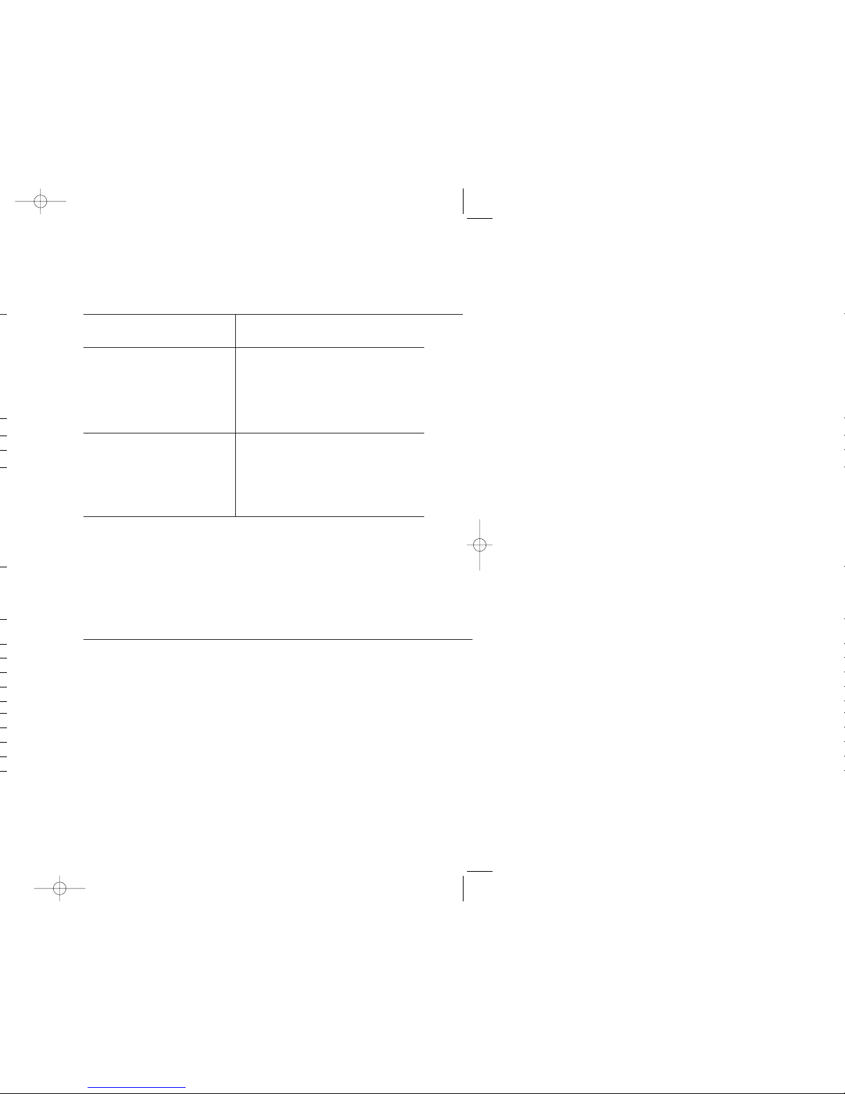
Product Warranty
Lifetime
Equipment Warranty
$25,000
Equipment Warranty
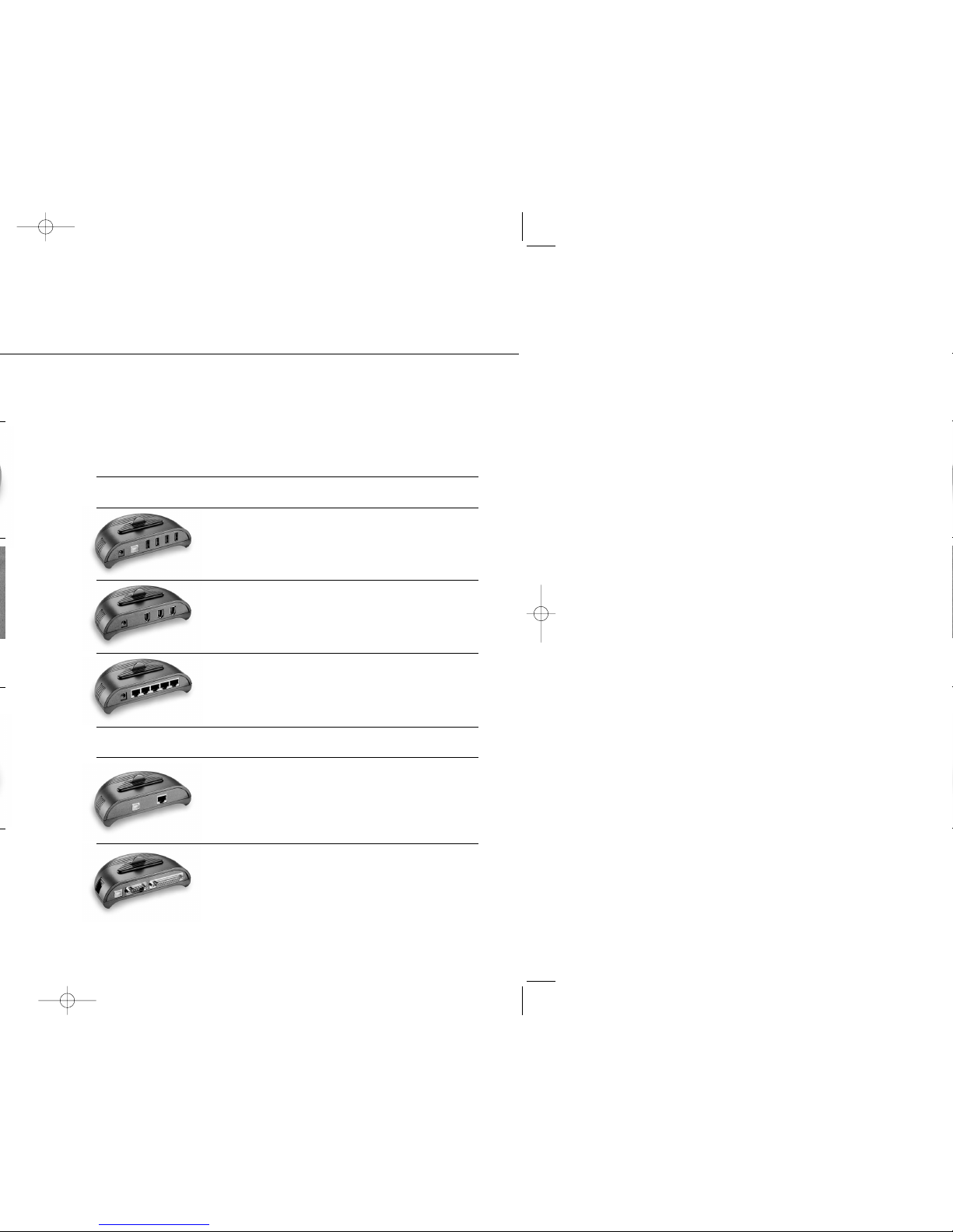
Power-Line Spikes,
Power-Line Surges,
Coaxial Spikes,
Ethernet Spikes,
Phone-Line Spikes
GXSB-7555
USERS GUIDE
1716
What These Warranties Do Not Cover.
THIS WARRANTY DOES NOT COVER PRODUCT THAT HAS BEEN MISUSED, IMPROPERLY INSTALLED,
TAMPERED WITH OR ALTERED IN ANY WAY, OR IF THECONNECTED EQUIPMENT WAS NOT USED UNDER
NORMAL OPERATION CONDITIONS IN ACCORDANCE WITH ANY LABELS OR INSTRUCTIONS. THESE
WARRANTIES DO NOT INCLUDE: DAMAGE RESULTING FROM ACCIDENT OR MISUSE; DAMAGE RESULT-
ING FROM A LIGHTNING STRIKE; AND TRANSIENT SPIKES ON DATA, COAXIAL OR COMMUNICATIONS
LINES ATTACHED TO THE CONNECTED EQUIPMENT EXCEPT AS PROVIDED ABOVE (SEE CHART).
THESE WARRANTIES SPECIFICALLY DO NOT COVER SUSTAINED OVERVOLTAGES (LONGER THAN 500
MICROSECONDS). EXCEPT AS PROVIDED ABOVE, IN NO EVENT WILL JDI BE LIABLE FOR DIRECT,
INDIRECT, SPECIAL, INCIDENTAL OR CONSEQUENTIAL DAMAGES ARISING OUT OF THE USE OF THIS
PRODUCT, EVEN IF ADVISED OF THE POSSIBILITY OF SUCH DAMAGE. SPECIFICALLY, JDI IS NOT LIABLE
FOR ANY COSTS, SUCH AS LOST PROFITS OR REVENUE, LOSS OF EQUIPMENT, LOSS OF USE OF
EQUIPMENT, LOSS OF SOFTWARE OR DATA, COST OF SUBSTITUTES, CLAIMS BY OTHER PARTIES,
OR OTHERWISE. THESE WARRANTIES DO NOT COVER ANY DAMAGE TO PROPERLY CONNECTED
EQUIPMENT RESULTING FROM A CAUSE OTHER THAN A TRANSIENT SPIKE. THE CONNECTED EQUIP-
MENT LIMITED WARRANTY IS NOT TRANSFERRABLE FROM THE ORIGINAL SYSTEM OF REGISTRATION
TO ANOTHER. SOME STATES DO NOT ALLOW THE EXCLUDING OR LIMITATION OF INCIDENTAL OR
CONSEQUENTIAL DAMAGES, SO THE ABOVE LIMITATION OR EXCLUSION MAY NOT APPLY TO YOU.
THESE WARRANTIES GIVE YOU SPECIFIC LEGAL RIGHTS, AND YOU MAY ALSO HAVE OTHER RIGHTS
WHICH VARY FROM STATE TO STATE. VALID IN U.S.A. AND CANADA ONLY.
Claims Procedure: In the event the properly connected equipment is damaged as a result of an AC
transient spike passing through a properly installed GoldX PowerCore System, the consumer must follow
these procedures: 1. Returning the PowerCore System: You should first call JDI to obtain a Return
Authorization Number then return the PowerCore System with transportation charges prepaid to JDI for
verification of surge damage accompanied by a brief description of how the damage occurred and proof
of data and place of purchase. Please print your Return Authorization Number on the outside of the
returned package where it can be easily seen or the package will be refused at JDI’s receiving dock and
returned to you. 2.Filling a Connected Equipment claim: At the time a Return Authorization Number
is issued, notification of damage to connected equipment must be given to JDI. To receive reimbursement
for damage to connected equipment due to a covered power disturbance, you must first have repairs
performed by a technician who is authorized by the manufacturer of the equipment and pay for those
repairs, or purchase new equipment, whichever is more economical. A copy of the bill and a report from
the Authorized Technician will determine whether the PowerCore System failed to provide protection. All
reports will be available to the claimant. Determination of Failure: The returned PowerCore System will be
tested by JDI to determine whether the product failed to provide protection. An evaluation of the results
of that test and of the report from the Authorized Technician will determine whether the PowerCore
System failed to provide protection.
NOTE: JDI reserves the right to inspect the damaged connected equipment, parts, or circuit boards, as
well as the customer’s facility (at JDI’ expense). Damaged parts must be available for inspection in their
unaltered state until the claim is finalized. Reimbursement. If all of the above requirements are met
and the GoldX PowerCore System failed to provide protection, JDI will reimburse the claimant for the
connected equipment at fair market value or for the repair of the connected equipment at customary
and reasonable rates (at JDI’s option) up to the maximum U.S. dollar amount listed for your model
(see chart). If the claimant is a dealer and replacement of connected equipment is selected, JDI will not
reimburse repair bills exceeding current replacement value of connected equipment. Whenever claims
are settled, JDI reserves the right to be subrogated under any insurance policies of the claimant.
Disclaimer: JDI’s policy is that all products meet their performance criteria. If the product performance
criteria specified has failed, however, we will replace the product for the life of the product.
Warranty Information