NKE Topline Series Manual
nke – Sailing competition
Z.I. Kerandré – Rue Gutenberg – 56700 HENNEBONT- FRANCE
http://www.nke.fr – N° indigo 0 892 680 656 : 0.34€/min.
Multifunction
SL50
and its remote control
Product reference : 90-60-445 white / 90-60-472 carbon
USER GUIDE
and
INSTALLATION GUIDE

- 2 – SL50 User guide – 33-60-022-000
TABLE OF CONTENT
1 USING ...................................................................................................................................3
1.1 PRESENTATION.....................................................................................................................3
1.2 LIST OF CHANNELS CREATED..................................................................................................5
1.3 KEYPAD FUNCTIONS OF THE REMOTE CONTROL........................................................................6
1.4 CHANNEL SELECTION ............................................................................................................7
1.5 WHAT IS A SUB-CHANNEL.......................................................................................................7
1.6 ALARMS SETTING ..................................................................................................................8
1.7 FILTERING OF THE CHANNELS.................................................................................................9
1.8 LIGHTING SETTING...............................................................................................................10
1.9 CHOICE OF THE UNIT ...........................................................................................................10
1.10 CALIBRATION OF SENSORS ...............................................................................................13
1.11 AUTOCOMPENSATION OF THE FLUXGATE COMPASS .............................................................14
1.12 ZERO SETTING OF THE DAILY LOG ......................................................................................11
1.13 CHOICE OF LANGUAGES ...................................................................................................10
1.14 USE OF THE CHRONOMETER .............................................................................................12
1.15 TECHNICAL SPECIFICATIONS .............................................................................................14
1.16 VERSION AND ADDRESS NUMBER OF THE DISPLAY...............................................................15
1.17 DIAGNOSTIC FOR 1ST LEVEL TROUBLESHOOTING. ................................................................15
1.18 SL50 INITIALISATION : SEE CHAPTER 4.8 ...........................................................................15
2 INSTALLATION...................................................................................................................16
2.1 PACKING LIST : ...................................................................................................................16
2.2 LIST OF ACCESSORIES .........................................................................................................16
2.3 INSTALLATION PRECAUTIONS................................................................................................16
2.4 MOUNTING ON MAST FOOT SUPPORT.....................................................................................17
2.5 WALL MOUNTING.................................................................................................................17
2.6 CONNECTION TO THE TOPLINE BUS.......................................................................................19
2.7 IDENTIFICATION OF THE CABLE WIRES ...................................................................................19
2.8 SL50 AND REMOTE CONTROL INITIALISATION .........................................................................20

- 3 – SL50 User guide – 33-60-022-000
1 USING
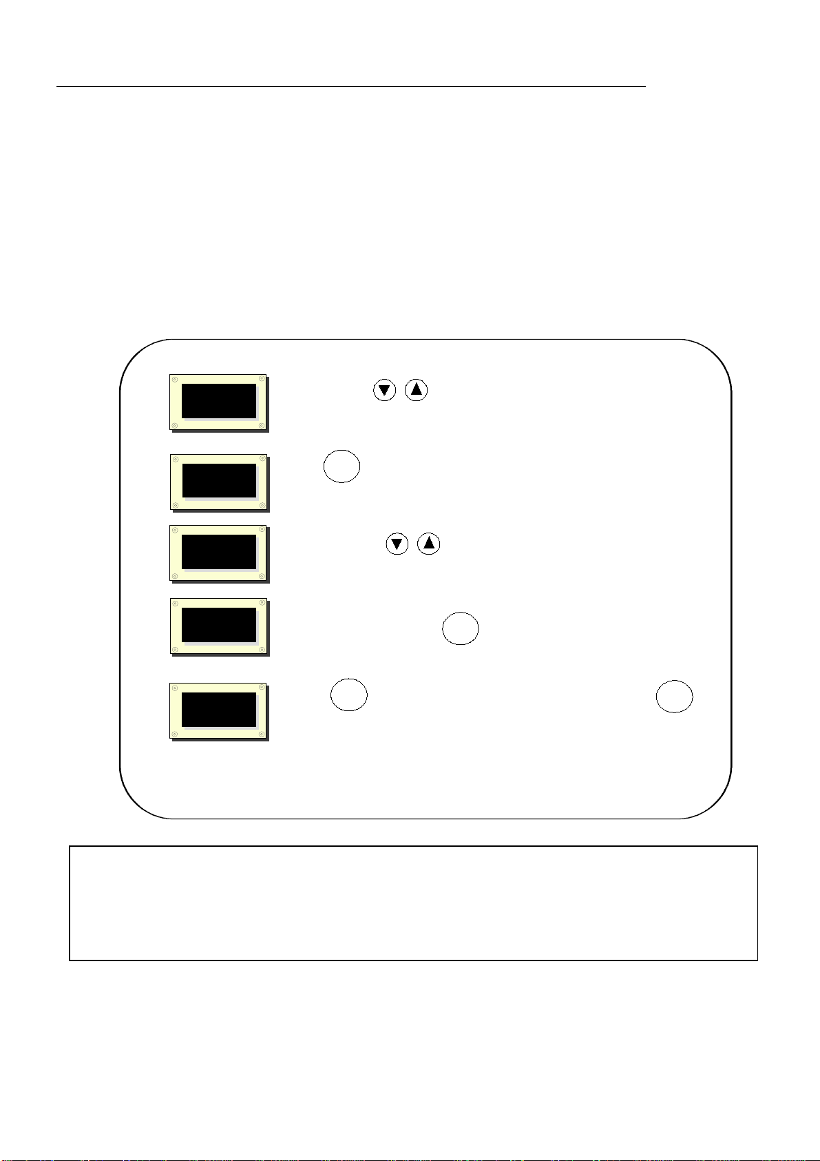
1.1 Presentation
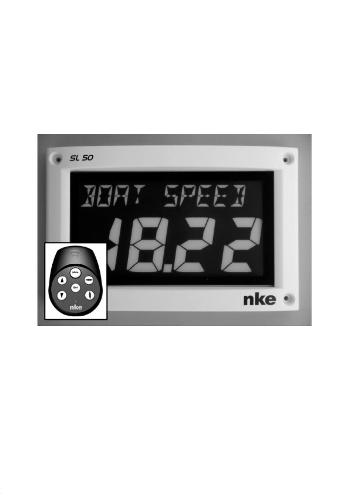
The Multifunction SL50 is a display from the TOPLINE range. Its screen, with high definition
LCD technology, offer excellent readability and a wide angle of view of the data displayed,
whether by daylight or at night. It is connected to the TOPLINE bus of your installation and
displays all the channels available on the bus.
The SL50 is controlled using either a cable remote control or a radio remote control (not
included with the product).
Channel or sub-
channel designation
Data value

- 4 – SL50 User guide – 33-60-022-000
Architecture of the installation
The presence of the equipment in the following diagram is for information only, and does not
represent the equipment of your installation.
TOPLINE bus
20-61-001
GND
DATA black
12VDC white
Figure 1
log depth interface
90-60-450
log
speedometre
depth
connection box
90-60-417
NMEA -
NMEA +
input NMEA
nke
SL50
16.85
BOAT SPEED

- 5 – SL50 User guide – 33-60-022-000
1.2 List of channels created
The master display, whether it is the SL50 or any other TOPLINE display, and each TOPLINE
sensor, automatically create their respective channels when they are connected to the
TOPLINE bus.
Channel designation
Magnetic heading
Apparent wind angle
Apparent wind speed
Depth
Surface speed
Maximum and average speed
Distance and heading to man over
board
Configuration
Bus voltage
VMG
CMG
True wind speed
True wind angle
True wind direction
Corrected heading
Estimated distance
Estimated angle
Total log
Channels created
by the
SL50
when set as
master display
Daily log
Target speed
Heading on other side
NMEA Performance
channels displayed
Optimum wind angle
Optimum VMG angle
Optimum CMG angle
Efficiency at close-haul
Polar efficiency
Bottom speed and bottom heading
NMEA channels
displayed
Cross-track error
Please note that the channels MAX SPD and AVERAGE SPD can be accessed when the SL50 is
master. By default, these channels are calculated using the surface speed, and in the absence of the
latter it will be calculated using the bottom speed. These average and maximum values are calculated
from the last power-up of your installation. You can reset these channels to zero, without switching off
the bus : select the channel MAX SPD and AVERAGE SPD then press the key for 2 seconds.
- 6 – SL50 User guide – 33-60-022-000
1.3 Keypad functions of the remote control
-Low key and High key
These keys allow to select a different channel to the one already displayed. They also allow to
increment or decrement a data which is in the process of being modified.
-key
The remote control also enables you to control the other displays of your TOPLINE installation,
the address of which is lower than the address of the remote control. Press this key to select
the TOPLINE display, which you wish to operate.
-
Ent
key
This key allows to access the sub-channels and to validate the settings you implement. Brief
pressure on this key also allows to set the level of lighting.
-
Mob
Man Over Board key
Press this key for 5 seconds, and the function «Man Over Board» is activated. When a
speedometer and a compass are connected to the TOPLINE bus, the displays then
automatically indicate the estimated bearing and distance to reach the man over board. If your
installation only comprises a speedometer, then only the estimated distance will be displayed.
To disable the «Man Over Board» alarm, you must cut off the power supply of your TOPLINE
installation.
CAUTION : the calculation of the estimate, for the Man Over Board function, does not take into
account the drift of the boat caused by the current and the wind.
For more detailed information, please refer to the remote control user guide.
-Key
This key is useless for the Multifunction SL50.
- 7 – SL50 User guide – 33-60-022-000
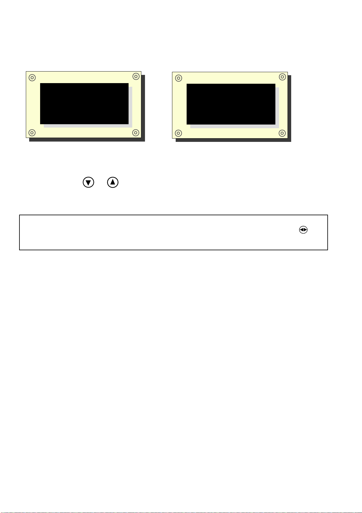
1.4 Channel selection
Using the remote control, configure the display according to your requirements. Examples of
configuration:
Procedure
-Using the keys and , you can select in the list the channel you wish to display.
-The new channel to display is recorded.
1.5 What is a sub-channel
The sub-channels are made to modify setting and display parameters of the channels. For
example, the sub-channels of the surface speed channel are:
-the offset and the calibration coefficient : setting parameters of the log-speedometer
sensor,
-the measurement unit : in knots or in km/hr,
-the filter setting,
-the setting of the upper alarm and the lower alarm.
The same applies to all channels present on the TOPLINE bus. The following chapters provide
detailed explanations on how to access the sub-channels and implement the settings.
CAUTION : if your installation is equipped with several TOPLINE displays, make sure that
the remote control controls the display which you wish to operate. Press the key
repeatedly, until the intended display blinks.
nke
SL50
16.85
BOAT SPEED
nke
SL50
30.1
DEPTH

- 8 – SL50 User guide – 33-60-022-000
1.6 Alarms setting
The setting of an alarm enables you to monitor the value of a channel. When the preset
threshold is exceeded, a warning message is displayed and an audible alarm is activated. For
example, you can set an upper threshold and a lower threshold on the surface speed channel.
The upper alarm is activated when the display is higher than the programmed threshold.
The lower alarm is activated when the display is lower than the programmed threshold.
To cancel the alarm of a channel, enter the value 0in the upper alarm and the lower alarm.
Thus, the setting of the alarms will allow you to supervise your TOPLINE installation effectively
as well as the good operation of your boat.
Note that for angular channels such as magnetic heading or wind angle, the sub-channels of
alarms are the alarm base and the alarm range.
1.6.1 Setting procedure
1
3
Press
Ent
key until the list of sub-channels
HIGH ALARM
,
to select the sub-channel
LOW ALARM
or
HIGH ALARM .
Figure 2
Then successively press
Ent
key
The new value is saved in memory.
Validate and exit the alarm menu by maintaining pressure on
Ent
.
nke
SL50
16.85
BOAT SPEED
Using the keys
from which you wish to set an alarm.
2
nke
SL50
0.00
HIGH ALARM
4
Using the keys
nke
SL50
0.00
HIGH ALARM
nke
SL50
15.00
HIGH ALARM
5
nke
SL50
16.85
BOAT SPEED
, select the channel
LOW ALARM
and
FILTERING
appears.
, set the new alarm value to
"20".
.

- 9 – SL50 User guide – 33-60-022-000
1.6.2 Alarms activation procedure
After having set the alarms, you can activate or disable all the alarms.
-Using the keys and ,select the CONFIG channel,
-Press Ent key until the sub channel valid alarm appears,
-Using the keys and , select yes or no,
-Push Ent key to validate,
-Exit the setting menu by maintaining pressure on Ent key or wait 10s and the SL50 will
automatically exit the menu.
Note that you can stop the alarm during 10 minutes with a brief pressure on any key.
1.7 Filtering of the channels
The level of filtering of a channel determines the frequency of update of the data displayed.
For example, in rough sea when the boat moves significantly, it is useful to increase the filtering
of the speed channel to stabilise the value displayed. Conversely, in calm sea, low filtering will
be preferable to obtain a fast response of the display.
Filtering is adjustable between 1and 32, and the default value is 8. The lower this value is, the
higher the frequency of update is.
Filter setting procedure
1
3
Press
Ent
key until the list of sub-channels
HIGH ALARM
,
to select the sub-channel
FILTERING.
Figure 3
Then successively press
Ent
key
The new value is saved in memory.
Validate and exit the filtering menu by maintaining pressure on
Ent
.
nke
SL50
16.85
BOAT SPEED
Using the keys
from which you wish to set the filtering.
2
nke
SL50
0.00
HIGH ALARM
4
Using the keys
nke
SL50
8
FILTERING
nke
SL50
5
FILTERING
5
nke
SL50
16.85
BOAT SPEED
, select the channel
LOW ALARM
and
FILTERING
appears.
, set the new filtering value to
"5".
.

- 10 – SL50 User guide – 33-60-022-000
1.8 Lighting setting
The SL50, as well as the other displays of the TOPLINE range, have five levels of backlighting :
0 = no lighting, 1 corresponds to the minimum level of lighting and 4 to the maximum level. You
have the option to set the level of lighting, either on the SL50 only, or on every TOPLINE
display of your installation :
1.8.1 SL50 setting procedure
-Press Ent key to enter LEVEL SETTING
-Using keys and , set the lighting level from 0 to 4,
-After few seconds the SL50 exits automatically the menu. The setting is saved in memory.
1.8.2 Setting procedure for every display of your installation
Follow the above procedure, then press on the
Ent
key to apply the setting to every display.
1.8.3 Colour setting
The SL50 offers the option of a red or a green backlighting :
-Using the keys and , select the CONFIG channel,
-Press Ent key to validate until the list of sub channels Valid alarm, language and lighting
appears,
-Then successively press Ent key to select lighting,
-Using keys and , select green or red,
-Press Ent to validate,
-Exit the setting menu by maintaining pressure on Ent key or wait 10s until the SL50 exits
automatically the menu. The new setting is saved in memory and is applied to all SL50 of
your installation.
1.9 Choice of the unit
You have the option to choose the display units of the channels:
-in knots or in km/hr for the log/speedometer,
-in knots or m/s for the anemometer,
-in degree Fahrenheit or in degree Celsius for the temperature,
-in meters or in feet for the depth finder.
Unit setting procedure
-Using keys and , select the channel from which you wish to change the unit
-Press Ent key until the sub channel Unit appears,
-Using keys and , select the unit and press Ent to validate,
-Exit the setting menu by maintaining pressure on the Ent key or wait 10s until the SL50 exits
automatically the menu. The new setting is saved in memory.

- 11 – SL50 User guide – 33-60-022-000
1.10 Choice of languages
You can configure the SL50 in one of these six available languages : French, English, Italian,
Spanish, German and Dutch.
-Using the keys and , select the CONFIG channel,
-Press Ent key until the list of Sub-channels valid alarm, language and lighting appears,
-Successively press Entkey to select the chosen language,
-Press Ent to validate,
Exit the setting menu by maintaining pressure on Ent or wait 10s until the SL50 automatically
exit the menu. The new setting is saved in memory
1.11 Zero setting of the daily log
The channels daily log and total log are at your disposal on your display.
You will use the daily log to count the number of nautical miles completed during a sailing leg.
The value is kept in memory when the power supply of your installation is cut off. Resetting the
daily log channel to zero will allow you to count the number of nautical miles of the following
sailing leg.
Zero setting procedure of the daily log
-using the keys and , select the channel daily log,
-Press until the log is set to 0.
The total log indicates the number of nautical miles completed since the installation of your
depth-finder log interface. Only a complete initialisation of your depth-finder log interface
allows to reset the total log to zero. It is performed by initialising the surface speed channel.
- 12 – SL50 User guide – 33-60-022-000
1.12 Use of the chronometer
The display includes a regatta chronometer. Times by default are T1= 6min and T2 = 4min.
1.12.1 Starting the chronometer
-Using the keys and , select the CHRONOMETER channel,
-Press
Ent
until the SL50 displays 6:00; The chronometer is ready,
-Press
Ent
to start the chronometer: then the SL50 displays “GO”
During countdown, the last 5 seconds are signalled by a BEEP, then the START signal is given
by the alarm.
Note that if you did not start the chronometer exactly at the start signal, you can synchronise
the chronometer countdown at T2 by pressing the Ent key. During the procedure, you can also
return to the initialisation value by pressing the Ent key for 2 seconds. The chronometer
displays T1 = 6.00 minutes, for a new start.
1.12.2 Setting of T1 and T2
This setting can only be performed on the master display of your installation.
−select the CHRONONOMETER channel, using the and keys,
−press
Ent
until the message T1 setting appears,
−change the value of T1 using the and keys, then confirm with
Ent
,
−the message T2 setting appears,
−change the value of T2 using the and arrow keys, then confirm with the
Ent
key,
after 5 seconds, the SL50 will automatically leave the setting mode.
- 13 – SL50 User guide – 33-60-022-000
2 CALIBRATION OF SENSORS
Every nke sensor is adjusted at the factory. However, a calibration is required to adapt the
sensor to the specificities of your boat and to obtain an optimum measurement accuracy.
Follow the calibration procedure below, by visualising the settings on a display.
Please refer to the installation notice of the TOPLINE sensor that you wish to calibrate.
2.1 Setting procedure of calibration coefficient
Example : you wish to set up the calibration coefficient of the boat speed channel at this value :1.1.
2.2 Offset setting procedure
Follow the above procedure and choose the OFFSET sub-channel.
Note that this value is set to 0.
1
2
Using the keys
3
4
Figure 4
Press
The calibration is saved in memory.
Ent
Then successively press to select the sub-channel
CALIB COEF.
nke
SL50
kts
UNIT
nke
SL50
1.00
CALIB COEF
nke
SL50
16.85
BOAT SPEED
select the cannal from which you wish to select the calibration coeficient.
until the list of sub-channels
UNIT, CALIB COEF
and
OFFSET
appears.
Ent
nke
SL50
16.85
BOAT SPEED
Ent
Press to validate and exit by maintaining pressure on . .
Ent
nke
SL50
1.00
CALIB COEF
Using the keys
change the new calibration coefficient to
"1.1"
.
5
CAUTION :
-The calib coef parameter is a multiplier coefficient. This value must never be equal to
zero. By default this coefficient is set to 1.00. If it is not the case, before starting a
calibration enter the value 1.00.

- 14 – SL50 User guide – 33-60-022-000
2.3 Autocompensation of the fluxgate compass
Please refer to the compass user manual before starting the autocompensation procedure.
In order to achieve a successful autocompensation, you must navigate :
-On smooth sea, with no current and no wind.
-Away from large magnetic masses such as cargo boats.
-In an open area allowing the execution of a circle with a diameter approximately 5 times the
length of the boat.
-At a constant speed of about 2 or 3 knots.
Procedure
1. Select the magn head channel,
2. Start to describe the circle, then press the 2 second on the key ▼, to launch the
autocompensation procedure.
3. One single circle*is sufficient to perform the autocompensation correctly, when its a
success, the message 3000 is indicated.
* For the previous generation of compass, referenced as 90-60-005, at least three circles
must be executed.
In case of problem during autocompensation, the SL50 displays the PAN message , plus one
code :
-Code 1 : cancellation at user request.
-Code 2 : detection of a gyration in the opposite direction. Start again clockwise.
-Code 3 : excessive variation between 2 heading measurements. Reduce the speed of your
boat to 2 or 3 knots.
-Code 4 : angle correction higher than 20°. Start the autocompensation procedure over.
In case of autocompensation error, the measurements are not saved to the memory and the
sensor resumes its normal operating mode.
2.4 Technical specifications
-Power supply : 10 to 16VDC
-Consumption : 20mA without lighting and 70mA with lighting.
-Tightness : IP67
-Weight : 1.150kg including cable
-Dimensions : height = 260mm ; width = 156mm ; thickness = 45mm
-Operating temperature : -10°C to +50°C
-Storage temperature : -20°C to +60°C
-Horizontal viewing angle : superior to 120°
-Vertical viewing angle : superior to 90°
Height of the characters displayed : 50 mm for the channel, and 10 mm for the identifier and the
unit.

- 15 – SL50 User guide – 33-60-022-000
2.5 Version and address number of the display
You can check the software version of the display and its address in the list. In order to do that,
select the CONFIGURATION channel, then press the Ent key for 5 seconds. The date, time
and version of the SL50 software are then momentarily displayed on the screen.
To check what the version of your software is, select the CONFIG channel and press Ent key
until “nke SL50” is displayed: The date, time and version of the SL50 software are then
momentarily displayed on the screen. To read the address number , select the CONFIG
channel and press the key for 3 seconds.
2.6 Diagnostic for 1st level troubleshooting.
Before contacting technical support, please check the troubleshooting table below.
Problem Possible causes and solutions
The Topline installation does not detect the SL50
The bus cable is not or is badly connected to the terminal box : check the
plugging and the connection inside the terminal box. Check the state of
the cables : they must not show any sign of wear or cut.
The remote control does not control the SL50 The address of the remote control is lower than that of the SL50 :
reinitialise the remote control, see chapter 17.
The SL50 is set at the address « 0» : perform its initialisation, see
chapter 17.
The SL50 displays the message « data wire error » Check that the black data wire is connected at the right location in the
terminal box : see chapter 17
The SL50 displays the message « collision error » It is possible that there are two master displays (at address 1) on your
installation : check the addresses, if it is the case, reinitialise one of the
displays.
The SL50 does not display the NMEA data : that from the GPS
for example.
Has the NMEA link been initialised ? see chapter 16
The NMEA link is not or is badly connected to the terminal box : check
the connection of the SL50 and that of the NMEA transmitter (GPS).
Your display indicates battery fault. Check the voltage of your battery with a voltmeter : the operating voltage
must be higher than 10VDC. Check the charge behaviour of your battery.
If you do not manage to solve the problem, please contact your distributor.
2.7 SL50 initialisation : see chapter 4.8

- 16 – SL50 User guide – 33-60-022-000
3 INSTALLATION
This chapter describes the installation and the initialization of the SL50.
IMPORTANT
-Read this user guide entirely before starting the installation.
-Any electrical connection of the SL50 on the TOPLINE bus must be carried out with the
terminal box 90-60-417 (equipped with a connection terminal for the NMEA input).
-Only use TOPLINE bus cable of the type 20-61-001.
-Any intervention on the TOPLINE bus must be carried out with the installation power
switched off.
3.1 Packing list :
-one Multifunction SL50 equipped with ten meters of cable, including the TOPLINE bus and
one NMEA input,
-one user guide,
-one protective cover
-four M4 fixing screws
3.2 List of accessories
-Standard terminal box TOPLINE bus : 90-60-121
-Terminal box TOPLINE bus with NMEA input : 90-60-417
-Cable remote control : 90-60-245
-Wireless remote control : 90-60-258
3.3 Installation precautions
The location of the SL50 must be :
−so that the helmsman is able to easily read the data,
−placed in a location away from potential shocks,
−more than 40cm away from a magnetic compass,
−more than 1 meter away from a VHF radio transmitter.
The best readability of the SL50 is generally obtained by mounting it on a mast foot support.
You can also wall mount it on any flat surface of the boat.
Four M4x30mm fixing screws are provided with the SL50.
The support is an accessory available at your distributor.

- 17 – SL50 User guide – 33-60-022-000
3.4 Mounting on mast foot support
Make sure that the support you have chosen can be mounted on the mast of your boat. Check
that there is sufficient space behind the partition to make the cable run.
If the cable runs inside the mast, make the cable pass through an opening equipped with a
grommet. If the cable runs across the deck, make the cable pass through a tight stern tube
gland.
3.4.1 Mounting procedure for the support
-place the support on the mast foot,
-using a pencil, locate the six fixing holes, then remove the support,
-using a centre punch, mark the centre of each hole,
-drill the holes with a diameter ∅5,
-mount the support with the six fixing screws or six rivets (not included).
3.4.2 Mounting procedure of the SL50 on the support
-drill a ∅18 holes in the support (as indicated on Figure 5)
-Clean the mounting surface with alcohol,
-introduce the cable in the ∅18 drilled hole,
-position the SL50 so that it faces the four ∅4 holes,
-place the four screws (provided with the product) in the holes, from the back of the partition,
-tighten the four fixing screws moderately.
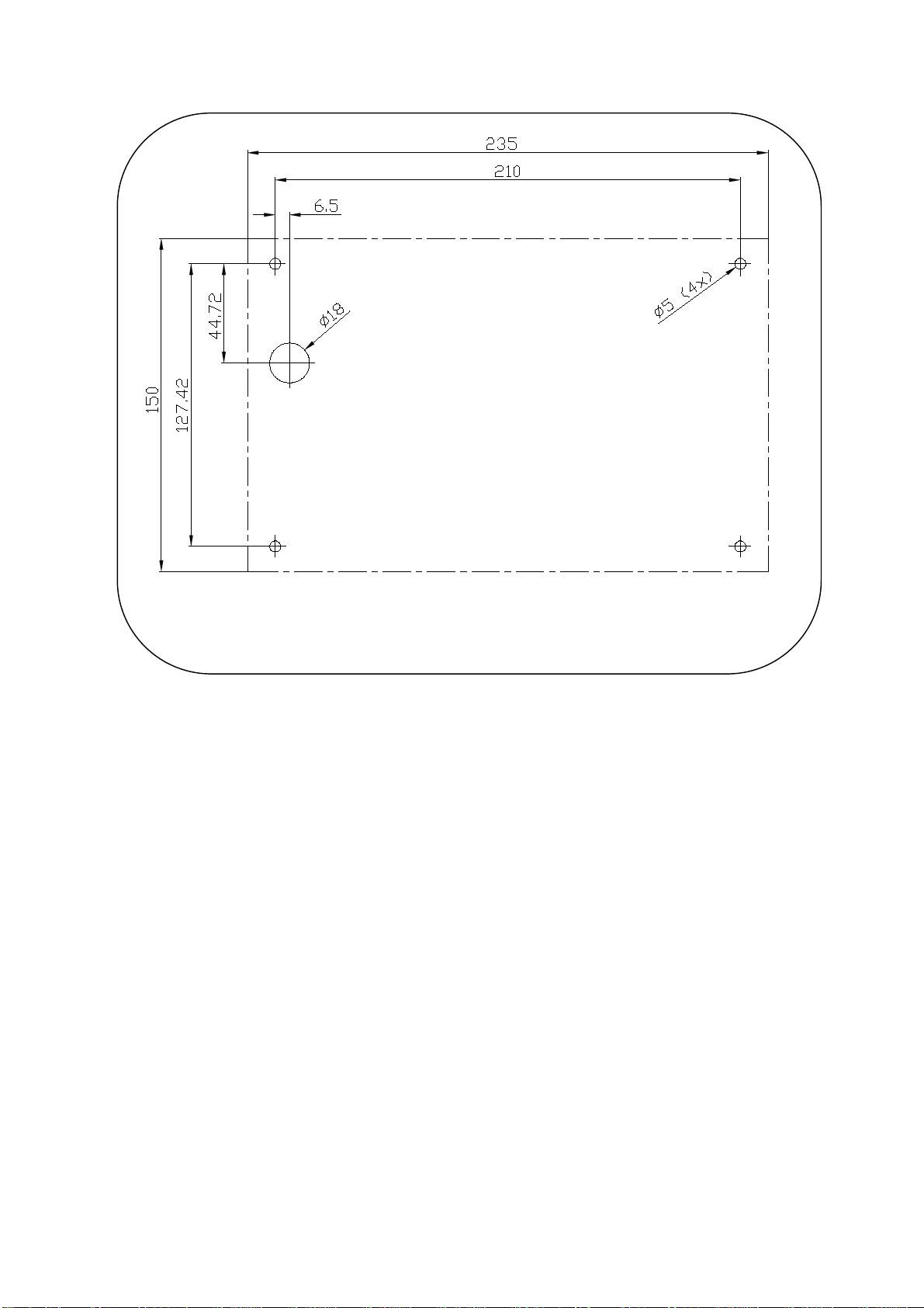
3.5 Wall mounting
Make sure the location is clean, smooth and flat. Check that there is sufficient space behind the
partition to make the cable run.
Procedure
-Perform the drillings of figure 13 on the partition,
-Clean the mounting surface with alcohol,
-Lay a very thin silicone sealing joint around the mounting perimeter,
-introduce the cable in the ∅18 drilled hole,
-position the SL50 so that it faces the four ∅5 holes,
-place the four screws (provided with the product) in the holes, from the back of the partition,
tighten the four fixing screws moderately.
CAUTION :
-When mounting the SL50, tighten the fixing screws moderately. Excessive tightening
can cause the casing to break.
-Do not use glue putty to mount the SL50.
- 18 – SL50 User guide – 33-60-022-000
Figure 5
- 19 – SL50 User guide – 33-60-022-000
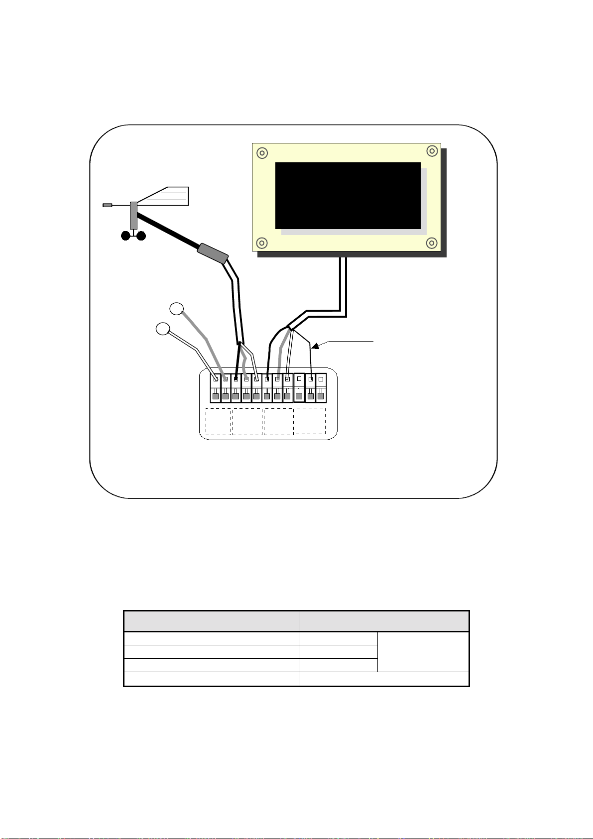
3.6 Connection to the Topline bus
1. Make the bus cable run from the SL50 to the TOPLINE terminal box of your installation.
2. Connect the bus cable inside the terminal box.
If you reduce the length of the bus cable, strip and galvanise the wires before connecting them
inside the terminal box.
3.7 Identification of the cable wires
White cable 6 wires Wire identification
White wire +12V
Black wire Topline Data
Braid Earth
TOPLINE Bus
Red wire Initialisation wire (GND)
BLANC
GND
NOIR
BLANC
GND
NOIR
12V
gnd
BLANC
GND
NOIR
supply 12Vdc
boîte de connexion
90-60-121
-
GND
DATA black
12VDC white
Figure 6 : connection to TOPLINE bus
+
nke
SL50
16.85
VITES SURF
init wire : red

- 20 – SL50 User guide – 33-60-022-000
3.8 SL50 and remote control initialisation
At first power-up, you must initialise the SL50 so that an address is assigned to it. The display
is delivered with the address set as 0. During the initialisation, it will automatically insert itself in
the list of instruments and displays of the TOPLINE bus of your installation :
−either as master, at the address 1,if this address is available on the bus,
−or as slave, if the address 1 is taken by a master, at an available address comprised
between 2and 20.
Likewise, the remote controls must also be initialised. Please refer to the remote control user
guide.
3.8.1 Initialisation procedure: the SL50 is set at the address 0
-your installation is powered off : disconnect the initialisation red wire from the init terminal
(GND),
-power up your installation : the SL50 then performs an auto-test,
-when the message «connect the red wire» appears, reconnect the red wire on init (GND) :
the SL50 takes an address available on the bus,
-the SL50 is then initialised.
3.8.2 Reinitialisation procedure : the SL50 already has an address between 1 and 20
You may need to reinitialise the SL50, for example to have another address assigned to it.
-your installation is powered off : disconnect the initialisation red wire from the init terminal
(GND),
-power up your installation : the SL50 performs an auto-test then takes the address 0,
-when the message «connect the red wire» appears, reconnect the red wire on init (GND) :
the SL50 takes an address available on the bus,
-the SL50 is then initialised.
CAUTION :
−the remote control(s) of your installation must be assigned to an address higher than the
one of the SL50. To achieve that, you must first initialise the SL50 then the remote
control(s).
This manual suits for next models
1
Table of contents
Popular Boating Equipment manuals by other brands


autobimini
autobimini lite Installation and user manual

Suprod
Suprod ET200 installation manual

Sea Eagle Boats
Sea Eagle Boats QuikRow instructions

Classic Accessories
Classic Accessories StormPro Instructions & Care

Bellmarine
Bellmarine OutboardMaster pro user manual

MAKE A WAKE MARINE
MAKE A WAKE MARINE Pro2 T-Top installation guide


