autobimini lite User manual

Version 1.0
Installation and User’s Manual

Version 1.0
Table of Contents
About this Manual ................................................................... 1
Safety........................................................................................ 2
System Components............................................................... 3
Installation Planning ............................................................... 7
System Installation................................................................ 10
General Operation ................................................................. 23
Care and Maintenance .......................................................... 24
Troubleshooting .................................................................... 25

1
About This Manual
Version 1.0 created 2/2/2022
This manual was created for use by FFI Automation end users and OEM customers. OEM customers
are encouraged to use material they deem appropriate for incorporation into their own end-user manual.
Contact FFI Automation directly if you have questions, suggestions, or corrections to the manual.
2
Safety
FFI Automation considers safety of its customers and end users of prime importance. Please read and
follow the warnings and recommendations below to ensure correct and safe operation of the system.
Operate Safely
Before operating autobimini lite, thoroughly inspect the area around autobimini lite to verify that all
passengers are in a safe position. Verify that no person is in an area that will interfere with the motion of
the autobimini lite as serious injury could result.
Pinch Points
Moving parts, including autobimini lite arms can pinch, cut, or crush. Keep passengers clear and use
caution when operating the unit.
Operation Limitations
The autobimini lite actuators are designed to overcome wind loads in order to operate in adverse weather
conditions. However, do not operate autobimini lite in excessive high winds or boat speeds. High winds
and boat speeds could result in product damage and/or personal injury. Do not attempt disassembly or
repair while the boat is in motion.
Maximum Speeds
Observe the autobimini lite maximum operating speed limits. The maximum speeds are relative values
inclusive of wind and boat speeds combined.
autobimini lite Position
Maximum Speed
Full UP Position
25MPH
Full UP Position (Front Support Arms down)
35MPH
RADAR Position
50MPH (boot installed)
Full DOWN Position
70MPH (boot installed, highway speed)
Caution: Do not operate autobimini lite in excessive high winds
Electrical hazards
There are no end-user serviceable components on the autobimini lite contactor or within the actuators.
Users should consult their dealer for repairs or replacements if autobimini lite is damaged in any way,
including water immersion.

3
System Components
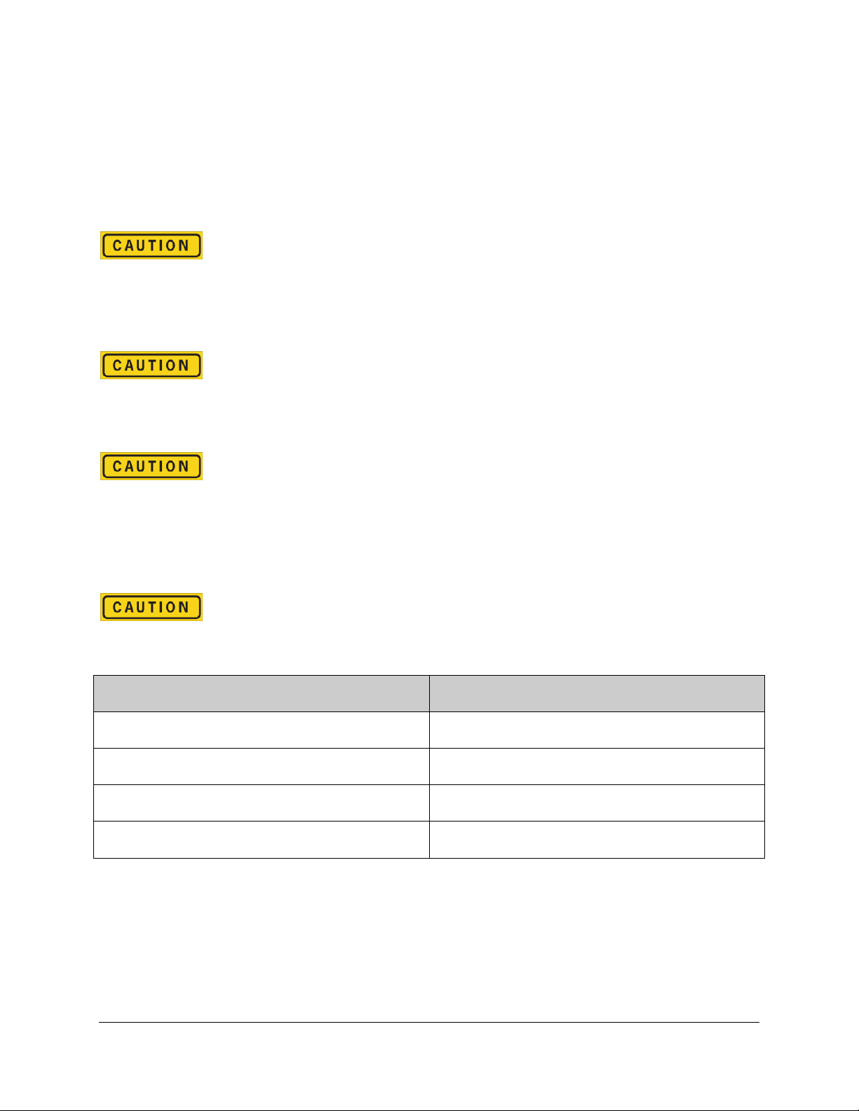
autobimini lite Contactor
autobimini lite DC Reversing Contactor
autobimini lite 12VDC reversing contactor key features:
•Heavy Duty: 12VDC @ 50A continuous ratings.
•Integral Switch Terminals: The contactor has on-board terminals for connections to
momentary console switch.
•Marine Grade Terminals: Brass bolts with nuts, washers and lock washers hold the battery
and motor connections.
•Waterproof: IP65 rated construction to handle marine environments
4
Heavy Duty Marine Grade Construction
•Dual actuators with stainless steel yoke.
autobimini lite intelligent actuator
•Significantly heavier and more durable than competing brands.
•4-bow sand blasted aluminum frame and stainless steel fasteners.
•Worm Gear Technology: The built in worm gear inside the smart actuators protects the
system from back-driving to ensure safe and reliable operation.
•UHMW: Ultra High Molecular Weight film provides frictionless aluminum frame sliding for
years of maintenance free operation.
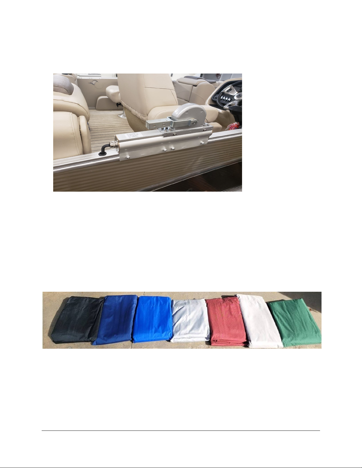
•UV protected and 600D solution dye canvas with double PTFE Teflon sewing and marine
grade zippers.
autobimini lite canvas colors (Black, Navy Blue, Pacific Blue, Silver, Burgundy, Beige and
Green. Supplied with matching zippered boot.
•Matching storage boot with marine grade zippers.
•Marine grade wiring with tinned copper wire.

5
Battery Powered: The autobimini lite operates on 12VDC battery power.
Resettable Circuit Breaker: The autobimini lite has built-in automatic reset circuit breaker protection.
The circuit breaker will stop motion when the bimini moves to the hard UP and DOWN positions.
autobimini lite automatic reset circuit breaker
Adjustable Width: Telescoping frame adjusts to fit 92” to 102” wide pontoon or deck boats.
Premium Coverage: UV protected autobimini lite canvas top with generous 10 foot coverage.
Console Switch: Momentary console switch mounted in the helm control panel to operate the contactor
that drives the motors up and down.
autobimini lite console switch with marine grade wiring
6
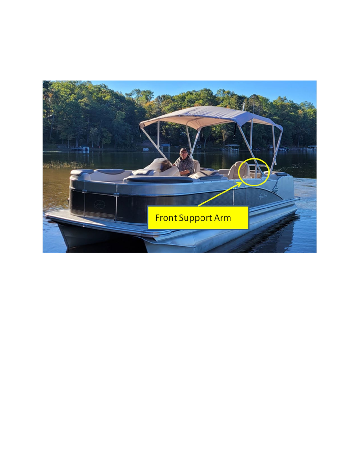
Front support arms: Two (2) front support arms are standard providing stability to the bimini frame
and hard stop up position.
Front support arms are standard on autobimini lite
7
Installation Planning
This section describes what the end installation looks like and preparation knowledge.
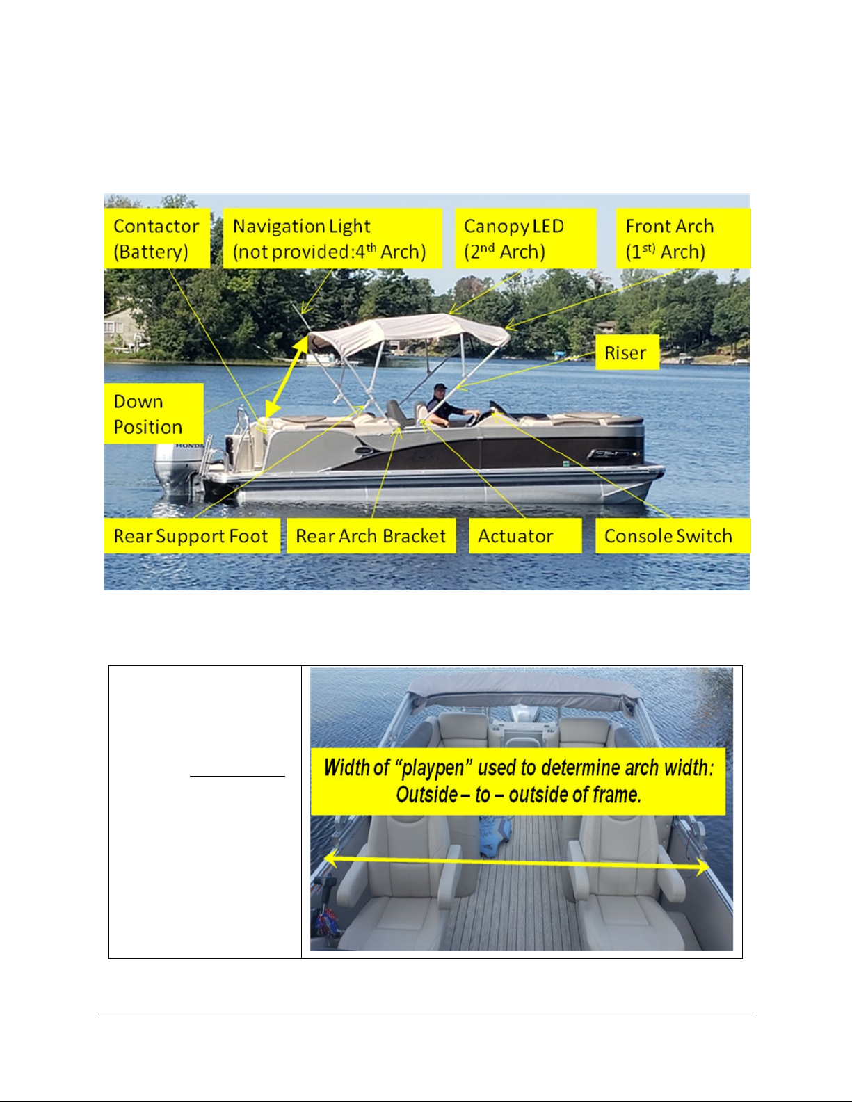
Installation with component names and relative locations
Planning for installation:
1. The 1st, 2nd, 3rd and
4th ARCHES and
RISERS are
assembled into sub-
assemblies based on
the playpen width.
The risers connect
to the arches using
the supplied
connector tubes.
8
2. The DOWN POSITION is where the 4th arch would rest with the rear support foot installed.
Pick a location that is clear from passengers and similar to the bimini being replaced as typical.
3. The NAVIGATION LIGHT is not provided. The existing navigation light is used and wires
routed through the 4th arch and riser. The autobimini lite canvas and boot has provisions (sewn
holes) to support the navigation light installation. Cable grommets for wire routing are provided
in the aluminum frame.
Navigation light installed on 4
th arch. Access holes are built into canvas and boot
4. The autobimini lite REVERSING CONTACTOR should be mounted near the battery. The
circuit breaker needs to be within 7 inches of the battery positive (+) post based on marine
electrical codes.
5. The REAR ARCH BRACKET mounting location determines how far the front(1st arch) travels
down. The closer the rear arch bracket is to the actuator, the further down the bimini front or
1st arch will travel. Pontoon boats do not travel “flat”. Thus, the user can select the desired
position.
6. Two ACTUATORSare provided. The marine grade actuator cable provided has:
a. Two (2) motor power wires of sufficient gauge to reduce voltage drop.
b. Enough marine grade cable to run inside the playpen and underneath the pontoon to the
contactor location. Attention to routing the actuator cable is suggested prior to
installation. The marine grade cable doesn’t have to route inside the playpen aluminum.
7. The CONSOLE SWITCH is a momentary switch. The console switch allows for pushbutton
operation at the control console located in the helm.
8. The most difficult installation tasks are:
a. Locating the actuators in the correct position. Clamps can be used to ensure the
mounting location is correct before drilling any holes. Wiring and operating the actuators
before a final installation is suggested to ensure correct and proper operation before
routing all the wires through the pontoon.

9
Expert Tip: Protective cloth can be used to prevent scratches when mounting the actuators or
brackets until the final mounting locations are determined.
b. Routing the wiring for the actuators and console switch should be reviewed in advance.
Typically, the pontoon will have existing wire path ways on both sides of the pontoon
from existing electrical wiring and cabling. Investigate the best path to run the wires
underneath the pontoon and secure wires near aluminum supports with cable ties (or
other wire securing devices). Cable ties or other wire securing devices are not provided.
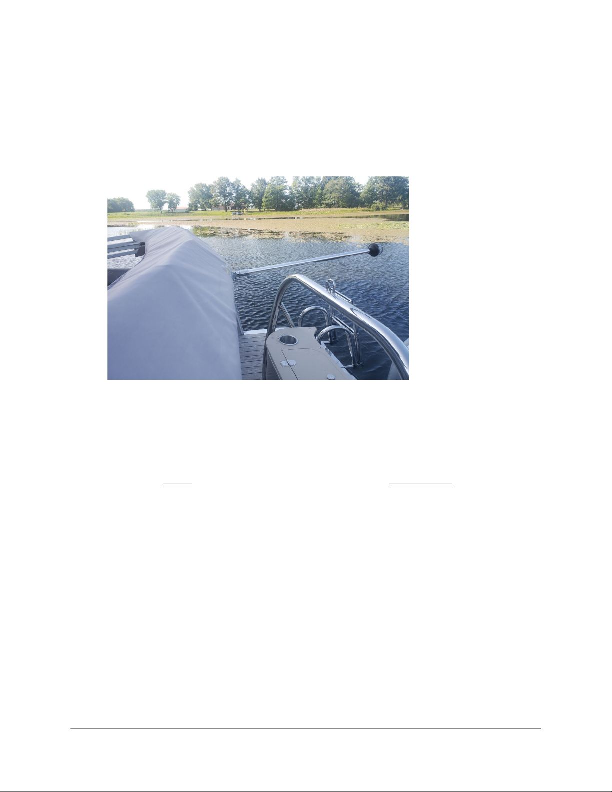
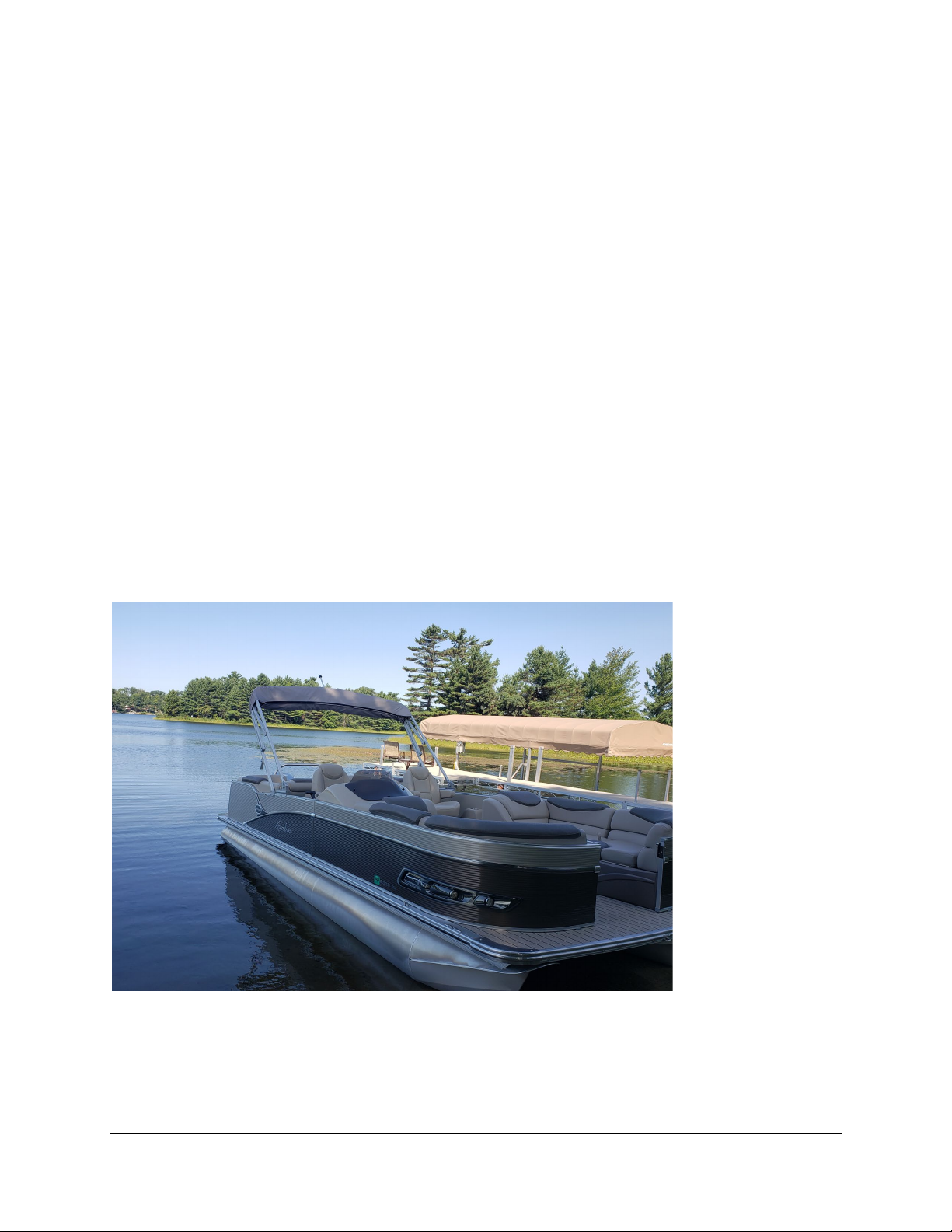
autobimini lite in full up position
Expert Tip: autobimini lite videos available on our YouTube channel at:
www.youtube.com/channel/UCpATtpEzl15J6B5WQWU-PgA.
Expert Tip: Additional pictures located at: www.autobimini lite.com/gallery.
10
System Installation
This section describes how to install the system including mechanical assembly, electrical assembly and
suggested order of assembly.
The general assembly process is as follows:
1. Gather and identify the components to be installed.
2. Remove any existing bimini.
3. Assemble the autobimini lite aluminum frame.
4. Mount the stern navigation light.
5. Mount the actuators.
6. Clamp the rear arch support brackets and attach 3rd and 4th arches.
7. Locate and wire the autobimini lite reversing contactor.
8. Install console switch.
9. Install arches.
10. Attach the canopy.
11. Set the rear arch support brackets’ final locations.
12. Install the rear support feet.
13. Hold-down snap installation (optional).
14. Install front support arms.
15. Wire navigation light
Radar position
11
Installation
1. Gather and identify the components to be installed. At a minimum this will include:
•Two motor actuators with their mounting brackets and wiring
•Two rear arch mounting brackets
•Four riser arms
•Four bimini arches
•Eight arch connector tubes
•Two front support arms
•One autobimini lite reversing contactor
•Automatic reset circuit breaker and cabling
•Console switch with marine grade cable
•Assembly hardware
•Tools (tape measure, portable drill, file, lube, socket set, screwdrivers, cloth, wire strippers,
pencil)
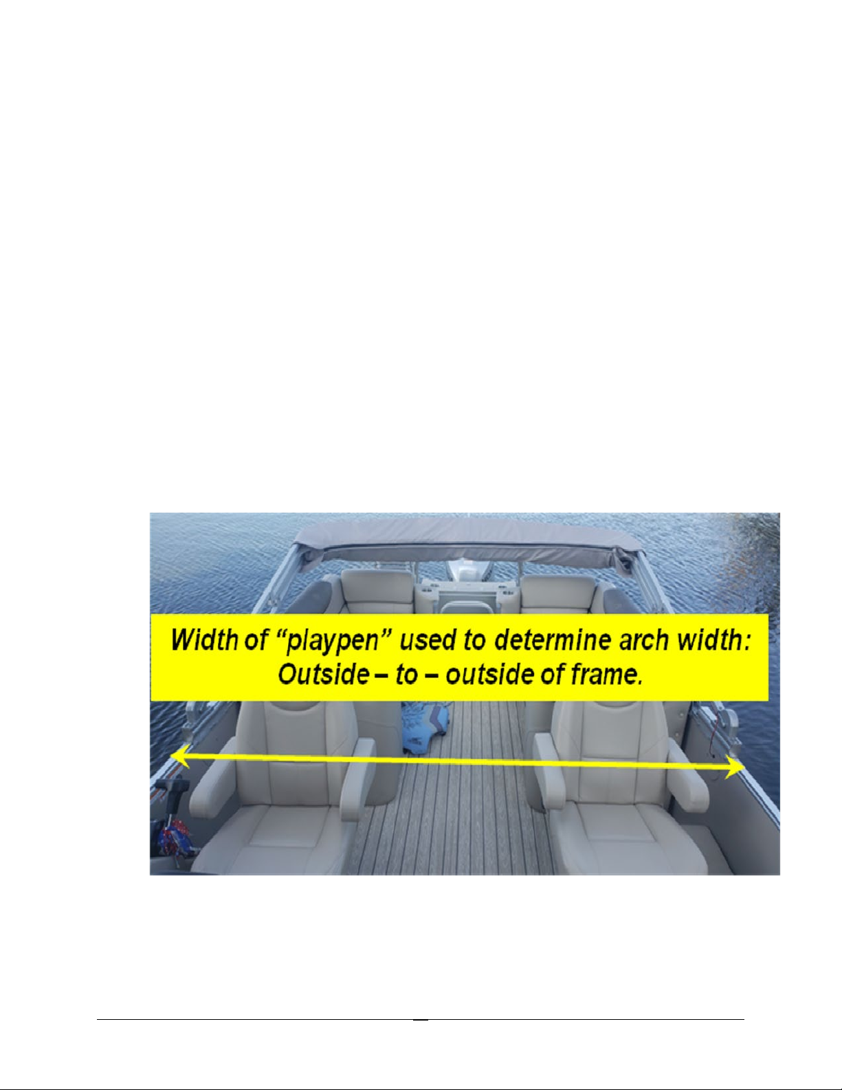
2. Remove any existing bimini.. Note the location of the bimini mounting points. This may aid
in locating the placement of the new autobimini lite.Measure the width of the “playpen” –
outside frame to outside frame – at the points where the new autobimini lite will be attached. See
image below.
Measure the width of the pontoon playpen. This determines the aluminum frame arch
width for assembly. Shown in down position with arches layered

12
3. Assemble the autobimini lite aluminum frame.
a. Deburr the outside ends of the insert tubes as well as the inside edges of the riser arm
tubes and the inside edges of the arches – this will greatly ease assembly.
b. Install the predrilled portion of the connector tube into the riser arm and bolt this
connection with one of the 10-24 x 1-1/2” bolts with nylon locknut.
c. Create the arch assembly by inserting each side of the riser/insert into an arch (lightly
greasing the insert first may aid in smooth insertion). Adjust the insertion depth such that
the overall width of the assembly equals the width measured in step 2. The exposed
insert tube will usually be approximately 4 inches – see the image below.
d. Drill and bolt this connection together using a 3/16” drill bit and the corresponding
hardware. There should be four bolted connections per arch.
e. Repeat this assembly for each of the four arches, except for the 4th arch (stern) which
will have the navigation light.
Arch – connector tube - riser arm assembly shown bolted together
4. Mount the stern navigation light.
a. Use the provided hardware to attach the existing navigation light to the rearmost frame
arch (4th arch).
b. Route the wire through the arch, then through the riser frame after drilling the bolt holes
but before assembling the arch. This will be the easiest way to route the wire through the
frame.
c. Use a “fishing wire” as necessary to properly route the wire to the bottom of the riser.
Expert Tip: Drill holes in the aluminum tubing before routing navigation wire.

13
autobimini lite with navigation light installed in 4
th arch
5. Mount the actuators.
a. Place the front arch where it will sit when folded down. Make sure the folded bimini will
rest at the desired stern location.
b. Note the location at the base of the riser where the actuator is connected and mark the
boat frame. Make a similar mark on the opposite side of the boat at an equal distance
from the stern.
c. Align the actuator receiver location with the mark made in step ‘b’ such that the front
arch will end up in the desired location.
d. Make sure the actuators are tightly pressed to the top of the boat frame.
e. Using the actuator holes as a guide, drill 1/4” holes through the boat frame.
f. Mount the actuators by bolting them to the frame using the provided hardware.
Slide riser arm onto actuator receiver to determine actuator mounting position
Expert Tip: When drilling holes in the playpen frame, check for existing wires before drilling.

14
6. Clamp the rear arch support brackets and attach 3rd and 4th arches.
a. Temporarily clamp the front of the rear arch support brackets to the “playpen” about 3
inches from the rear (stern end) of the actuator.Protective cloth can be used to prevent
scratching the surface of the playpen.
b. Attach the 3rd and 4th aluminum frame assemblies to the rear arch support brackets using
the supplied stainless steel hardware. Do not bolt the rear arch support brackets to the
boat playpen at this time. They will be bolted after the final position adjustments have
been made.
Important:DO NOT REMOVE the UHMW frictionless tape on the 3rd risers. This prevents
wear between the aluminum frame assemblies when folded down.
7. Locate and wire the autobimini lite reversing contactor.
a. Locations near the battery are typical for the reversing contactor.
b. Run the battery power wires to the autobimini lite contactor using the circuit breaker
connection wire.
Important: The automatic reset circuit breaker protection must be located within 7 inches of the
battery positive (+) post to comply with marine safety guidelines and electrical codes.
Expert tip:Wire the autobimini lite contactor and actuators without routing the wires to learn
terminal connections in an easy and open environment.
autobimini lite reversing contactor located near the battery
15
c. Route the actuator wires from the contactor to the actuators. This will likely require
routing across the bottom of the boat platform and through the playpen frame.
Choosing how to route the wires is dependent on each individual installation as every
pontoon is unique. Use common sense to obtain a safe and clean wire installation free of
sharp edges. The actuator wires can be run below, through, or on top of aluminum frame
members, using zip-ties as necessary for a clean installation.
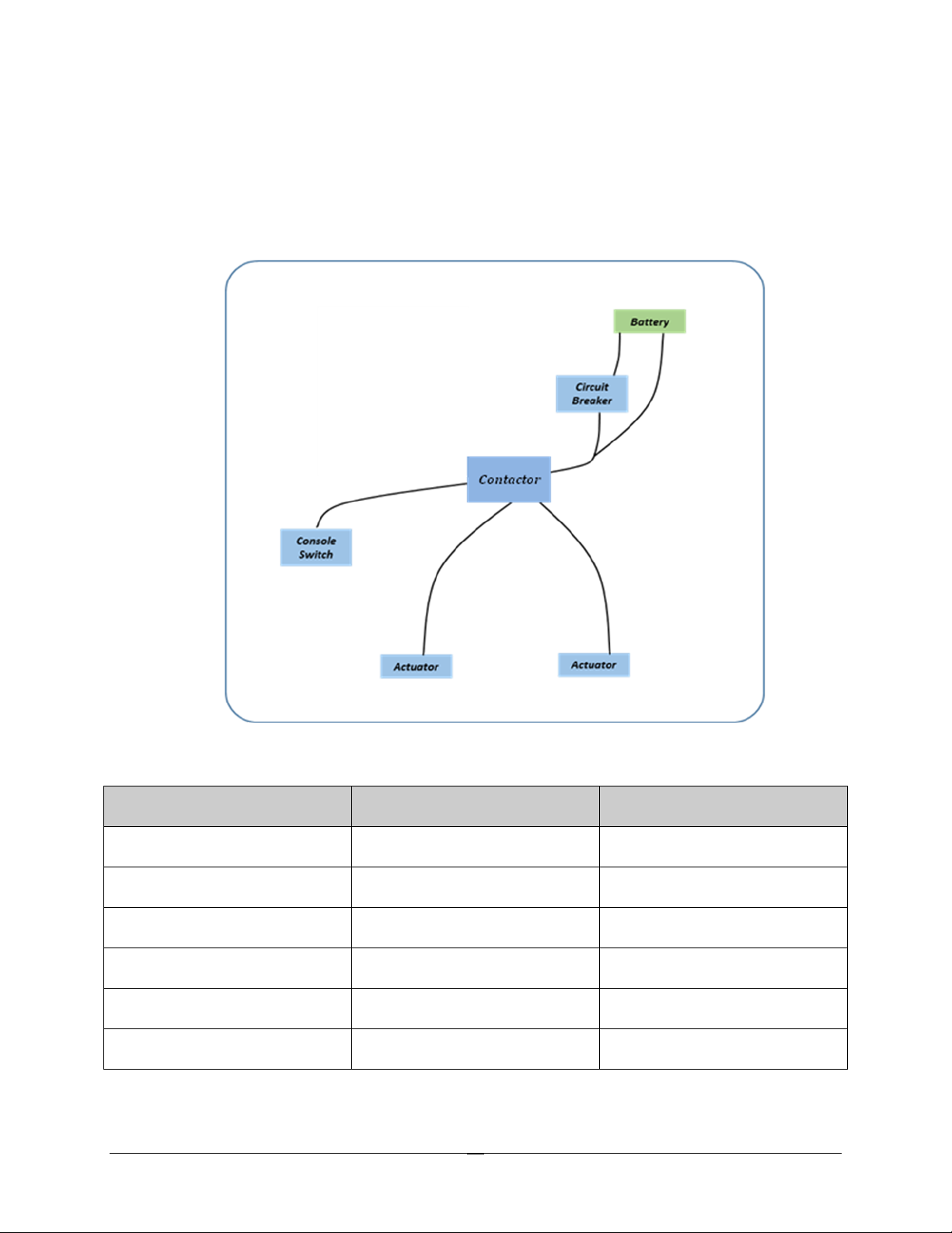
autobimini lite wiring block diagram
Contactor Power Wire Connection Table
Wire & Function
Wire Color
Device Connected
Contactor Power +
Red
From Circuit Breaker (B+)
Contactor Power -
Black
From Battery (B-)
Contactor Actuator +
Red
From actuator 1
Contactor Actuator -
Black
From actuator 1
Contactor Actuator +
Red
From actuator 2
Contactor Actuator -
Black
From actuator 2
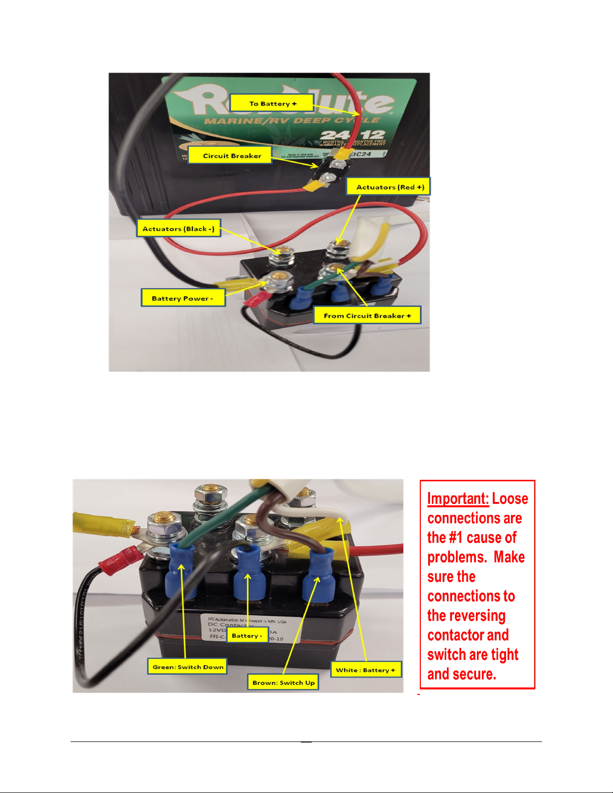
16
Contactor wiring connections
8. Install console switch.
a. Insert the free end of the console switch wire through the console, pulling the length
through, and snapping the switch in place.
b. Route the wire appropriately from the console to the contactor location.
c. Make the electrical connections to the contactor.
Reversing contactor console switch wiring

17
9. Install arches.
a. Press DOWN on the switch, 1 second at a time, until both actuator yokes are resting on
the actuator frame creating a hard stop position to synchronize the actuator movements.
b. Now use UP on switch to move the actuator yokes to an approximately vertical position
that will permit the 1st and 2nd riser arms to be installed..
c. Install the aluminum frame assemblies onto the actuator receivers.
d. Bolt the 1st and 2nd aluminum frame arches to the actuator receivers. Use the supplied
stainless steel bolts and nuts.
autobimini lite actuator installed, shown with wire routing
Expert tip:Install and leave the UHMW tape on the 3rd risers. This allows the aluminum frame
to slide frictionless for years of operation without wear.
UHMW (ultra high molecular weight) film allows frictionless sliding

18
10. Attach the canopy.
a. Use the console switch to set the arms about halfway up.
b. Starting at the front or 1st arch. Attach the canopy by zipping it to the respective
aluminum frame members. Subsequently, attach the canopy by zipping it to the 2nd, 3rd
and 4th arches. Actuate the arms forward with the switch as necessary to more easily
reach all arches.
autobimini lite installation (shown without front support arms installed)
11. Set the rear arch support brackets’ final locations.
a. Raise the autobimini lite to its fully-extended position. Be careful to not over-extend
the canopy since the front support arms are not installed yet. It is possible to
damage the canopy or frame if it is over-tightened.
b. Make sure the front 1st arch ends up at the final desired location. If it is too far forward,
then lower the bimini, move the rear brackets toward the stern and retest. If too far back
then lower the binimi and adjust the rear brackets to be closer to the actuators. Repeat
this sequence until the front of the bimini ends up in the desired location. The REAR
ARCH BRACKET mounting location determines how far the front or 1st arch goes
down. The closer the rear arch bracket is to the actuator, the further down the bimini
front or 1st arch will travel. Pontoon boats do not travel “flat”. Thus, the user can select
the desired position. Keep in mind the desired tightness of the canopy as well.
c. Drill and bolt the rear brackets to the boat frame using the brackets as the drilling guide.
Expert tip:Check the angled foot on the riser where it meets the rear arch bracket. The angled
foot makes contact with the bracket surface to assist in tightening the canvas.
Table of contents


