NKK SWITCHES IS-CHPMP User manual

IS-CHPMP and IS-CHPMPHP Manual
7850 East Gelding Drive • Scottsdale, AZ 85260-3420
IS-CHPMP and IS-CHPMPHP Manual D.docx Page 1 of 10
Toll Free 1.877.2BUYNKK (877.228.9655) •Phone 480.991.0942 • Fax 480.998.1435
www.nkkswitches.com • Email engineering@nkkswitches.com 1120
IS-CHPMP and IS-CHPMPHP Manual
Revision D
NKK SWITCHES
7850 E. Gelding Drive
Scottsdale, AZ 85260
Toll Free 1-877-2BUYNKK (877-228-9655)
Phone 480-991-0942
Fax 480-998-1435
e-mail <e[email protected]>
All Rights Reserved Worldwide
NKK Switches makes no warranty for the use of these products and assumes no responsibility for any errors,
which may appear in this document, nor does it make a commitment to update the information contained herein.
Smart Switch is trademark of NKK Switches.

IS-CHPMP and IS-CHPMPHP Manual
7850 East Gelding Drive • Scottsdale, AZ 85260-3420
IS-CHPMP and IS-CHPMPHP Manual D.docx Page 2 of 10
Toll Free 1.877.2BUYNKK (877.228.9655) •Phone 480.991.0942 • Fax 480.998.1435
www.nkkswitches.com • Email engineering@nkkswitches.com 1120
TABLE OF CONTENTS
Table of Contents ..........................................................................................................2
1. General Description ..................................................................................................3
2. Electrical Characteristics ..........................................................................................5
3. Pin Configurations....................................................................................................5
4. Multi-Switch Operation ...........................................................................................6
5. Schematic....................................................................................................................7
6. Build of Material .......................................................................................................8
7. Board Layout .............................................................................................................9
8. Dimensions ................................................................................................................9
IS-CHPMP and IS-CHPMPHP Manual
7850 East Gelding Drive • Scottsdale, AZ 85260-3420
IS-CHPMP and IS-CHPMPHP Manual D.docx Page 3 of 10
Toll Free 1.877.2BUYNKK (877.228.9655) •Phone 480.991.0942 • Fax 480.998.1435
www.nkkswitches.com • Email engineering@nkkswitches.com 1120
1. General Description.
There are two different charge pumps; IS-CHPMP and IS-CHPMPHP. They are designed for different uses.
OLED products supported by the charge pumps.
IS-CHPMP
IS-CHPMPHP
OLED Switch
ISC15ANP4
ISC15ANP4
OLED Display
ISC01P
ISC01P
OLED Rocker
IS18IA001
IS18IA001
Frameless OLED
-
ISF15ACP4
The IS-CHPMP is a DC/DC voltage step-up converter with an input of 2.7-5.5V and an output of 16V for use in
driving OLED displays. The IS-CHPMP utilizes Maxim’s MAX8574 step-up converter to take advantage of its
floating output during shutdown mode. A 2x4 .100” header is required to interface with charge pump.
The IS-CHPMPHP is a DC/DC voltage step-up converter with an input of 2.7-5.5V and an output of 15V for
use in driving OLED displays. The IS-CHPMPHP utilizes LM2735YMF/NOPB step-up converter to take
advantage of its floating output during shutdown mode. A 2x4 .100” header is required to interface with charge
pump.
IS-CHPMP and IS-CHPMPHP are RoHS compliant.

IS-CHPMP and IS-CHPMPHP Manual
7850 East Gelding Drive • Scottsdale, AZ 85260-3420
IS-CHPMP and IS-CHPMPHP Manual D.docx Page 4 of 10
Toll Free 1.877.2BUYNKK (877.228.9655) •Phone 480.991.0942 • Fax 480.998.1435
www.nkkswitches.com • Email engineering@nkkswitches.com 1120
Photo 1, IS-CHPMP, Primary side
Photo 2, IS-CHPMP, Secondary side
Photo 3, IS-CHPMPHP, Primary side
Photo 4, IS-CHPMPHP, Secondary side
IS-CHPMP and IS-CHPMPHP Manual
7850 East Gelding Drive • Scottsdale, AZ 85260-3420
IS-CHPMP and IS-CHPMPHP Manual D.docx Page 5 of 10
Toll Free 1.877.2BUYNKK (877.228.9655) •Phone 480.991.0942 • Fax 480.998.1435
www.nkkswitches.com • Email engineering@nkkswitches.com 1120
2. Electrical Characteristics
IS-CHPMP
IS-CHPMPHP
2.7-5.5V Input Voltage.
2.7-5.5V Input Voltage.
16V Output Voltage.
15V Output Voltage.
Floating output when in shutdown mode.
Floating output when in shutdown mode.
Current Capability: 20mA
Current Capability: 130mA
Does not have pulldown resistor for disable.
Has pulldown resistor for disable.
Current .05uA typical, 1uA maximum in shutdown
mode.
Current .05uA typical, 1uA maximum in shutdown
mode.
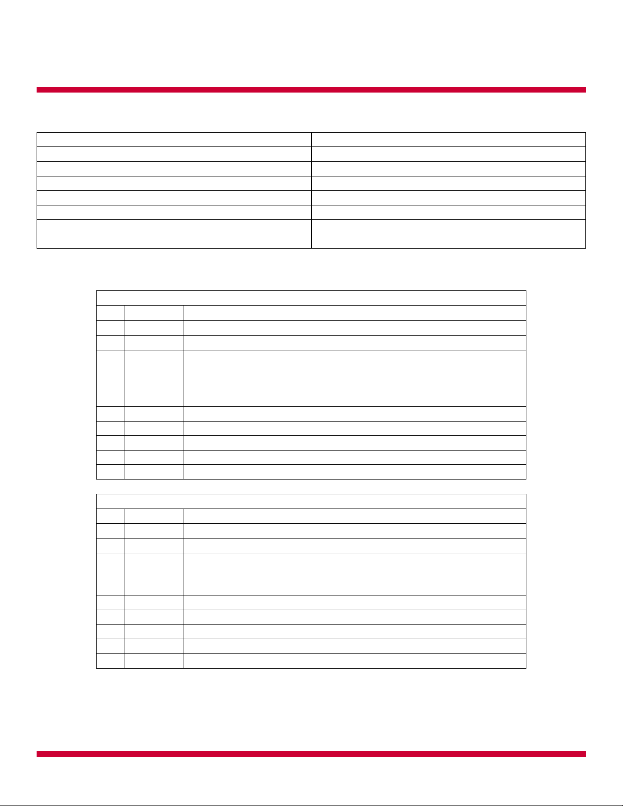
3. Pin Configurations
IS-CHPMP
Pin
Name
Function
1
V3.3
Input voltage supply between 2.7-5V.
2
V16
Output voltage preset to 16V.
3
SHTDN
Shutdown input. A logic high puts the MAX8574 into normal
operation. A logic low at SHTDN places the MAX8574 into low-
power shutdown mode. Does not have pulldown resistor for
disable.
4
GND
Ground
5
GND
5 connected to 4
6
SHTDN
6 connected to 3
7
V16
7 connected to 2
8
V3.3
8 connected to 1
IS-CHPMPHP
Pin
Name
Function
1
V3.3
Input voltage supply between 2.7-5V.
2
V16
Output voltage preset to 15V.
3
SHTDN
Shutdown input. A logic high puts the LM2735Y into normal
operation. A logic low at SHTDN places the LM2735Y into low-
power shutdown mode. Has pulldown resistor for disable.
4
GND
Ground
5
GND
5 connected to 4
6
SHTDN
6 connected to 3
7
V16
7 connected to 2
8
V3.3
8 connected to 1
Note: Incorrect installation of the connector could damage the charge pump and/or the
motherboard.

IS-CHPMP and IS-CHPMPHP Manual
7850 East Gelding Drive • Scottsdale, AZ 85260-3420
IS-CHPMP and IS-CHPMPHP Manual D.docx Page 6 of 10
Toll Free 1.877.2BUYNKK (877.228.9655) •Phone 480.991.0942 • Fax 480.998.1435
www.nkkswitches.com • Email engineering@nkkswitches.com 1120
Illustration 1, Pin Configuration in relation to
board, IS-CHPMP
Illustration 2, Pin Configuration in relation to
board IS-CHPMPHP
4. Multi-Switch Operation
OLED power consumption is based on the number of pixels on. The safe way to calculate the number of OLED
products that can be powered by one charge pump is as stated below:
Number of OLED products =Charge Pump Current Capability
AllPixelsOn Mode Max Current
It is possible to have more OLED products powered by one charge pump since under normal operation not all
the pixels are on at the same time.
If more OLED product need to be powered, then multiple charge pumps can be placed in parallel.
IS-CHPMP and IS-CHPMPHP Manual
7850 East Gelding Drive • Scottsdale, AZ 85260-3420
IS-CHPMP and IS-CHPMPHP Manual D.docx Page 7 of 10
Toll Free 1.877.2BUYNKK (877.228.9655) •Phone 480.991.0942 • Fax 480.998.1435
www.nkkswitches.com • Email engineering@nkkswitches.com 1120
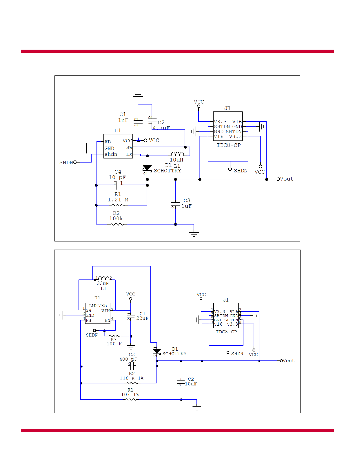
5. Schematic
Illustration 5, Schematic for IS-CHPMP
Illustration 6, Schematic for IS-CHPMPHP

IS-CHPMP and IS-CHPMPHP Manual
7850 East Gelding Drive • Scottsdale, AZ 85260-3420
IS-CHPMP and IS-CHPMPHP Manual D.docx Page 8 of 10
Toll Free 1.877.2BUYNKK (877.228.9655) •Phone 480.991.0942 • Fax 480.998.1435
www.nkkswitches.com • Email engineering@nkkswitches.com 1120
6. Build of Material
BOM for IS-CHPMP
Item
Count
Designation
Part Number
Description
Value
Package
1
1
-
P-CHPMPD
PCB/OLED CHARGE PUMP/REV D
-
-
2
1
C1
MA0805XR105K160R
CAPACITOR, 1uF, SM0805, 16V, X7R
1UF
SM0805
3
1
C2
C2012X5R0J475K
CAPACITOR, 4.7uF, SM0805, 6.3V, X5R
4.7UF
SM0805
4
1
C3
GRM219R71E105KA88D
CAPACITOR, 1uF, SM0805, 25V, X7R
1UF
SM0805
5
1
C4
GRM2165C1H4R7CD01D
CAPACITOR, 4.7pF, SM0805, 50V, COG
4.7PF
SM0805
6
1
D1
BAT42W-V-GS08
DIODE, SCHOTTKY, SOD-123, 0.200A, 30V
SOD-123
7
1
J1
PPPC042LFBN-RC
HEADER, 2x4, RECEPT, FEMALE, .100", THU,
STRAIGHT, GOLD
2x4
THR HOLE
8
1
L1
LQH32CN100K33L
INDUCTOR, 10uH, 450MA, 0.300 OHM, SMD
10UH
SMD
9
1
R1
RK73H2ATTD6044F
RESISTOR, 6.04M, SM0805, 1/8W, 1%
6.04M
SM0805
10
1
R2
RK73H2ATTD4993F
RESISTOR, 499K, SM0805, 1/8W, 1%
499K
SM0805
11
1
U1
MAX8574EUT+T
IC, SOT-23-6, LCD STEP-UP DC-DC CONVERTER,
500mA, 2.7V TO 5.5V
SOT-23-6
BOM for IS-CHPMPHP
Item
Count
Designation
Part Number
Description
Value
Package
1
1
-
P-CHPMPHP
PCB, CHARGE PUMP HIGH POWER, Rev C
-
-
2
1
C1
C2012X5R0J226M/1.25
CAPACITOR, 22uF, SM0805, 6.3V, X5R
22uF
SM0805
3
1
C2
C3216X5R1E106M
CAPACITOR, 10uF, SM1206, 25V, X5R
10uF
SM1206
4
1
C3
CC0805KRX7R9BB471
CAPACITOR, 470pF, SM0805, 50V, X7R
470pF
SM0805
5
-
C4
-
-
-
-
6
1
D1
MBR0530
DIODE, SCHOTTKY, SOD-123, 0.5A, 30V
SOD-123
7
1
J1
929975-01-36
HEADER, 2x36, .100", THU, FEMALE, STRAIGHT
Cut
2x4
THR HOLE
8
1
L1
74404054330
INDUCTOR, 33uH, 1.2A, 189 mOHM, SMD
33UH
SMD
9
1
R1
RMCF0805FT10K0
RESISTOR, 10K, SM0805, 1/8W, 1%
10K
SM0805
10
1
R2
RC0805FR-07110KL
RESISTOR, 110K, SM0805, 1/8W, 1%
110K
SM0805
11
1
U1
LM2735YMF/NOPB
VOLTAGE REGULATOR, SOT23-5, STEP-UP,
520kHz, ADJ O.P. 3-24V,2.1A
SOT23-5

IS-CHPMP and IS-CHPMPHP Manual
7850 East Gelding Drive • Scottsdale, AZ 85260-3420
IS-CHPMP and IS-CHPMPHP Manual D.docx Page 9 of 10
Toll Free 1.877.2BUYNKK (877.228.9655) •Phone 480.991.0942 • Fax 480.998.1435
www.nkkswitches.com • Email engineering@nkkswitches.com 1120
7. Board Layout
8. Board Layout for IS-CHPMP
Illustration 7, Primary side
Illustration 8, Secondary side
Note: No traces or ground plane shall be present under the inductor.
Board Layout for IS-CHPMPHP
Illustration 9, Primary side
Illustration 10, Secondary side
Note: No traces or ground plane shall be present under the inductor.
9. Dimensions

IS-CHPMP and IS-CHPMPHP Manual
7850 East Gelding Drive • Scottsdale, AZ 85260-3420
IS-CHPMP and IS-CHPMPHP Manual D.docx Page 10 of 10
Toll Free 1.877.2BUYNKK (877.228.9655) •Phone 480.991.0942 • Fax 480.998.1435
www.nkkswitches.com • Email engineering@nkkswitches.com 1120
Warranty
NKK SWITCHES LIMITED WARRANTY AND LIMITATION OF LIABILITY
The following limits our liability. Please read.
NKK Switches hereby warrants this product against any and all manufacturing defects for a period of one year from the
date of sale of this product to the original end user. NKK Switches’ liability in the event of such defect is limited to repair
or replacement of the defective products. NKK Switches disclaims any liability or warranty obligation with respect to any
product that is misused, damaged by any user, or not used in conformity with all applicable product specifications.
NKK SWITCHES HEREBY DISCLAIMS ANY WARRANTY, EXPRESS OR IMPLIED, OTHER THAN THAT CONTAINED
HEREIN. NKK SWITCHES EXPRESSLY DISCLAIMS THE WARRANTIES OF MERCHANTABILITY AND FITNESS FOR
A PARTICULAR PURPOSE, AND SHALL HAVE NO LIABILITY BASED ON OR ARISING FROM ANY CLAIM OF SUCH
WARRANTY.
NKK Switches shall have no liability to any person for any incidental, consequential, special, punitive, or other damages of
any kind whatsoever relating to any use of this product.
USE OF THIS PRODUCT IN CONNECTION WITH ANY LIFE CRITICAL APPLICATION IS NOT RECOMMENDED.
This manual suits for next models
1
Table of contents
Other NKK SWITCHES Control Unit manuals


Popular Control Unit manuals by other brands


Eaton
Eaton CEAG DLS/3PH-BUS-Module-inverse Mounting and operating instructions

Cameron
Cameron WHEATLEY 820 Series Installation, operation and maintenance manual

KIESELMANN
KIESELMANN 5093 Series Operating instruction

IDEATEC
IDEATEC POLARIS user guide

Allen-Bradley
Allen-Bradley XM-124 user manual

Honeywell
Honeywell 4219 Installation and setup guide


