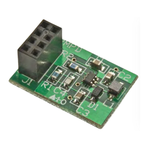
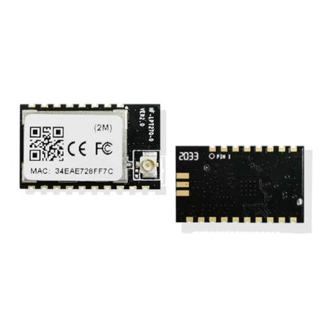
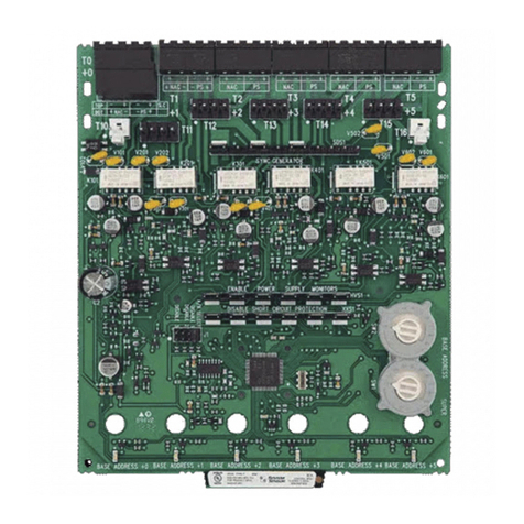
NKK SWITCHES IS-L08KP1-1S1 User manual

Universal KP Switch Modules User
Manual
Universal KP Switch Modules User Manual Rev A.docx Page 1 of 12
www.nkkswitches.com • engineering@nkkswitches.com 1221
Universal KP Switch Modules User Manual
Revision A
All Rights Reserved Worldwide
NKK Switches makes no warranty for the use of these products and assumes no responsibility for
any errors, which may appear in this document, nor does it make a commitment to update the
information contained herein.
SmartDisplay is trademark of NKK Switches.

Universal KP Switch Modules User
Manual
Universal KP Switch Modules User Manual Rev A.docx Page 2 of 12
www.nkkswitches.com • engineering@nkkswitches.com 1221
Table of Contents
Contents
1.General Features ...........................................................................................................3
2.Available Modules ........................................................................................................4
2.1.KP Modules ...............................................................................................................4
2.2.Ribbon Cables............................................................................................................5
3.Operation.......................................................................................................................5
3.1.Switch scan ................................................................................................................5
3.2.Controlling Backlight.................................................................................................5
4.Hardware.......................................................................................................................6
Warranty ..........................................................................................................................12

Universal KP Switch Modules User
Manual
Universal KP Switch Modules User Manual Rev A.docx Page 3 of 12
www.nkkswitches.com • engineering@nkkswitches.com 1221
1.General Features
The KP modules are KP switches mounted on PCB with glue logic that allows easy control and
interconnection of many modules. Six control lines can control large number of switches. The data for
backlight and reading switch statuses can be achieved with SPI or bit banging.
General features:
• Various switch matrix is possible
• Constant current control for backlights
• Serial scanning of the switches
• Various number of colors can be achieved with RGB backlight
• Brightness control
• Backlight voltage 4 to 5V
• Logic voltage of 3.3 to 5V
• 6 control signals can control large number of switches
• Modules can be daisy-chained via a 10 pins ribbon cables
• Parallel Switch scan ports available for PLC or other devices

Universal KP Switch Modules User
Manual
Universal KP Switch Modules User Manual Rev A.docx Page 4 of 12
www.nkkswitches.com • engineering@nkkswitches.com 1221
2.Available Modules
2.1. KP Modules
We currently offer two modules, and we can design different modules to customer’s requirements.
Item
Part# with Socket
and switch
Switch
Matrix
Switch Part Number
Notes
1
IS-L08KP1-1S1
2x4
KP0115ACBKG03RGBP-3FJB
Side by side stackable
2
IS-L08KP1-1S2
2x4
KP0115ANBKG03RGBP-3FJB
Side by side stackable
3
IS-L08KP1-2S1
2x4
KP0215ACBKG03RGBP-3FJB
Side by side stackable
4
IS-L08KP1-2S2
2x4
KP0215ASBKG03RGBP-3FJB
Side by side stackable
Item
Part# with Socket
and switch
Switch
Matrix
Switch Part Number
Notes
5
IS-L08KP2-1S1
1x8
KP0115ACBKG03RGBP-3FJB
Side by side stackable
6
IS-L08KP2-1S2
1x8
KP0115ANBKG03RGBP-3FJB
Side by side stackable
7
IS-L08KP2-2S1
1x8
KP0215ACBKG03RGBP-3FJB
Side by side stackable
8
IS-L08KP2-2S2
1x8
KP0215ASBKG03RGBP-3FJB
Side by side stackable

Universal KP Switch Modules User
Manual
Universal KP Switch Modules User Manual Rev A.docx Page 5 of 12
www.nkkswitches.com • engineering@nkkswitches.com 1221
2.2. Ribbon Cables
These cables are used for connecting KP Modules.
Item
Part#
Length
Description
1
IS-RC10-12
12”
RIBBON CABLE, 10 CONDUCTORS, 28AWG, .050" PITCH
2
IS-RC10-24
24”
RIBBON CABLE, 10 CONDUCTORS, 28AWG, .050" PITCH
3
IS-RC10-36
36”
RIBBON CABLE, 10 CONDUCTORS, 28AWG, .050" PITCH
Custom length cable can be made to order.
3.Operation
3.1. Switch scan
Switch scan is initiated by setting LPSWRD low then high. The switch statuses are transferred to the
shift registers when LPSWRD is low. By toggling the clock (CLK) line the switch statuses are read
from SWRDout line. The first bit received is the last switch (switch#8) of the first module. Reading all
the switches require as many clock as the number of switches. The switch being pressed can be
identified by the associated bit = 0.
The switch scan is also available for PLC or other devices without interfering with the serial scan.
Through-hole pads with 0.1”x0.1” are provided for scanning. The number of pads equal the number of
switches.
3.2. Controlling Backlight
Backlight data are shifted via clock (CLK) and DATAin. Each 8 KP switches require 24 bits of data for
backlight. First bit shifted is FOR BLUE COLOR Switch #1, the 8th bit is for blue switch#8, 9th bit is
for green switch#1, 17th bit is for red switch #1. When the associated bit = 1 then the backlight is on.
For multiple board the first set of 24 bit is for the last board and the last set is for the first board.

Universal KP Switch Modules User
Manual
Universal KP Switch Modules User Manual Rev A.docx Page 6 of 12
www.nkkswitches.com • engineering@nkkswitches.com 1221
4.Hardware
WARNING: These products are ESD sensitive. The ESD handling procedure must be followed.
L08KP1 Dimensions in inches:
Secondary side, looking down at switches

Universal KP Switch Modules User
Manual
Universal KP Switch Modules User Manual Rev A.docx Page 8 of 12
www.nkkswitches.com • engineering@nkkswitches.com 1221
Connectors:
J1 Input port: 5x2 male header 0.1”x0.1” spacing.
This connector connects to the controller or J2 of the previous module board in the daisy chain.
Pin
Function
1
DATAin Data for backlights from controller or previous module
2
GND
3
CLK Clock for LED backlights and switch scan
4
GND
5
SWRDout Switch read data to previous board or controller
6
VDD
7
LPSWRD Latch pulse for switch status to shift register
8
VLED Voltage for backlight. 4 to 5V
9
LPLED Latch pulse for shifted data to the driver
10
ENLED Enable/Disable LED driver
J2 Output port: 5x2 male header 0.1”x0.1” spacing.
This connector connects to J1 of the next logic board in the daisy chain.
Pin
Function
1
DATAout Data for next module backlight
2
GND
3
CLK Clock for LED backlights and switch scan
4
GND
5
SWRDin Switch read data from next module
6
VDD
7
LPSWRD Latch pulse for switch status to shift register
8
VLED Voltage for backlight. 4 to 5V
9
LPLED Latch pulse for shifted data to the driver
10
ENLED Enable/Disable LED driver
Note: Pin 1 of the connector must be matched with pin 1 of the
preceding connector.
L08KP1
L08KP2

Universal KP Switch Modules User
Manual
Universal KP Switch Modules User Manual Rev A.docx Page 12 of 12
www.nkkswitches.com • engineering@nkkswitches.com 1221
Warranty
NKK SWITCHES LIMITED WARRANTY AND LIMITATION OF LIABILITY
The following limits our liability. Please read.
NKK Switches hereby warrants this product against any and all manufacturing defects for a period of
one year from the date of sale of this product to the original end user. NKK Switches’ liability in the
event of such defect is limited to repair or replacement of the defective products. NKK Switches
disclaims any liability or warranty obligation with respect to any product that is misused, damaged by
any user, or not used in conformity with all applicable product specifications.
NKK SWITCHES HEREBY DISCLAIMS ANY WARRANTY, EXPRESS OR IMPLIED, OTHER THAN
THAT CONTAINED HEREIN. NKK SWITCHES EXPRESSLY DISCLAIMS THE WARRANTIES OF
MERCHANTABILITY AND FITNESS FOR A PARTICULAR PURPOSE, AND SHALL HAVE NO
LIABILITY BASED ON OR ARISING FROM ANY CLAIM OF SUCH WARRANTY.
NKK Switches shall have no liability to any person for any incidental, consequential, special, punitive,
or other damages of any kind whatsoever relating to any use of this product.
USE OF THIS PRODUCT IN CONNECTION WITH ANY LIFE CRITICAL APPLICATION IS NOT
RECOMMENDED.
This manual suits for next models
3
Table of contents
Other NKK SWITCHES Control Unit manuals
Popular Control Unit manuals by other brands
Burkert
Burkert 2103 Series operating instructions
Festo
Festo MSE6-C2M Instructions & Operating
Omron
Omron C200HW-SRM21-V1 - 08-2007 Operation manual
System Sensor
System Sensor SpectrAlert MDL Installation and maintenance instructions
Spirax Sarco
Spirax Sarco TD3-3 Installation and maintenance instructions

Moeller
Moeller S40-AM-TD manual


