NKT Photonics Koheras BOOSTIK HP User manual
Item: 800-636-01
Customer Revision: 1.0
NKTP Revision: 1-0
Release Date: 12-2022
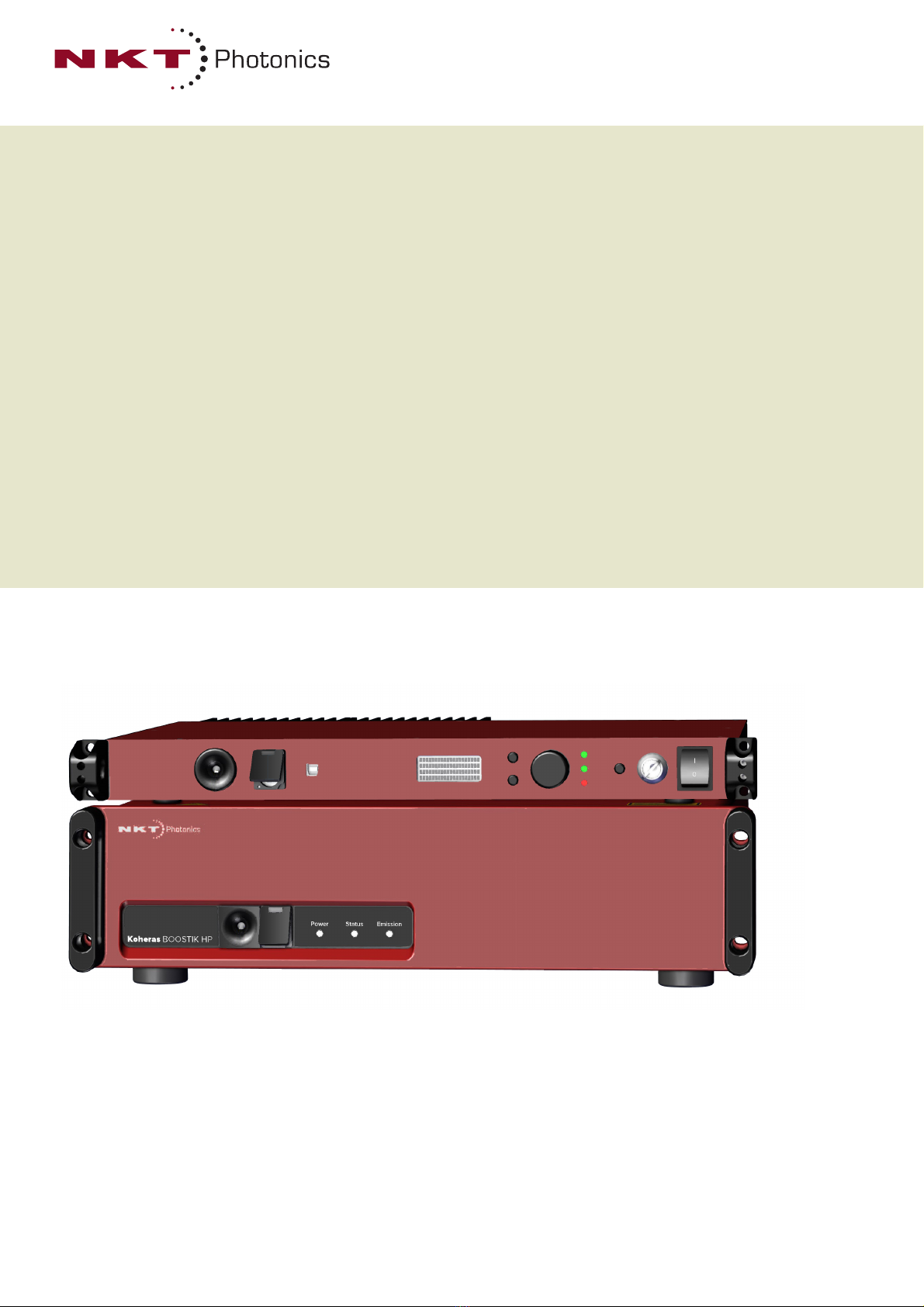
Koheras BOOSTIK HP
PRODUCT GUIDE
Continuous Wave Fiber Amplifier

PRODUCT GUIDE
This guide includes the following NKT Photonics laser amplifiers:
Koheras BOOSTIK HP – E15 seed
Continuous Wave Fiber Amplifier
Koheras BOOSTIK HP – C15 seed
Continuous Wave Fiber Amplifier
Koheras BOOSTIK HP – X15 seed
Continuous Wave Fiber Amplifier
Koheras BOOSTIK HP – Y10 seed
Continuous Wave Fiber Amplifier
W-10456
3
GUIDE OVERVIEW
This product guide is intended to provide functional, operational and installation
information for the Koheras BOOSTIK HP laser amplifiers.
Warning: Do not operate the laser amplifier before first reading and understand-
ing all warnings, cautions and handling information stated within the document:
Koheras BOOSTIK HP Safety, Handling and Regulatory Information
Note: The paper copy of this document is included with your laser; however, it
can also be downloaded from:
https://www.nktphotonics.com/product-manuals-and-documentation/
Warning: Use of controls or adjustments or performance of procedures other
than those specified herein may result in hazardous radiation exposure.
Terminology This guide refers to the Koheras BOOSTIK HP as the BOOSTIK HP, “the amplifier”
or “the laser amplifier”. In specific cases where a distinction is required, this guide
will use the actual model names. The BOOSTIK HP product line is built as a com-
plete system including a separate seed laser source. Seed laser models can be
either Koheras ADJUSTIK or a Koheras ACOUSTIK with a BASIK module. The
manual may refer to them also as the “seed laser”, “laser source”, or simply
“seed”. The guide also refers to both the BOOSTIK HP amplifier and seed laser
together as a BOOSTIK HP system or simply “the system”.
Target audience This guide is for technical personnel involved in the selection, planning and
deployment of lasers in laboratory and industrial settings. The guide assumes a
reasonable knowledge level of lasers, photonic principles and electrical interface
connectivity.
Chapters inside This guide includes the following chapters:
• Chapter I “BOOSTIK HP Description” — Describes the laser amplifier
including its general operational principles, management and interfaces.
• Chapter 2 “Mechanical Installation” — Provides information on installing the
laser amplifier including rack and surface mounting and environmental
conditions required.
• Chapter 3 “Connecting the BOOSTIK HP” — This chapter includes
information on connecting the safety interlock, AC power, and making optical
connections.
• Chapter 4 “ADJUSTIK Front Panel Operation” — Provides information and
procedures on how to operate the laser amplifier using the front panel of the
ADJUSTIK seed laser.

Guide Overview 4
• Chapter 5 “CONTROL Interface” — This chapter describes the CONTROL
software interface including descriptions of all panels and menu items.
• Appendices — The multiple appendices include amplifier specifications,
servicing and support contact details, a list of errors, and CONTROL software
installation instructions.
Reference
documents
A BOOSTIK HP system consists of the Koheras BOOSTIK HP amplifier and either
a Koheras ADJUSTIK seed laser or a Koheras ACOUSTIK rack fitted with Koheras
BASIK seed lasers. For information on operating the seed lasers refer to the
following NKT Photonics documents:
Koheras ADJUSTIK
• Koheras ADJUSTIK Product Guide
• Koheras ADJUSTIK Safety, Handling and Regulatory Information
Koheras ACOUSTIK
• Koheras ACOUSTIK Product Guide
• Koheras ACOUSTIK Safety, Handling and Regulatory Information
Added information
and safety notices
Lasers are highly dangerous devices that can cause serious injury and property
damage. This guide uses the following symbols to either highlight important
safety information or provide further information in relation to a specific topic.
Note: Highlights additional information related to the associated topic and/or
provides links or the name of the NKT Photonic guides describing the additional
information.
Caution: Alerts you to a potential hazard that could cause loss of data or damage
the system or equipment.
Warning: The laser safety warning alerts you to potential serious injury that may
be caused when using the laser amplifier.
Revision This section records the document revision details.
Date Revision Changes
2022-12 1.0 First release

5
CONTENTS
Guide Overview ............................................................................................... 3
TABLES ............................................................................................... 9
FIGURES ........................................................................................... 11
PROCEDURES 13
1 BOOSTIK HP Description ............................................................................. 15
Optical output ..................................................................................... 15
Amplifier characteristics ..................................................................... 15
Integrated systems ............................................................................. 15
Amplifier features ............................................................................... 16
Front and rear panels .............................................................................17
Front panel ......................................................................................... 17
Rear panel ......................................................................................... 18
Optical outputs ........................................................................................20
Collimator ........................................................................................... 21
Beam diameter ................................................................................... 22
Factory test report .............................................................................. 22
Output polarization ............................................................................. 22
Polarization ring ................................................................................. 22
Safety .....................................................................................................23
Managing the amplifier ...........................................................................24
Operations interface ........................................................................... 24
Chassis labels ........................................................................................24
Label descriptions .............................................................................. 25
Label locations ................................................................................... 25
2 Mechanical Installation .................................................................................. 27
Installation ..............................................................................................27
Table installation ................................................................................ 27
Rack installation ................................................................................. 28

6
Location and environment ................................................................. 28
AC mains ........................................................................................... 29
Airflow .....................................................................................................29
3 Connecting the BOOSTIK HP ....................................................................... 31
Connecting the safety interlock ..............................................................31
Interlock connection ........................................................................... 31
Connecting a door interlock switch .................................................... 33
External bus cable and bus defeater ......................................................33
Setting the External bus address ....................................................... 34
Connecting power ................................................................................... 36
Connecting the optical input from a seed laser ......................................37
Seed to amplifier optical connection .................................................. 37
Before making the optical connection ................................................ 37
Connecting a PC with CONTROL software ............................................37
CONTROL software ........................................................................... 37
Installing CONTROL software ........................................................... 37
Connecting the BOOSTIK HP system to a CONTROL PC ....................37
Ethernet connection ........................................................................... 38
4 ADJUSTIK Front Panel Operation ................................................................ 41
Front Panel Operation (ADJUSTIK) .......................................................41
Enable emission – front panel controls .............................................. 42
5 CONTROL Interface ..................................................................................... 45
CONTROL overview ...............................................................................45
Relocating panels .............................................................................. 46
Toggling the panels visible ................................................................ 47
Connecting to the BOOSTIK HP system ........................................... 47
Status Panel ........................................................................................... 48
Status Indicators ................................................................................ 48
System Info ........................................................................................ 49
Measurements ................................................................................... 49
WL button .......................................................................................... 49
Emission button ................................................................................. 49

7
Control settings .......................................................................................50
Wavelength modulation ..................................................................... 50
Power/Current mode .......................................................................... 53
Ethernet ............................................................................................. 54
Watchdog ........................................................................................... 54
Clock .................................................................................................. 55
View ................................................................................................... 55
CONTROL menu ....................................................................................57
Key Updater tool ................................................................................ 57
Log Downloader ................................................................................. 58
Extensions overview .......................................................................... 60
Control panel ..........................................................................................61
Power mode ....................................................................................... 61
Current mode ..................................................................................... 61
Application Log panel .............................................................................62
Device Monitor ........................................................................................63
A Specifications ................................................................................................ 65
B Service and support Information ................................................................... 67
Servicing the amplifier ............................................................................67
Opening the amplifier chassis ............................................................ 67
WARRANTY VOID IF REMOVED Label ........................................... 67
Support contact details ...........................................................................68
Support website ................................................................................. 68
Shipping address ............................................................................... 68
C Errors ............................................................................................................ 69
Errors ...................................................................................................... 69
D Control Software ........................................................................................... 71
Installing CONTROL ...............................................................................71

8

9
TABLES
Table 1: BOOSTIK HP models......................................................................... 16
Table 2: Front panel LED conditions ................................................................ 18
Table 3: BOOSTIK HP Optical outputs............................................................. 21
Table 4: Module labels ..................................................................................... 25
Table 5: BOOSTIK HP operating and storage environment............................. 28
Table 6: Power specifications........................................................................... 36
Table 7: Device Monitor parameters ................................................................ 63
Table 8: Optical specifications.......................................................................... 65
Table 9: Operating and storage environment .................................................. 66
Table 10: Electrical specifications .................................................................... 66
Table 11: Mechanical dimensions ................................................................... 66
Table 12: System errors .................................................................................. 69

10

11
FIGURES
Figure 1: Rack mounted BOOSTIK HP with ADJUSTIK seed laser ................ 15
Figure 2: Rack mounted BOOSTIK HP with ACOUSTIK seed laser(s) ........... 16
Figure 3: BOOSTIK HP front panel layout ....................................................... 17
Figure 4: BOOSTIK HP rear panel layout ........................................................ 19
Figure 5: ADJUSTIK BOOSTIK HP optical outputs and inputs ....................... 21
Figure 6: BOOSTIK HP collimator ................................................................... 22
Figure 7: Rear panel label locations ................................................................ 25
Figure 8: Top panel label locations .................................................................. 26
Figure 9: Bottom panel label locations ............................................................ 26
Figure 10: Table or shelf installation ................................................................ 27
Figure 11: Rack installation ............................................................................. 28
Figure 12: Koheras BOOSTIK HP ventilation clearance ................................. 29
Figure 13: Interlock connected to a door switch - Laser ON ........................... 32
Figure 14: Interlock connected to a door switch - Laser SHUTDOWN ............ 32
Figure 15: External bus cable and bus defeater .............................................. 34
Figure 16: External bus address – multiple BOOSTIK HP amplifiers .............. 35
Figure 17: Connecting AC mains ..................................................................... 36
Figure 18: ADJUSTIK front panel layout ......................................................... 42
Figure 19: CONTROL navigation .................................................................... 45
Figure 20: Dragging panels to a new location in the main window .................. 46
Figure 21: Dragging panels outside the main window ..................................... 46
Figure 22: Toggling panel visibility .................................................................. 47
Figure 23: Quick connect ................................................................................. 47
Figure 24: Status Panel ................................................................................... 48
Figure 25: CONTROL settings ........................................................................ 50
Figure 26: Wavelength modulation - internal source ....................................... 51
Figure 27: Wavelength modulation - external source ...................................... 51
Figure 28: Internal generator waveform selection – type ................................ 51

12
Figure 29: Turning on wavelength modulation ................................................ 53
Figure 30: Setting the power/current operating mode ..................................... 53
Figure 31: Ethernet settings ............................................................................ 54
Figure 32: Watchdog settings .......................................................................... 55
Figure 33: Setting the clock ............................................................................. 55
Figure 34: View settings .................................................................................. 56
Figure 35: Menu items ..................................................................................... 57
Figure 36: Extensions Overview ...................................................................... 60
Figure 37: Operating mode set to Power ......................................................... 61
Figure 38: Operating mode set to Current ....................................................... 62
Figure 39: Application Log window .................................................................. 62
Figure 40: Mechanical dimensions .................................................................. 66
Figure 41: Warranty seal ................................................................................. 67
white

13
PROCEDURES
Procedure 1: Clearing the interlock alarm (permit emission)........................... 31
Procedure 2: Connecting a PC to the system using a USB cable................... 38
Procedure 3: Connecting a PC to the system using Ethernet ......................... 39
Procedure 4: Enable emission with ADJUSTIK front panel controls ............... 42
Procedure 5: Relocating panels ...................................................................... 46
Procedure 6: Using the Key Updater tool........................................................ 58
Procedure 7: Using the Log Downloader......................................................... 59
Procedure 8: Installing CONTROL ................................................................... 71

14
15
1 BOOSTIK HP Description
The Koheras BOOSTIK HP system is a Continuous Wave (CW) laser and amplifier
system. The system produces and amplifies infrared laser light that is ultra-bright and
near-diffraction-limited. The amplified light is then delivered through an armored fiber
to collimating optics for emission output.
The amplifier contains reliable, high-brightness diode lasers that pump a double-clad,
ErYb-doped or Yb-doped optical fiber. Microprocessor controlled electronics power
the diode lasers and control the fiber amplifier operation. A heat sink and fan provide
the necessary cooling for reliable operation. All components of the system are
housed in chassis that are both benchtop and rack mountable and include front panel
controls.
Optical output
A BOOSTIK HP emits fundamentally transverse mode (TEM00) continuous wave
radiation in the 1064nm or 1550nm range. Optical power is continuously adjustable
from 3 to 15 W.
Amplifier
characteristics
With the amplifier used in a Koheras BOOSTIK HP system, the laser’s optical output is
defined by an ultra-narrow line width in the Hertz range and exceptionally low
frequency and intensity noise. These characteristics make the laser suitable for
applications such as quantum optics, computing and other phenomena like optical
trapping, optical lattice, Bose-Einstein condensate, atom interferometry, and
squeezing.
Note:
Other applications for a BOOSTIK HP system include using it as a linear optics
pump source in conjunction with second harmonic and differential frequency genera-
tion, optical parameter oscillators, and laser-based metrology.
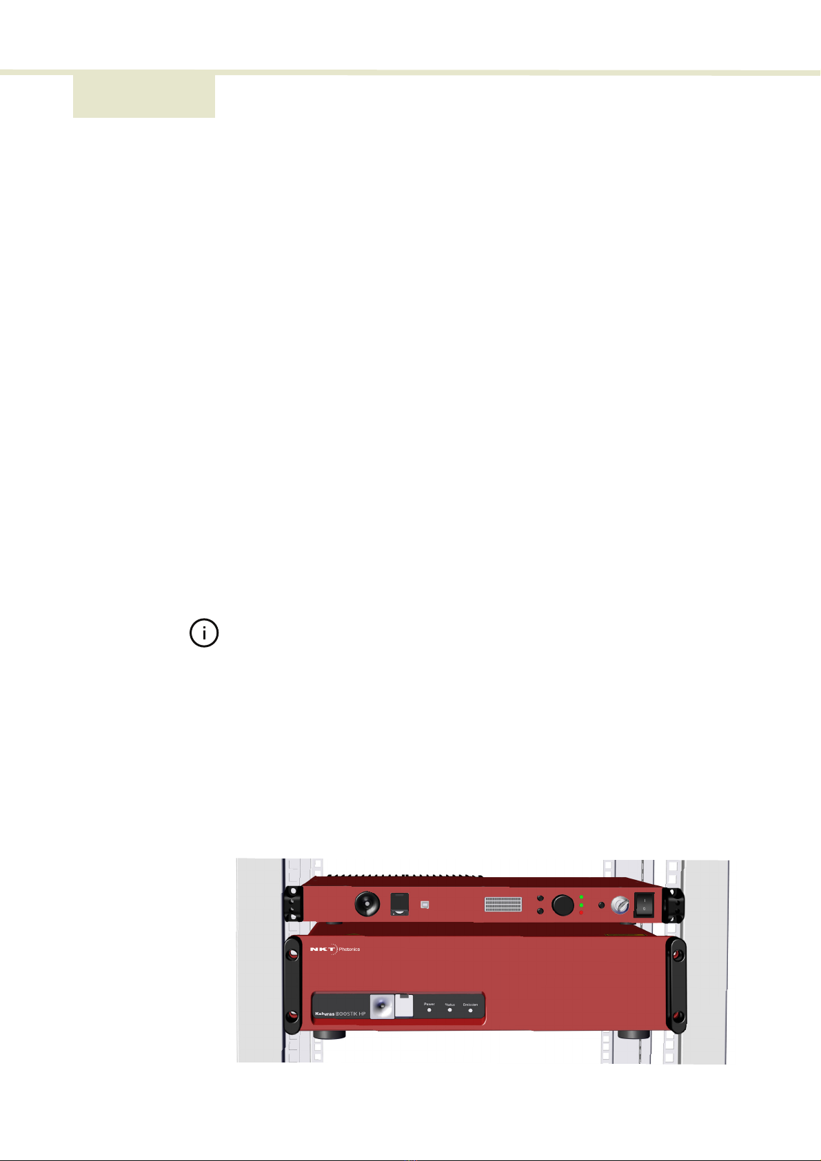
Integrated systems BOOSTIK HP system with Koheras ADJUSTIK
When integrated with a Koheras ADJUSTIK, the BOOSTIK HP system operates in a
master/slave configuration. A Koheras BOOSTIK amplifier (slave) is paired with a
Koheras ADJUSTIK laser (master). The Koheras ADJUSTIK functions as a seed laser
source, and when combined with the amplifier, the master device (the ADJUSTIK)
manages all the controls of the slave device (the BOOSTIK HP amplifier).
Figure 1 Rack mounted BOOSTIK HP with ADJUSTIK seed laser
Seed laser
BOOSTIK HP amplifier
BOOSTIK HP Description
BOOSTIK HP Description 16
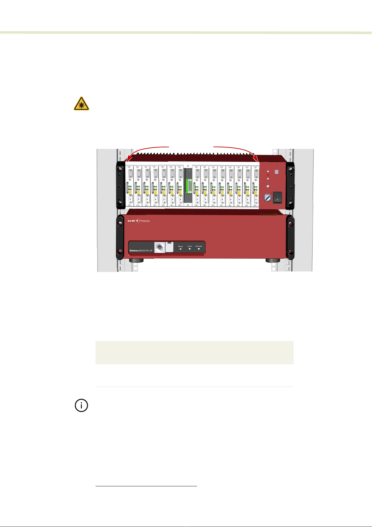
BOOSTIK HP system with Koheras ACOUSTIK
When the amplifier is integrated with a Koheras ACOUSTIK multi-wavelength system
it can be seeded by one of a range of ultra-low phase noise single-frequency laser
modules
1
: This gives high flexibility and freedom to select specific wavelengths and
power levels required for multiple discrete applications.
Warning: You must safely terminate the optical output of seed laser modules in-
serted in an ACOUSTIK rack which are not connected to a BOOSTIK HP amplifi-
er.
Figure 2 Rack mounted BOOSTIK HP with ACOUSTIK seed laser(s)
Wavelengths and power
BOOSTIK HP systems are specified by two models based on the Koheras seed type
used for its input; either E15 or X15 and Y10.
Table 1
below lists the models and their
associated specifications.
Table 1 BOOSTIK HP models
Note:
Documents describing other devices in a BOOSTIK HP system are listed under
“Reference documents” on page 4
.
Amplifier features
The BOOSTIK HP system includes the following key features:
• Interlock and keyswitch – shuts the laser off upon unauthorized or accidental
access and prevents unauthorized operation.
1. Specifically, Koheras BASIK seed laser modules.
Model
Standard
wavelengths
Custom
wavelengths
Standard
output
power
E15 or X15 laser seed 1545-1565 nm 1535-1575 nm 10 or 15 W
Y10 laser seed 1050-1075 nm 1050-1090 nm 10 or 15 W
Seed laser modules
BOOSTIK HP amplifier
2

17 BOOSTIK HP Description
Front and rear panels
• Back reflection detection and shutdown – upon detection of back reflection,
the BOOSTIK HP system automatically shuts down to help prevent damage
to internal components and potential performance degradation.
• Front panel controls and display – operation menu display with selection dial
and navigation buttons (ADJUSTIK systems only).
• Enable/Disable button with emission LED indicator(s)
• Remote PC control – Command Line Interface over a serial USB connection.
• FC/APC connectors for optical input and monitor output.
• Collimator at the end of an armored fiber for primary optical output.
• 19 inch rack mounting flanges with chassis handles
Front and rear panels
Front panel Figure 3
shows the front panel of a BOOSTIK HP amplifier chassis
Figure 3 BOOSTIK HP front panel layout
Optical output
Optical output is Class 4 emission delivered through an output fiber to a collimator.
The collimator is the amplifier’s primary optical output.
Optical input
Optical input is received from a seed laser through an FC/APC connector.
The input to a BOOSTIK HP amplifier is designed to receive light from a CW seed
laser. The output of the seed can be frequency modulated within a range as specified
by the output from the Koheras BASIK modules listed in
Table 1
.
1 Optical output - to collimator 4 Status LED
2 Optical input - FC/APC connector 5 Emission LED
3 Power LED 6 Rack mounting flanges with handles
16
2345
6

Front and rear panels
BOOSTIK HP Description 18
Caution: Only connect a seed laser source as specified in Table 1. Amplitude
modulated or pulsed input can result in extensive damage to the BOOSTIK
HP amplifier.
Caution: Do not connect a seed laser source with a wavelength beyond
the optical input wavelength range specified for your amplifier. Doing so may burn
the system components.
Caution: Do not connect a seed laser source with a power level that exceeds 50
mW. Doing so may burn the system components.
Power LED
This LED indicates when power is applied to the BOOSTIK HP amplifier – see
Table 2
.
Status LED
This LED indicates the status of the BOOSTIK HP amplifier – see
Table 2
.
Emission LED
The emission LED indicates if emission is enabled – see
Table 2
.
Table 2 Front panel LED conditions
Warning: When the emission LED is flashing or ON, dangerous laser emissions
are present. Take all proper safety precautions necessary. The Koheras BOOS-
TIK HP Safety, Handling and Regulatory Information document provides multiple
safety information that should be adhered to along with applicable regional safe-
ty regulations.
Rack mounting handles
Use the handles as grips when transporting the amplifier or mounting it in a 19 inch
equipment rack.
Rear panel Figure 4
shows the rear panel which includes multiple connectors, a ventilation
outlet, a switch controlled AC power connection, an address selector for the
communication bus, and a holder for the output collimator. Connectors include ports
for monitor, control signals, interlock, and connected accessories.
LED
Condition Description
Power ON AC mains connected and rear panel power switch set ON.
OFF AC mains disconnected or rear panel power switch set OFF.
Status ON Emission is enabled or the amplifier is capable of enabling
emission.
Blinking The interlock is open or interrupted by an error.
Emission ON Emission enabled (laser amplifier output turned ON)
19 BOOSTIK HP Description
Front and rear panels
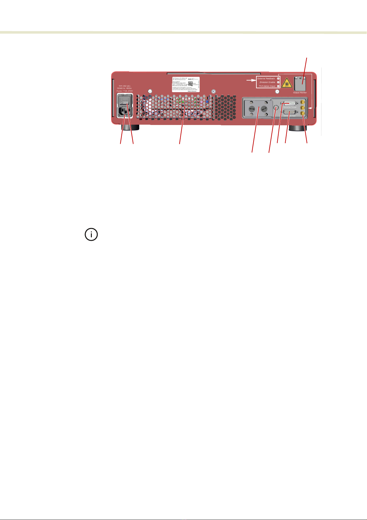
Figure 4 BOOSTIK HP rear panel layout
Note:
The pin assignments of the Interlock are described in:
“Connecting the BOOSTIK HP” on page 31
.
AC mains input
AC inlet - standard IEC C-14 mains inlet connector - see
“Connecting power” on
page 36
.
AC mains ON/OFF switch
Press ( I ) to turn on the amplifier power and ( 0 ) to turn it off.
Cooling fan exhaust vent
To maintain the laser amplifier’s operating temperature, cool air is drawn into the
chassis from the bottom panel vent and system heated air is subsequently expelled
from the exhaust vent on the rear panel. During operation, ensure to keep the areas
in front of both vents clear of any obstructions that could block the free flow of air.
Collimator holder
A receptacle that secures the collimator in place when transporting or storing the
amplifier. DO NOT operate the amplifier when the collimator is placed in the holder.
External bus address selector
This is a rotary switch which sets an offset to the External bus communication
address. You can use the switch to set a bus address offset from 0x0 to 0xF. Devices
on the External bus must have a unique bus address. Without setting an offset, the
main module address for a standard BOOSTIK HP is 0x40 – see
“Setting the
External bus address” on page 34
.
1 AC mains power input – C14 6 External bus through (out) – DB-15
2 AC mains ON/OFF switch 7 External bus input – DB-15
3 Cooling fan exhaust vent 8 SMA connectorsi
i. From top to bottom: External feedback, Emission enable, Modulation input
4 Collimator holder 9 Optical monitor output – FC/APC
5 External bus address selector
5
SMA connector
legend
37
1268
54
9

Optical outputs
BOOSTIK HP Description 20
External bus through
When operating without smart accessories, connect the included bus defeater to this
port. The bus defeater loops back the interlock, see –
“External bus cable and bus
defeater” on page 33
. Smart accessories can connect to the external bus for
communications, power and interlock signals. In the future, should accessories
become available, you can connect them to this port.
External bus input
Connect this to the seed laser of your BOOSTIK HP system; either an ADJUSTIK or
ACOUSTIK. The bus carries communication over RS-485 protocol and importantly,
the interlock signal from the seed laser.
MWarning: DO NOT BYPASS the interlock on
system’s seed laser
by jumping the
pins on the interlock connector. Laser regulations require that the interlock is
connected to a safety door switch. When the door switch circuit is open, the laser
is immediately disabled.
Note:
The Koheras BOOSTIK HP system has built-in safety relay and interlock fea-
tures to help ensure laser radiation is emitted only when it is expected and only when
predetermined conditions are met.
The remote interlock and remote stop features render the system inoperable when a
predefined condition occurs, such as the opening of a door. The internal safety relay
is analogous to a beam shutter. It interrupts drive current to the diode pump lasers,
and it is open each time the system is turned on. This means it will be impossible to
apply current to the diode pump lasers until you specifically take action to close the
circuit and reset the front panel keyswitch on the seed laser – see
“Connecting the
safety interlock” on page 31
.
External Feedback
Reserved for future use.
Emission ON/OFF
Reserved for future use.
Modulation Input
Reserved for future use.
Monitor output
FC/APC connector – emitting approximately 0.05% to 0.2% of the amplifier’s
main optical output power. Emission from the monitor output is classified as
CLASS 3B.
Optical outputs
The optical outputs for
BOOSTIK HP systems are listed in Table 3. A diagram of
optical outputs and inputs is shown in Figure 5.
This manual suits for next models
4
Table of contents
Other NKT Photonics Amplifier manuals


Popular Amplifier manuals by other brands


Pioneer
Pioneer A-7 Service manual

Rockford Fosgate
Rockford Fosgate Mono Amplifier Installation & operation manual

Hubbell
Hubbell GAI-TRONICS SP2 manual

ORTEC
ORTEC 575A Operating and service manual

QRO Technologies
QRO Technologies HF-3KDX instruction manual

Sony
Sony TA-AV571 - Integrated A/v Amplifier operating instructions


