NKT Photonics Koheras BOOSTIK LC User manual
Item 800-631-01
Koheras BOOSTIK LC
PRODUCT GUIDE
Narrow linewidth laser amplifier

PRODUCT GUIDE
This guide includes the following NKT Photonics Lasers:
Koheras BOOSTIK LC 2W 1550 nm
2W narrow linewidrh line card amplifier housed in a line card form factor
Koheras BOOSTIK LC 200 mW 1550 nm
200 mW narrow linewidrh line card amplifier housed in a line card form factor
Koheras BOOSTIK LC 200 mW 1064 nm
200 mW narrow linewidrh line card amplifier housed in a line card form factor
Koheras BOOSTIK LC Product Description Revision 1.1 10-2021 W-10456
3
GUIDE OVERVIEW
This product guide is intended to provide functional, operational and installation
information for Koheras BOOSTIK LC laser amplifiers.
Warning: Do not operate the laser before first reading and understanding all warn-
ings, cautions and handling information stated within the document:
Koheras BOOSTIK LC-series Laser Safety, Handling and Regulatory Information
Warning: Use of controls or adjustments or performance of procedures other than
those specified herein may result in hazardous radiation exposure.
Documentation A USB memory stick is included. It contains the soft copy documentation for this
laser.
Terminology The guide may refer to both the Koheras BOOSTIK LC as the laser amplifier or just
simply module. The Koheras BOOSTIK LC is a module designed to be fitted to and as
part of a complete laser system.
Target Audience This guide is for technical personnel involved in the selection, planning and
deployment of lasers in laboratory and industrial settings. The guide assumes a
reasonable knowledge level of lasers, photonic principles and electrical interface
connectivity.
Chapters Inside This guide includes the following chapters:
• Chapter I “Description” — Describes the Koheras BOOSTIK LC laser amplifier
module including its general operational description and features, interfaces.
• Chapter 2 “Installation” — Includes information and procedures on how to
correctly install the module. Procedures within this chapter focus on providing
adequate temperature regulation.
• Chapter 3 “CONTROL GUI” — Introduces and describes how to use the software
control interface software to manage the module.
• Chapter 4 “SDK Registers and Tabs” — An introduction to the registers and tabs
of the Generic User Interface included with the NKT Photonics Software
Development Kit.
• Appendices — The guide includes multiple appendices including specifications,
support contact details, connector pin assignments, error codes and a control
software installation procedure.

4
Added information
and Safety Notices
Lasers are highly dangerous devices that can cause serious injury and property
damage. This guide use the following symbols to either highlight important safety
information or provide further information in relation to a specific topic.
Note: Highlights additional information related to the associated topic and/or pro-
vides links or the name of the NKTP guides describing the additional information.
Caution: Alerts you to a potential hazard that could cause loss of data, or damage the
system or equipment.
Warning: The laser safety warning alerts you to potential serious injury that may be
caused when using the laser.
Revision This section records the document revision history.
Release date Version and changes
2021-September 1st revision
2021-October Revision 1.1
Added the following:
•“CONTROL settings” on page 33 - added
Power/Current mode setting item in the
table.
•“Power/current mode” on page 34
•“Current mode” on page 41
•Error codes 65 and 65 to Table 14 on page 59
Updated the following:
•Figure 38 on page 50 - added Bit 8 - Input
power low.

5
CONTENTS
Guide Overview ............................................................................................... 3
Documentation ..................................................................................... 3
Terminology ......................................................................................... 3
TABLES ............................................................................................... 9
FIGURES ........................................................................................... 11
PROCEDURES .................................................................................. 13
1 Description .................................................................................................... 15
Variants .............................................................................................. 16
Front and rear panels .............................................................................16
Front panel ......................................................................................... 16
Rear panel ......................................................................................... 18
CONTROL GUI ................................................................................. 19
Generic UI and NKT Photonics SDK ................................................. 19
Enabling emission .............................................................................. 19
BOOSTIK LC labels ........................................................................... 21
2 Installation ..................................................................................................... 23
Safety .....................................................................................................23
Passive cooling .......................................................................................23
Rear panel ......................................................................................... 23
Left side panel surface ....................................................................... 24
Custom mounting ...................................................................................24
Custom installation rules .................................................................... 25
Interlock .................................................................................................. 25
Fiber tip cleaning ....................................................................................26
Signs of damage ................................................................................ 26
Damaged facet ................................................................................... 27
Polishing ................................................................................................. 27
3 CONTROL GUI ............................................................................................. 29

6
CONTROL GUI overview .......................................................................29
Relocating panels .............................................................................. 30
Connecting to the laser ...................................................................... 31
Device Selector .................................................................................. 31
Status panel ............................................................................................ 32
Status indicators ................................................................................ 32
Error messages ................................................................................. 33
System info ........................................................................................ 33
Measurements ................................................................................... 33
Emission button ................................................................................. 33
CONTROL settings ............................................................................ 33
CONTROL menu .................................................................................... 35
Key Updater tool ................................................................................ 36
Log downloader ................................................................................. 36
Extensions overview .......................................................................... 38
Device monitor ................................................................................... 39
Application log ................................................................................... 40
Power mode ....................................................................................... 41
Current mode ..................................................................................... 41
Module overview ..................................................................................... 42
Toggling and sorting the overview fields ............................................ 43
4 SDK Registers and Tabs .............................................................................. 45
SDK installer ...................................................................................... 45
Read/write registers ................................................................................45
Output power setpoint ........................................................................ 46
Emission ............................................................................................ 46
Setup bits ........................................................................................... 47
Stage one input monitor ..................................................................... 48
Pump temperature ............................................................................. 48
Heat sink temperature ....................................................................... 49
Errors and status indicators ....................................................................50

7
Status indicators ................................................................................ 50
Errors ................................................................................................. 50
Graphing .................................................................................................50
A Specifications ................................................................................................ 53
B Service and Support Information ................................................................... 55
Servicing the laser ..................................................................................55
Opening the module ........................................................................... 55
WARRANTY VOID IF REMOVED label ............................................. 55
Support website ................................................................................. 56
C Electrical interface pinout .............................................................................. 57
D Fault troubleshooting ..................................................................................... 59
Contact support .................................................................................. 59
E CONTROL installation ................................................................................... 61

8

9
TABLES
Table 1: BOOSTIK LC variants and their characteristics ................................. 16
Table 2: Status LEDs........................................................................................ 20
Table 3: BOOSTIK LC Chassis labels ............................................................. 21
Table 4: CONTROL panels and menu ............................................................. 29
Table 5: Device Monitor parameters ................................................................ 39
Table 6: Module overview fields ....................................................................... 43
Table 7: Generic user interface registers ......................................................... 45
Table 8: Optical specifications ......................................................................... 53
Table 9: Power consumption............................................................................ 53
Table 10: Mechanical dimensions ................................................................... 53
Table 11: Operating and storage environment ................................................ 53
Table 12: Safety and regulatory compliances ................................................ 53
Table 13: C/3 electrical interface pin descriptions ........................................... 57
Table 14: Error codes ...................................................................................... 59

10

11
FIGURES
Figure 1: BOOSTIK LC general view - front and rear panels .......................... 15
Figure 2: BOOSTIK LC front panel layout ....................................................... 17
Figure 3: Inserting a BOOSTIK LC into an ACOUSTIK shelf .......................... 17
Figure 4: BASIK rear panel layout ................................................................... 18
Figure 5: Status LEDs ..................................................................................... 20
Figure 6: Top panel label locations .................................................................. 22
Figure 7: Rear panel heat conduction surface s .............................................. 23
Figure 8: Left side panel heat conduction surface s ........................................ 24
Figure 9: Custom passive cooling block mounted on the left panel ................ 24
Figure 10: Example custom mount installation ................................................ 25
Figure 11: Lens cleaning tissue - lint free ........................................................ 26
Figure 12: Optical fiber cleaning tool ............................................................... 26
Figure 13: CONTROL panels and menu ......................................................... 29
Figure 14: Panel dragged to a new location in the main window ................... 30
Figure 15: Panels dragged outside the main window ...................................... 30
Figure 16: Panels dragged outside the main window ...................................... 31
Figure 17: Welcome screen and connecting ................................................... 31
Figure 18: Device selector panel ..................................................................... 32
Figure 19: Status panel indicators ................................................................... 32
Figure 20: CONTROL settings ........................................................................ 34
Figure 21: Power/current mode settings .......................................................... 34
Figure 22: View settings .................................................................................. 35
Figure 23: Menu items ..................................................................................... 35
Figure 24: Extensions Overview ...................................................................... 38
Figure 25: Serial monitor ................................................................................. 40
Figure 26: Power mode – viewing and setting optical power .......................... 41
Figure 27: Current mode – viewing optical power ........................................... 42
Figure 28: Module overview - all fields selected .............................................. 42

12
Figure 29: Module overview field selection ...................................................... 44
Figure 30: Read/write registers under the Control tab ..................................... 46
Figure 31: Setting the output power setpoint ................................................... 46
Figure 32: Enabling emission .......................................................................... 47
Figure 33: Setting the setup bits ...................................................................... 47
Figure 34: Read-only (monitor) registers under the Readings tab .................. 48
Figure 35: Stage one input monitor ................................................................. 48
Figure 36: Pump temperature ......................................................................... 49
Figure 37: Pump 1 current ............................................................................... 49
Figure 38: Error and status tab ........................................................................ 50
Figure 39: Graphing tab .................................................................................. 51
Figure 40: Mechanical dimensions – front panel (without faceplate) ............... 54
Figure 41: Mechanical dimensions – side panel .............................................. 54
Figure 42: Mechanical dimensions – rear panel .............................................. 54
Figure 43: Warranty seal ................................................................................. 55
Figure 44: C/3 electrical interface pins ............................................................ 57
white

13
PROCEDURES
Procedure 1: Relocating panels ...................................................................... 30
Procedure 2: Using the Key Updater tool........................................................ 36
Procedure 3: Using the Log Downloader......................................................... 37
Procedure 4: Installing CONTROL ................................................................... 61

14
15
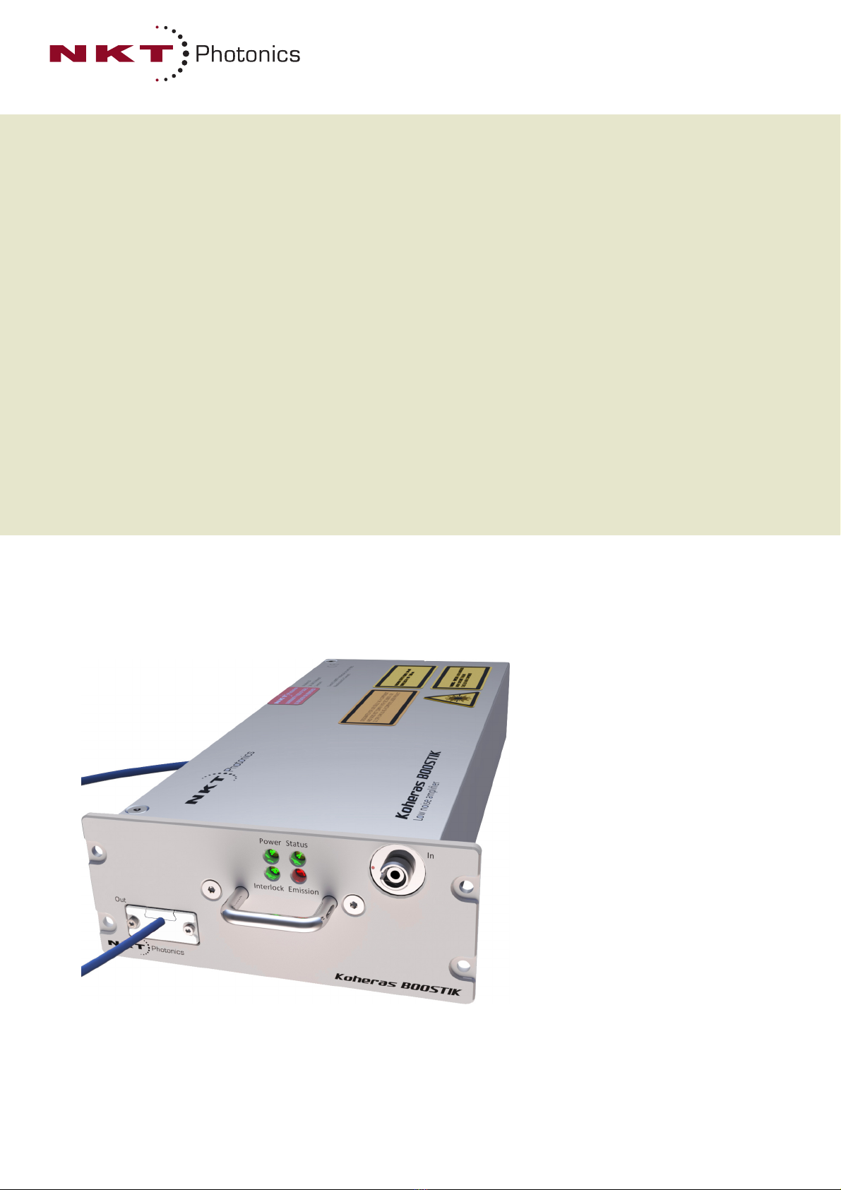
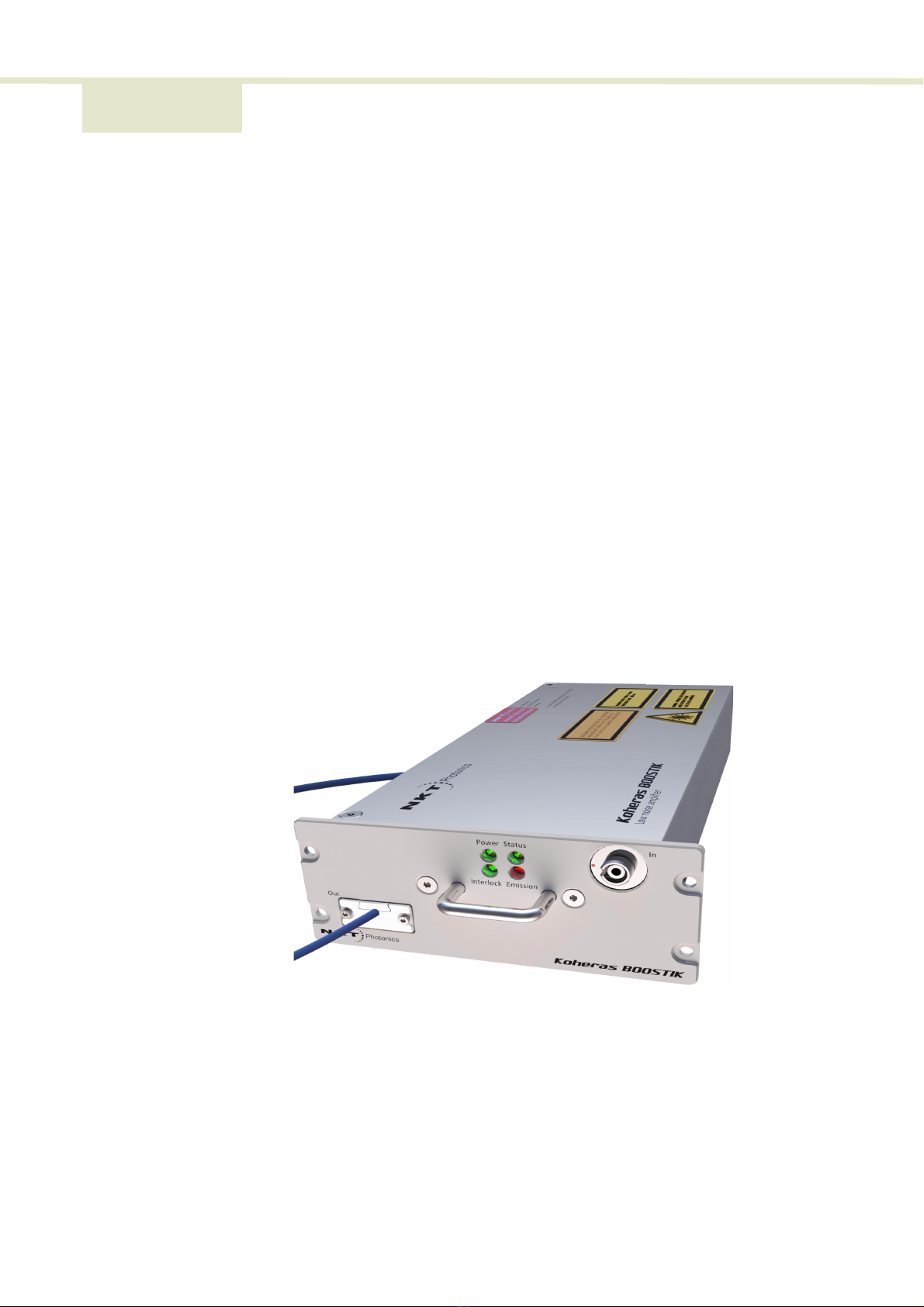
1 Description
The Koheras BOOSTIK LC is a compact fiber amplifier module for low-noise, narrow-
linewidth Koheras seed lasers. The module is designed as a line card component of
a complete laser system. The module inserts into a Koheras ACOUSTIK 16-slot rack
shelf where it occupies two slots.
The ACOUSTIK shelf provides power and communications to the BOOSTIK LC
module and it also houses a seed laser such as a Koheras BASIK. The optical output
fiber of a Koheras BASIK seed laser connects to the optical input of a BOOSTIK LC
module where the light is amplified before exiting from its optical output fiber and
finally the standard FC/APC connector.
The amplifier module operates in the 1060-1075 nm or 1545-1565 nm wavelength
range. Depending on the variant, the amplifier is designed to extend the output
power of its seed laser to either 200 mW or 2 W output power. The amplifier
achieves this while preserving the seed laser’s ultra-low noise and narrow linewidth
optical output.
The rear panel of a BOOSTIK LC module includes an electrical connector. The
connector is designed to mate with an ACOUSTIK backplane connector when
inserted into the shelf. Using NKT Photonics CONTROL software, all inserted
modules in the shelf are controlled from a single ACOUSTIK interface through either
USB or Ethernet connectivity.
Figure 1 BOOSTIK LC general view - front and rear panels
Note: A BOOSTIK LC module can also be implemented as a component in custom la-
ser systems. For these applications, NKT Photonics’ SDK is available to integrate the
module with the system control platform.

Front and rear panels
16
Variants Three different BOOSTIK LC variants are available and mainly characterized by their
output power and center wavelength. Their specific characteristics can be seen in
Table 1 below.
Table 1 BOOSTIK LC variants and their characteristics
Front and rear panels
Front panel The front panel shown in Figure 2 includes optical output and input fiber connectors
and status LEDs. The output fiber and connector (see table TBD) is fitted at the
factory.
See Table 1 on page 16 for more information on the optical outputs and connector
configuration.
The status LEDs on the front panel indicate the following states:
• Power – the supply voltage status
• Interlock – interlock circuit open/closed (not OK/OK)
• Emission – the laser emission status (enabled or disabled)
• Status – the module stability status
For more information see “Status LEDs” on page 20.
Variant: 2 W@ 1550 nm 200 mW @ 1550 nm 200 mW @ 1064 nm
Compatible Koheras seed laser(s) E15, X15,C5 E15, X15,C5 Y10
Operation mode CWi
i. Continuous Wave - inherently single frequency
CWiCWi
Operating wavelength [nm] 1545 to 1565 1545 to 1565 1060 to 1075
Input power [mW] 1 to 50 10 to 50 10 to 50
Output power [mW] 2000 200 200
Output power tunability [%] 10 to 100 10 to 100 10 to 100
Polarization PMii or SMiii
ii. Polarization Maintaining
iii. Singe Mode
PMii PMii
Input and output optical
termination FC/APCiv
iv. E2000 optional
FC/APCiv FC/APCiv
Output fiber type PM1550 or SMF28 PM1150 PM980
2

17
Front and rear panels
Figure 2 BOOSTIK LC front panel layout
Koheras ACOUSTIK faceplate
The faceplate is mounted onto the front panel of the module casing and has four
screw holes that align with the mounting holes of the ACOUSTIK slots. Once inserted
into the ACOUSTIK, the module is fastened securely using four M4x0.7 screws.
Figure 3 Inserting a BOOSTIK LC into an ACOUSTIK shelf
Input fiber connector
A threaded E2000 input connector. The connector is designed to received the seed
optical signal from a BASIK module.
1 Koheras ACOUSTIK faceplate 4 Output fiber and connector
2Status LEDs 5Handle
3 Input fiber connector (from BASIK) TBD
type?
45
123
2
3
12
4x M4x0.7
Front and rear panels
18
Output fiber and connector
The optical output aperture fibers and connectors are specified in Table 1.
Handle
Grip the handle firmly, when inserting and removing the BOOSTIK LC from a slot in
the ACOUSTIK shelf.
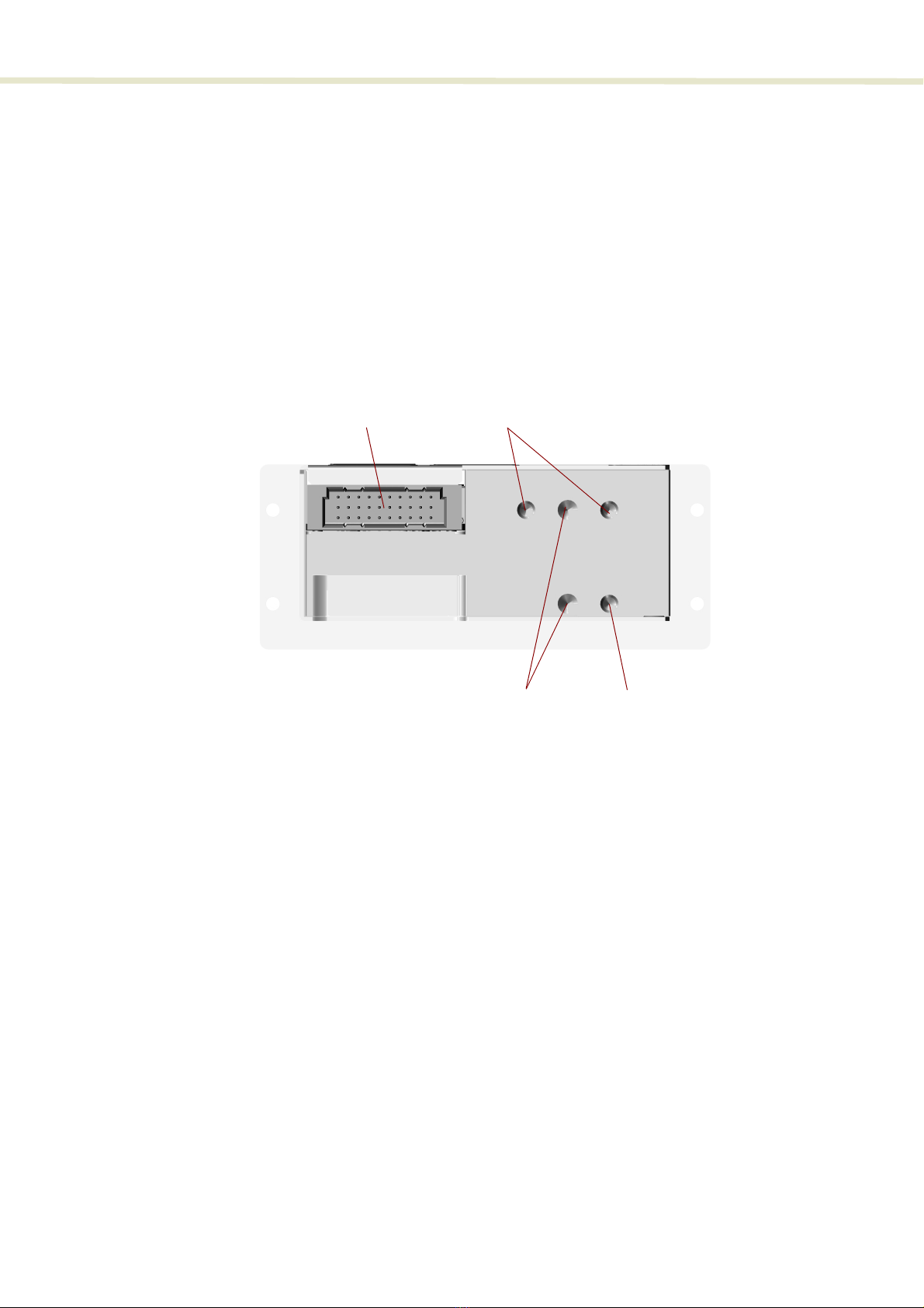
Rear panel The rear panel, shown in Figure 4, it includes the main electrical interface, alignment
holes, a heat transfer surface and three M4 tapped holes for fastening the laser from
the rear.
Figure 4 BASIK rear panel layout
Main electrical Interface
Caution: The main electrical interface is a 30-pin male C/3 connector located on the
rear panel of the module. The interface includes pins for the following signals:
• Serial communication – RS-485
• Interlock – to support the
• Emission control
• Modulation input/output – wavelength modulation
For a complete description of the pin assignments , see “Main electrical interface” on
page 91.Laser Control.
1 Main electrical interface – C3 3 Alignment holes
2 M4 mounting screw holes
2
3
12

19
Front and rear panels
CONTROL GUI You can manage the BOOSTIK LC laser amplifier and all other modules inserted into
an ACOUSTIK shelf using NKT Photonics CONTROL graphical user interface (GUI)
software installed on a PC. The PC is connected to the ACOUSTIK through either an
USB or Ethernet connection.
To connect to an access a BOOSTIK LC module, follow the procedures to connect
CONTROL to the ACOUSTIK shelf described in the document:
Koheras ACOUSTIK Product Guide
Once connected, use the software to control and monitor the amplifier emission. The
amplifiers status and errors can also be viewed. For more information, refer to the
chapter: “CONTROL GUI” on page 29.
Generic UI and NKT
Photonics SDK
The Generic User Interface or Generic UI is control interface software intended for
setting and monitoring the BOOSTIK LC registers. Registers are set or monitored
through the Interbus protocol of the NKT Photonics SDK.
The SDK and Generic UI are intended for integration of the laser with a custom-built
control system. The Generic UI platform provides a convenient interface useful
during development and deployment. Instructions on how to use the Generic UI and
Interbus protocol can be found in the SDK user manual included with the kit.
For BOOSTIK LC error codes and status bits, see Appendix D.
Enabling emission The BOOSTIK LC is intended for use as a component in an ACOUSTIK shelf as part
of a complete laser system. To enable emission from the module, refer to the
procedures in the document:
Koheras ACOUSTIK Product Guide

Front and rear panels
20
Status LEDs
The rear panel houses four status LEDs that behave as described in Table 2. The
LEDs are located on the center top of the front panel as shown in Figure 5.
Figure 5 Status LEDs
Table 2 Status LEDs
Note: DONOT OPERATE the laser until you are familiar with the controls and have taken
all precautions necessary as described in the Koheras BOOSTIK LC-series Laser
Safety, Handling and Regulatory Information.
Emission
Interlock Status
Power
LED Name Condition Description
Power ON Green DC Voltage at the DC power input pins is OK.
ON Red DC voltage at the DC power input pins is too low.
Flashing Amber The module is transmitting data.
OFF No DC power at the module power input pins.
Emission ON Red Laser amplifier emission is ON.
OFF Laser amplifier emission is OFF.
Status ON Green Output power OK
ON Amber Module ready
Interlock ON Green The interlock status is OK – the door circuit is
closed and energized.
ON Red The interlock status is Not OK – the door circuit is
open or not energized.
Other manuals for Koheras BOOSTIK LC
1
Table of contents
Other NKT Photonics Amplifier manuals


