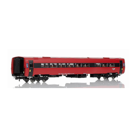
NMJ B3 Series User manual

B3 series lighting board
assembly guide
- version 0.1.4 –
© Copyright NMJ 2016
All rights reserved

B3 series lighting board
assembly guide
Version
0.1.4
Page 2 of 23
Please read this manual carefully before carrying out the
installation!!! Although our products are very robust, incorrect
wiring may destroy the module!
During the operation of the device the specified technical parameters
shall always be met. At the installation the environment shall be fully
taken into consideration. The device must not be exposed to moisture
and direct sunshine.
A soldering tool may be necessary for the installation and/or
mounting of the devices, which requires special care.
During the installation it shall be ensured that the bottom of the
device should not contact with a conductive (e.g. metal) surface!

B3 series lighting board
assembly guide
Version
0.1.4
Page 3 of 23
Content
1. Required tools..............................................................................4
2. Required materials.......................................................................4
3. Disassembly of the coaches.........................................................5
4. Installing the current pickups and changing the wheels..............8
5. Adjusting and fitting the interior...............................................12
6. Assembly the lighting board......................................................14
7. Tail light connection..................................................................16
8. Notes..........................................................................................22

B3 series lighting board
assembly guide
Version
0.1.4
Page 4 of 23
1. Required tools
- tweezer
- marker pen
- plier
- cutting plier
- cutter
- soldering station
- 1.2-1.5-2.0 mm drill bit with holder
2. Required materials
- B3 lighting kit containing:
- Shine Plus Maxi, B3 version x1
- 220uF/25V capacitors x2
- B3 wheels/axles x4
- B3 current pickups with wires x2
- Brass auxiliary tool x1
- adhesive tape
- soldering wire
- cyanoacrylate (optional)
- Shine Plastic supports (2 pcs optional)
- Shine Micro R boards (2 pcs optional) for tail lights
- isolated conductor wires 2x30 mm for each tail light
- fine sandpaper (optional)
Estimated assembly time: 20-25 minutes

B3 series lighting board
assembly guide
Version
0.1.4
Page 5 of 23
3. Disassembly of the coaches
The roof of the carriages has to be removed first. Press the roof from
both sides in direction (1) and lift it above the body (2).
Some of the B3 carriages have interior walls up to the level of the
carriage body, others (as the BF11 road number 21524, article
108.101, used in the illustrations) has interior wall up to the roof
level.
In the case of higher interior walls, their height has to be adjusted to
allow space to fit the lighting boards.
1
1
1
1
2
2

B3 series lighting board
assembly guide
Version
0.1.4
Page 6 of 23
Before extracting the interior, using a marker pen, mark the
adjustment line. This should be situated 2-3 mm above the level of
the body. We will use later this mark while we adjust the height of
the walls.
The interior is kept in place by 2 plastic pins at the end of the bodies
(1). If the middle of the interior is pulled in upper direction (2), the
pins will release the interior, and it can be removed easily.
In most of the cases, the interior is glued with several glue drops to
the body, so firmly movements will be necessary while removing it.
1
1
2

B3 series lighting board
assembly guide
Version
0.1.4
Page 7 of 23
Interior during removing:
Completely removed interior:

B3 series lighting board
assembly guide
Version
0.1.4
Page 8 of 23
4. Installing the current pickups and changing
the wheels
Using a small screwdriver and a tweezer, remove the 2 axle pairs
from each boogie.
Insert the supplied current pickups on each of the boogies. Fit the 4
holes of the current pickup to the plastic pins of the boogie. A small
drop of cyanoacrylate can be used to keep in place the current
pickups.

B3 series lighting board
assembly guide
Version
0.1.4
Page 9 of 23
Holding the supplied brass auxiliary tool over the small plastic pins
with a tweezer, melt them with the soldering iron. This will keep
safely the current pickups in their place. Do not touch the plastic
parts of the boogie or the carriage with the tip of the soldering iron!
Insert the wires in the central hole of the current pickup, and lead
them to the interior of the body. Pull them completely inside the
body.

B3 series lighting board
assembly guide
Version
0.1.4
Page 10 of 23
Lead the wires at the bottom level of the housing. Keep them in place
with some small drops of cyanoacrylate. Do not leave them loose,
else they will disturb the movement of the close coupling mechanism.
They should be lead to the roof level in the corner of the body,
between the transparent window pieces.
Before inserting the new wheels into the boogies, bend both sides of
the current pickups in upper direction with a plier, as it can be seen in
the illustrations below. This will ensure a proper contact to the axles.
Insert 2 of the supplied new axles into each boogie.

B3 series lighting board
assembly guide
Version
0.1.4
Page 11 of 23
The current pickups will collect one track polarity on each boogie.
Therefor the isolation of each of the axles of one boogie must be on
the same side. The isolations on the boogies must be opposite.
Possible solutions are illustrated below:
Any of the above situations will result in a correct operation. Mixing
the isolation on the same boogie will produce short circuit of the
DCC system.
Isolation
Isolation
Isolation
Isolation

B3 series lighting board
assembly guide
Version
0.1.4
Page 12 of 23
5. Adjusting and fitting the interior
Using a cutter and a cutting plier, adjust the interior walls to the
marking line. Perform the adjustments with small cuts, and use the
cutter to level the surface.
Insert the interior into the body of the carriage, and let the 2 pins at
the end to keep it in place.

B3 series lighting board
assembly guide
Version
0.1.4
Page 13 of 23
Optionally you can use 2 Plastic Shine supports, and insert them
inside the interior of the carriage. Use cyanoacrylate to glue them to
the walls of the interior. Adjustment of the length of the U shaped
plastic support might be necessary.

B3 series lighting board
assembly guide
Version
0.1.4
Page 14 of 23
6. Assembly the lighting board
Fit the Shine Plus B3 board over the interior, and find the proper
place for the capacitors. One possible solution is illustrated.
Please note the polarity of the capacitors, and connect them
according to the Shine Plus manual. Cut the excess of the capacitors
terminals.
Connect the wires from the current pickups to the Shine Plus board.
If necessary keep them in place with a small drop of cyanoacrylate or
with the use of adhesive tape.

B3 series lighting board
assembly guide
Version
0.1.4
Page 15 of 23
Insert the roof over the body and secure it by pressing against the
housing.
Short overview of some assembled B3 carriages:

B3 series lighting board
assembly guide
Version
0.1.4
Page 16 of 23
7. Tail light connection
The construction of the B3 carriage housing allows the assembly of
tail lights at each end of the carriages. Remove the double wall from
the housing by simply pulling it out.
As it can be seen, it is kept in place by 2 plastic pins (1, next page
figure).

B3 series lighting board
assembly guide
Version
0.1.4
Page 17 of 23
The light guides have a 3 mm excess in the back side of the wall (2).
Level the light guides with a cutter to the same plane as the walls.
Their surface can be adjusted/finished with a piece of fine sand
paper.
1
1
2
2

B3 series lighting board
assembly guide
Version
0.1.4
Page 18 of 23
The tail lights will use 2 Shine Micro R boards. Wire them as it is
illustrated. The wire length is approximately 30 mm for both
conductors. Please respect the polarity of the connections. The 2
Shine Micro R boards are wired in mirror as it is illustrated..
Glue the 2 Shine Micro R boards to the end wall of the carriage using
a few drop of cyanoacrylate.

B3 series lighting board
assembly guide
Version
0.1.4
Page 19 of 23
Mark the level of the double wall at the back of the carriage using a
marker pen.
Drill a 2 mm hole in the back of the carriage in the center symmetry
line of the wall.

B3 series lighting board
assembly guide
Version
0.1.4
Page 20 of 23
Insert the double end wall to the back side of the carriage while
leading the 2 wire pairs in vertical position.
Lead the 2 wire pairs from the Shine Micro R boards through the 2
mm hole to the Shine Plus Maxi board.
Table of contents
Other NMJ Toy manuals

