Noark Electric Ex9EMS 1P 2M 100A 1T User manual

Copyright Noark Electric 2018. All Rights Reserved. www.noark-electric.eu
Noark Electric Europe s.r.o., Sezemicka 2757/2, Prague, Czech Rep.
Ex9EMS 1P 2M 100A 1T
Ex9EMS 1P 2M 100A 2T
Ex9EMS 1P 2M 100A MB 2T
Ex9EMS 1P 2M 100A MO 2T
Smart Energy Meters

1 Index
Contents
1 Index ..................................................................................................2
2 Safety instructions ......................................................................................3
3 Specications ..........................................................................................4
3.1 Dimensions ..................................................................................................4
3.2 Connection diagram .........................................................................................4
4 Installation .............................................................................................5
5 Operation ..............................................................................................6
5.1 Energy ow indication .......................................................................................6
5.2 Reactive energy indication ...................................................................................6
5.3 Tari indication ..............................................................................................6
5.4 Reading the meter ...........................................................................................6
5.5 LCD display of the meter .....................................................................................6
5.6 Scrolling function ............................................................................................7
5.7 Button scroll .................................................................................................8
5.8 Backlight ....................................................................................................9
5.9 Resettable day counter .......................................................................................9
5.10 S0 output rate ..............................................................................................9
5.11 Combination code .........................................................................................10
5.12 Modbus/M-bus ID .........................................................................................10
5.13 Baud rate ..................................................................................................11
5.14 Parity ......................................................................................................11
5.15 Power down counter.......................................................................................11
5.16 Password ..................................................................................................12
5.17 OBIS codes ................................................................................................12
6 Troubleshooting .......................................................................................13
6.1 List of errors in display.......................................................................................13
Appendix 1 - Ex9EMS 1P 2M 100A 2T......................................................................14
A1.1 How to switch between T1 and T2 ..........................................................................14
Appendix 2 - Ex9EMS 1P 2M 100A MB 2T ..................................................................15
A2.1 Communicating via the M-bus output......................................................................15
A2.2 M-bus register map .......................................................................................16
Appendix 3 - Ex9EMS 1P 2M 100A MO 2T ..................................................................17
A3.1 Communicating via the Modbus output ....................................................................17
A3.2 Modbus register map ......................................................................................18
NOARK Ex9EMS 1P 2M - 2

1 Index 2 Safety instructions
Information for your own safety
This manual does not contain all of the safety measures for operation of this meter because special operating conditions, local
code requirements or local regulations may necessitate further measures. However, it does contain information which must be
adhered to for your own personal safety and to avoid material damage. This information is highlighted by a warning triangle
with an exclamation mark or a lightning bolt depending on the degree of actual or potential danger:
Warning
This means that failure to observe the instruction can result in death, serious injury or considerable
material damage.
Caution
This means hazard of electric shock and failure to take the necessary safety precautions will result in
death, serious injury or considerable material damage.
Qualied personnel
Installation and operation of the device described in this manual may only be performed by qualied personnel. Only people
that are authorized to install, connect and use this device, who have the proper knowledge about labeling and grounding elec-
trical equipment and circuits and can do so in accordance with local (safety)regulations, are considered qualied personnel in
this manual.
Use for the intended purpose
This device may only be used for the application cases specied in the catalog and the user manual and only in
connection with devices and components recommended and approved by NOARK Electric.
Proper handling
The prerequisites for perfect, reliable operation of the product are proper transport, storage, installation and connection, as well
as proper operation and maintenance. During its operation certain parts of the meter might carry dangerous voltages.
• Only use insulated tools suitable for the voltages this meter is used for.
• Do not connect while the circuit is connected to a power or current source.
• Only place the meter in a dry environment.
• Do not mount the meter in an explosive area or exposed to dust, mildew and/or insects.
• Make sure the used wires are suitable for the maximum current of this meter.
• Make sure the AC wires are connected correctly before activating the current/voltage to the meter.
• Do not touch the meter’s connection clamps directly with your bare hands, with metal, blank wire or other
conducting material as you will risk an electric shock that could cause possible injury, serious injury or death.
• Make sure the protection covers are replaced after installation.
• Maintenance and repair of the meter should only be carried out by qualied personnel.
• Never break any seals (if present on this meter) to open the front cover as this might inuence the functionality or accu-
racy of the meter, and will void all warranty.
• Do not drop, or allow physical impact to the meter as there are high precision components inside that may break and
aect the meter measurement negatively.
• All clamps should be properly tightened.
• Make sure the wires t properly in the connection clamps.
• If the wires are too thin it will cause a bad contact which can spark causing damage to the meter and its
surroundings.
NOARK Ex9EMS 1P 2M - 3

3.1 Dimensions
Height 92,5 mm
Width 35,8 mm
Depth 63 mm
Max. diameter power connection clamps 35 mm2
(Solid copper)
Weight 0,16 Kg (net)
3Specications
3.2 Connection diagram
Connection of the wires should be done in accordance with the connection diagram as shown below:
1 Phase line in (L-IN)
3 Phase line out (L-OUT)
4 Neutral line in (N)
6 Neutral line out (N)
10 & 11 M-bus/Modbus communication contact (Ex9EMS 1P 2M 100A MB 2T & Ex9EMS 1P 2M 100A MO 2T only)
12 & 13 External tari input (Ex9EMS 1P 2M 100A 2T only)
18 & 19 Pulse output contact (S0) forward
20 & 21 Pulse output contact (S0) reverse
NOARK Ex9EMS 1P 2M - 4

3Specications
• The connecting wire, connecting the device to the outside circuit, should be sized in accordance with local
regulations for the maximum amount of the current breaker or other overcurrent protection devices used in the circuit.
• An external switch or a circuit-breaker should be installed on the supply wires, which will be used to disconnect the
meter and the device supplying energy. It is recommended that this switch or circuit-breaker is placed near the meter
because that is more convenient for the operator. The switch or circuit-breaker should comply with the specications of
the building’s electrical design and all local regulations.
• An external fuse or thermal cut-o used as an overcurrent protection device for the meter must be installed on the
supply side wires. It’s recommended that this protection device is also placed near the meter for the convenience of the
operator. The overcurrent protection device should comply with the specications of the building’s electrical design and
all local regulations.
• The meter is intended to be installed in a Mechanical Environment ‘M1’, with Shock and Vibrations of low signicance
and Electromagnetic Environment ‘E2’, as per 2014/32/EC Directive. The meter shall be installed inside a suitable IP rated
enclosure, in accordance with local codes and regulations.
• To prevent tampering, an enclosure with a lock or a similar device can be used.
• The meter has to be installed against a re resistant wall.
• The meter has to be installed in a well-ventilated and dry place.
• The meter has to be installed in a protective box if the meter is exposed to dust or other contaminants.
• The meter can be installed and used after being tested and can be sealed afterwards.
• The device can be installed on a 35mm DIN rail.
• The meter should be installed on a location where the meter can be read easily.
• In case the meter is installed in an area with frequent surges for example due to thunderstorms, welding
machines, inverters etc., the meter is required to be protected with a Surge Protection Device.
• The device should be sealed immediately after installing it in order to prevent tampering.
4 Installation
NOARK Ex9EMS 1P 2M - 5
Caution
• Turn o and if possible lock all sources supplying the energy meter and the equipment that is connected to it before
working on it.
• Always use a properly rated voltage sensing device to conrm that power is o.
Warning
• The installation should be performed by qualied personnel familiar with applicable codes and regulations.
• Use insulated tools to install the device.
• A fuse, thermal cut-o or single-pole circuit breaker should be tted on the supply line and not on the neutral line.

5.1Energyowindication
The red LED on the front panel indicates the power ow measured by the meter. When power ows, the LED will ash. The faster
the LED ashes, the more power ows. For this meter, the LED will ash 10.000 times per kWh. The rst display indication of the
meter in the scrolling mode is either FW (forward) or RV (reverse).
5.2 Reactive energy indication
The display will show kvarh to indicate the meter is measuring reactive energy.
5.3Tariindication
The LCD will show T2 in the right upper corner to indicate tari 2 is active.
5.4 Reading the meter
A red LED on the front panel indicates the consumption measured by the meter. When power is consumed, the LED will ash.
The faster the LED ashes, the more power is consumed. For this meter, the LED will ash 10.000 times per kW.
The meter is equipped with a 7 digit LCD. For the energy consumption the meter will display 99999.99 kWh and switch to
999999.9 kWh when over this value and so on.
5.5 LCD display of the meter
The LCD display has three rows. The upper row contains tari indication, energy ow direction, communication and unit. The
middle row is used to show the value per unit. The lower row is used to show al other metering info or OBIS codes.
5 Operation
NOARK Ex9EMS 1P 2M - 6

5 Operation
5.6 Scrolling function
5.6.1 Automatic scroll
Every 10 seconds the meter will display the next programmed data page (depending on the setting).
5.6.2 Change scrolling time by button
• Scroll with the buttons to Program mode 2.
• Hold the right button for 3 seconds to enter the menu.
• Scroll to LCD page LCD cycle time (SEC xx).
• Hold the right button for 5 seconds to enter program mode.
• The value starts blinking: select the new value 1-30 seconds.
• Conrm the new scrolling time by holding both buttons for 3 seconds.
• The LCD will show OK when the setting is conrmed.
5.6.3 Add/remove registers to/from automatic scroll
• Scroll to the register* that you would like to add or remove.
• Hold the right button for 5 seconds to add or remove.
• The LCD will show OK in or OK out.
*Only the registers in the sub-menu after: Total active energy, Total reactive energy, Active power and Program mode 1 can be added or removed to/from
the automatic scroll. Total active energy cannot be removed.
NOARK Ex9EMS 1P 2M - 7
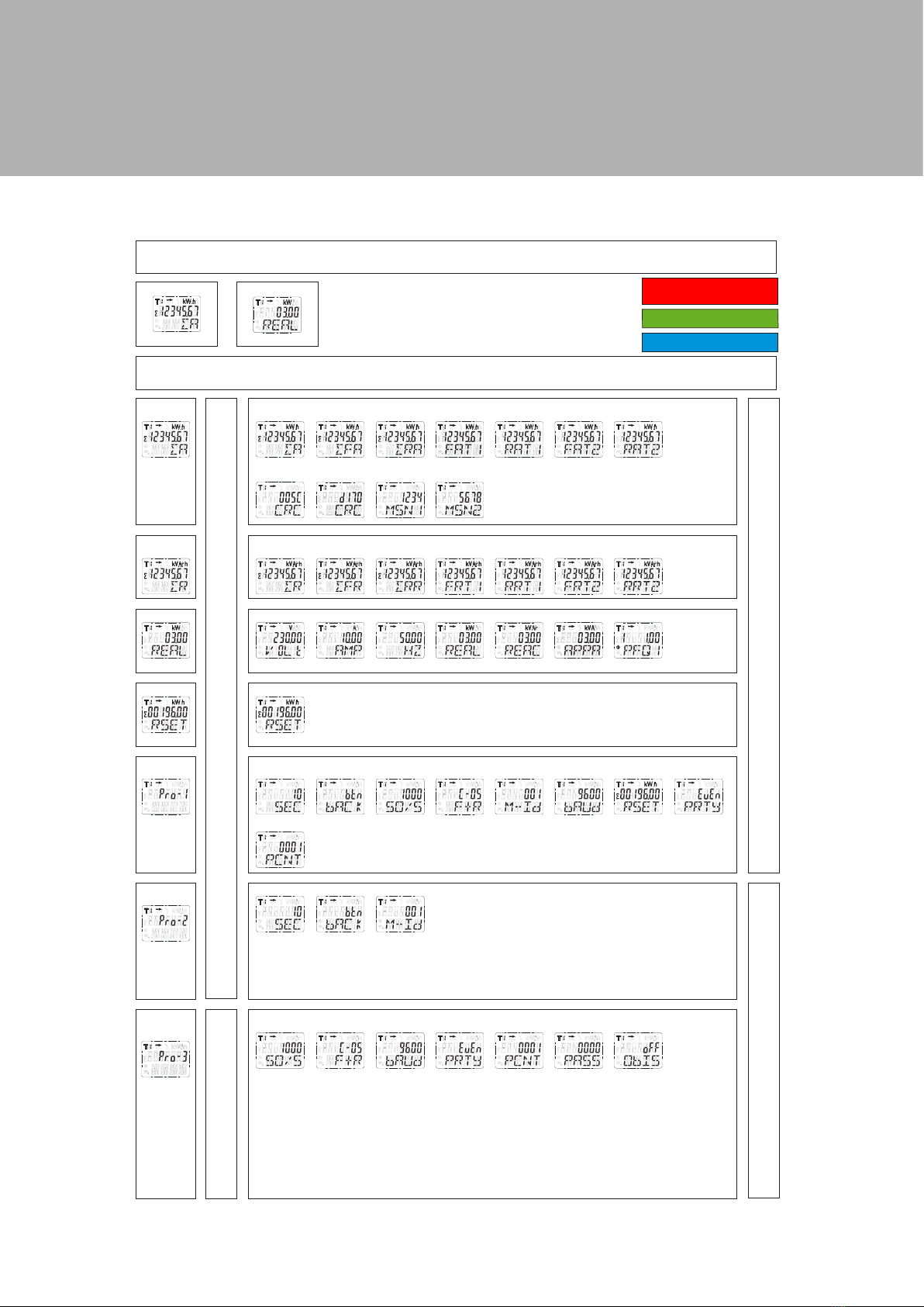
5.7 Button scroll
By pressing the button for 1, 3 or 5 seconds you will go through all data pages one by one.
NOARK Ex9EMS 1P 2M - 8
Automatic scroll: default 10 seconds
Total active energy Active power
Total active
energy
Total active
energy
Total forward
active energy
Total reverse
active energy
T1 forward
active energy
T1 reverse
active energy
T2 forward
active energy
T2 reverse
active energy
Program verify sum Meter serial number
Total reactive
energy
Total reactive
energy
Total forward
reactive energy
Total reverse
reactive energy
T1 forward
reactive energy
T1 reverse
reactive energy
T2 forward
reactive energy
T2 reverse
reactive energy
Active power Voltage Current Frequency Active power Reactive power Apparent power Power factor
Resettable kWh Resettable kWh
Hold the right button
for 5 seconds to reset.
Program mode 1
(read only)
Program mode 2
(write)
Program mode 3
(Write: password
protected)
LCD cycle time Backlight S0 output Combination
code
Modbus/M-bus
ID
Baud rate Resettable kWh Parity
Power down counter
LCD cycle time Backlight Modbus/M-bus ID
S0 output Combination
code
Baud rate Parity Power down
counter
Password OBIS codes
Hold
the
right
button
for 3
seconds
to
enter
the
next
menu.
Hold
the
left
button
for 3
seconds
to go
back.
Display
Shows:
>>
or
<<
Hold
the
right
button
for ≥5
seconds
to add
or
remove
from
the
auto-
matic
scroll.
Display
Shows:
OK IN
or
OK OUT
Hold
the
right
button
for ≥5
seconds
to
enter
program
mode.
Hold
the
right
button
for 3
seconds
and
enter 4
digit
pass-
word
to
enter
program
mode.
Scroll with the
buttons to select
10.000/2.000/
1.000/100/10/
1/0,1/0,01.
Hold both buttons
for 3 seconds
to conrm.
Hold both buttons
for 3 seconds
to conrm.
Hold both buttons
for 3 seconds
to conrm.
Hold both buttons
for 3 seconds
to conrm.
Hold both buttons
for 3 seconds
to reset.
Hold both buttons
for 3 seconds
to conrm.
Hold both buttons
for 3 seconds
to conrm.
Hold both buttons
for 3 seconds
to conrm.
Conrm each
digit by holding
both buttons for
3 seconds
Scroll with the
buttons to select
300/600/1200/
4800/9600.
Scroll with the
buttons to select
even/none/odd.
Scroll with the
buttons to select
01(F)/04(R)/
05(F+R)/06(R-F)/
09(F-R)/10(F-R).
Select the new
4 digit password
by choosing each
digit (0-9).
Select
ON or OFF.
Button scroll: press the buttons for less than 3 seconds to scroll. After 30 seconds of no interaction the meter goes back to automatic scroll mode.
Scroll with the
buttons to select
1-30.
Scroll with the
buttons to select
on/o button.
Scroll with the
buttons to select
3 digits.
Conrm each digit
by holding both
buttons for 3 seconds.
Ex9EMS 1P 2M 100A 2T
Ex9EMS 1P 2M 100A MB 2T
Ex9EMS 1P 2M 100A MO 2T
Ex9EMS 1P 2M 100A MB 2T
Ex9EMS 1P 2M 100A MO 2T
Ex9EMS 1P 2M 100A MO 2T

5.8 Backlight
The meter is equipped with a blue backlight. The backlight can be set to always on, o or button mode.
5.8.1 Change the backlight setting
• Scroll with the buttons to Program mode 2.
• Hold the right button for 3 seconds to enter the menu.
• Scroll to LCD page Backlight setting (bACK xx).
• Hold the right button for 5 seconds to enter program mode.
• The value starts blinking: select button/on/o.
• Conrm the new setting by holding both buttons for 3 seconds.
• The LCD will show OK when the setting is conrmed.
5.9 Resettable day counter
The meter is equipped with a day counter for consumed energy. This is the energy forward calculated and can be reset to zero
by the user.
5.9.1 How to reset the day counter back to 0
• Scroll to register Resettable kWh in the main menu.
• Hold the right button for 3 seconds to enter the menu.
• The value starts blinking: hold the right button for 5 seconds to reset.
• The LCD will show OK when the value is reset.
5.10 S0 output rate
The energy meter is equipped with two pulse outputs (forward and reverse) which are optically isolated from the
inside circuit. It generates pulses in proportion to the measured consumption for purpose of remote reading or accuracy tes-
ting. The pulse output is a polarity dependent, open-collector transistor output requiring an external voltage source for correct
operation. For this external voltage source, the voltage (Ui) should be lower than 27V DC. The maximum switching current
(Imax) is 100mA. To connect the impulse output, connect 5-27V DC to connector 18/20 (collector), and the signal wire (S) to
connector 19/21 (emitter).
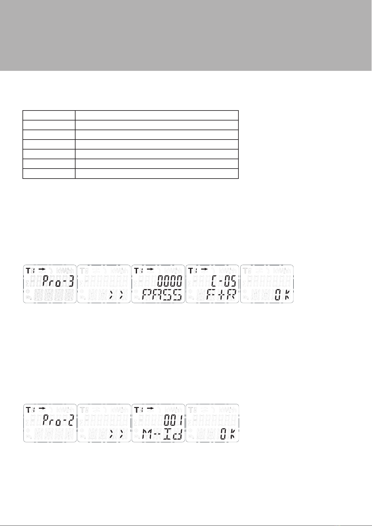
5.10.1 How to change the S0 output rate
• Scroll with the buttons to Program mode 3.
• Hold the right button for 3 seconds to enter the menu.
• Enter the 4 digit password: scroll with the buttons and select each digit 0-9, hold the right button for 3 seconds to
conrm each digit.
• Scroll to LCD page S0 output (S0 xxxxxx).
• Hold the right button for 5 seconds to enter program mode.
• The value starts blinking: select 10.000/2.000/1.000/100/10/1/0,1/0,01.
• Conrm the new setting by holding both buttons for 3 seconds.
• The LCD will show OK when the setting is conrmed.
NOARK Ex9EMS 1P 2M - 9
5.11 Combination code
The meter allows you to display the total energy (usage) shown on the display in accordance to dierent calculation methods.
You can use the following calculation methods for total energy:
Code Total (active) energy
C-01 Forward only
C-04 Reverse only
C-05 Forward + Reverse
C-06 Reverse - Forward
C-09 Forward - Reverse
C-10 Forward - Reverse
5.11.1 How to change the combination code
• Scroll with the buttons to Program mode 3.
• Hold the right button for 3 seconds to enter the menu.
• Enter the 4 digit password: scroll with the buttons and select each digit 0-9, hold the right button for 3 seconds to conrm
each digit.
• Scroll to LCD page Combination code (C-xx).
• Hold the right button for 5 seconds to enter program mode. The value starts blinking:
select 01/04/05/06/09/10.
• Conrm the new setting by holding both buttons for 3 seconds.
• The LCD will show OK when the setting is conrmed.
5.12 Modbus/M-bus ID
The Modbus ID can be set from 001 to 247, the default Modbus ID is 001. The M-bus ID can be set from 000 to 250, the default
M-bus ID is 000.
5.12.1 How to change the Modbus/M-bus ID
• Scroll with the buttons to Program mode 2.
• Hold the right button for 3 seconds to enter the menu.
• Scroll to LCD page Modbus/M-bus ID (M-- Id xxx).
• Hold the right button for 5 seconds to enter program mode.
• The value starts blinking: select 3 digits (Modbus: 001-247 or M-bus: 000-250). Conrm each digit by holding both
buttons for 3 seconds.
• The LCD will show OK when the setting is conrmed.
NOARK Ex9EMS 1P 2M - 10

5.13 Baud rate
The Modbus baud rate can be set from 1200 to 9600. The M-bus baud rate can be set from 300 to 9600.
5.13.1 How to change the baud rate
• Scroll with the buttons to Program mode 3.
• Hold the right button for 3 seconds to enter the menu.
• Enter the 4 digit password: scroll with the buttons and select each digit 0-9, hold the right button for 3 seconds to
conrm each digit.
• Scroll to LCD page Baud rate (M bAud xxxx).
• Hold the right button for 5 seconds to enter program mode.
• The value starts blinking: select 9600/4800/2400/1200/600/300.
• Conrm the new setting by holding both buttons for 3 seconds.
• The LCD will show OK when the setting is conrmed.
5.14 Parity
The Modbus parity can be set to even, none or odd. The M-bus parity is always even.
5.14.1 How to change the parity
• Scroll with the buttons to Program mode 3.
• Hold the right button for 3 seconds to enter the menu.
• Enter the 4 digit password: scroll with the buttons and select each digit 0-9, hold the right button for 3 seconds to
conrm each digit.
• Scroll to LCD page Parity (PArity xxxx).
• Hold the right button for 5 seconds to enter program mode.
• The value starts blinking: select even/none/odd.
• Conrm the new setting by holding both buttons for 3 seconds.
• The LCD will show OK when the setting is conrmed.
5.15Powerdowncounter
The power down counter registers the number of times that the meter has been turned o.
5.15.1 How to reset the power down counter
• Scroll with the buttons to Program mode 3.
• Hold the right button for 3 seconds to enter the menu.
• Enter the 4 digit password: scroll with the buttons and select each digit 0-9, hold the right button for 3 seconds to
conrm each digit.
• Scroll to LCD page Power down counter (PCNT xxxx).
• Hold the right button for 5 seconds to enter program mode.
• The value starts blinking: hold both buttons for 3 seconds to reset.
• The LCD will show OK when the value is reset.
NOARK Ex9EMS 1P 2M - 11

5.16Password
Program mode 3 is protected with a password. The default password is 0000.
5.16.1 How to change the password
• Scroll with the buttons to Program mode 3.
• Hold the right button for 3 seconds to enter the menu.
• Enter the 4 digit password: scroll with the buttons and select each digit 0-9, hold the right button for 3 seconds to
conrm each digit.
• Scroll to LCD page Password (PASSrd xxxx).
• Hold the right button for 5 seconds to enter program mode.
• The value starts blinking: select each digit 0-9, conrm each digit by holding both buttons for 3 seconds.
• The LCD will show OK when the setting is conrmed.
5.17 OBIS codes
For OBIS codes on the LCD you can turn the OBIS mode ON in Program mode 3. The default setting for OBIS codes is OFF.
5.17.1 How to turn the OBIS code ON and OFF
• Scroll with the buttons to Program mode 3.
• Hold the right button for 3 seconds to enter the menu.
• Enter the 4 digit password: scroll with the buttons and select each digit 0-9, hold the right button for 3 seconds to
conrm each digit.
• Scroll to LCD page OBIS (OBIS ON/OFF).
• Hold the right button for 5 seconds to enter program mode.
• The value starts blinking: select ON or OFF.
• Hold both buttons for 3 seconds to conrm.
• The LCD will show OK when the setting is conrmed.
NOARK Ex9EMS 1P 2M - 12

6 Troubleshooting
NOARK Ex9EMS 1P 2M - 13
6.1 List of errors in display
It could be that one of the following errors is displayed on the meter:
Display shows Kind of errors Measures
Err 01 EEPROM error Please contact technical support for a
meter replacement.
Err 02 Program code checksum error Please contact technical support for a
meter replacement.
Problem Possible cause Check/solution
The red consumption LED is not ashing
(PULSE LED).
There is no load connected to the
meter. The load on the line is very low.
Connect a load to the meter. Check with
an Ohm-meter if the load value is very
low.
The register doesn’t count. There is almost no load connected to
the meter.
Check if the red consumption LED is
ashing.
No pulse output. The pulse output is not supplied with
DC power. The pulse output is not con-
nected correctly.
Check the external voltage source (Ui) is
5-27V DC with a voltage meter. Check if
the connection is correct: the 5-27V DC
should be connected to the collector
connection (pin 20+) and the signal wire
(S) to the emitter connection (pin 21-).
The pulse output rate is wrong. Is the correct pulse rate set via the
infrared software or in Program mode 3?
Download or request the software
and use the infrared eye which can be
bought seperately.
If none of the above works, please contact technical support

A1.1HowtoswitchbetweenT1andT2
The meter is equipped with 2 tari functionality which need to be activated by an external voltage connected to the terminals
12/13.
This is an AC voltage between 23 and 24:
Appendix 1 - Ex9EMS 1P 2M 100A 2T Appendix 2 - Ex9EMS 1P 2M 100A MB 2T
NOARK Ex9EMS 1P 2M - 14

Appendix 1 - Ex9EMS 1P 2M 100A 2T
A2.1 Communicating via the M-bus output
The Ex9EMS 1P 2M 100A MB 2T meter is equipped with an M-bus port, the data can be read out via this port. The communicati-
on protocol conforms to the EN13757-3 standard.
The meter can communicate with your PC. In order to read out the meter registers rst install and congure the PC software. Use
an M-bus level converter to connect the PC and the meter. The cable should be connected to terminals 10 and 11. The default
communication address of the meter is 00.
The defaults for M-bus communication are:
• Baud rate 9600
• 8 data bits
• even parity
• 1 stop bit
The secondary addressing (253/FD) is preset to the last 8 digits of the serial number printed on the side of the meter. However
this can be changed to a more convenient number through IR or M-bus communication.
The baud rate can be lowered to values 4800, 2400, 1200, 600 and 300 baud. Data, parity and stop bit cannot be changed.
For the registers used in the meter and how to interpreted the data, please use the M-bus register map on the next page.
More detailed information on M-Bus can be found:
www.m-bus.com
Appendix 2 - Ex9EMS 1P 2M 100A MB 2T
NOARK Ex9EMS 1P 2M - 15

A2.2 M-bus register map
Write
NOARK Ex9EMS 1P 2M - 16
M-bus command
Contents
M-bus register header DIF
M-bus register VIF
Response
Remarks
00 00 00 00 00000000
25 CD INM
01 Version
02 Electricity
02
Number of accesses
00 00 = OK 02 = error
00 00 Always 00 00
10 5B
00
5B 16
68
4B 4B
68 08
00
72
68
xx xx [Data length]
68 08
xx [Address]
72
Datablocks:
Total active energy
0C
04
14 48 60 01
01604814 Energy 10 (Wh) =16048,14kWh
Total active energy T1
8C10
04
23 80 35 00
00358023 Energy 10 (Wh) = 3580,23 kWh
Total active energy T2
8C20
04
91 67 24 01
01246791 Energy 10 (Wh) = 12467,91kWh
Total forward active energy
1C
04
46 13 69 00
00691346 Energy 10 (Wh) = 6913,46 kWh
Forward active energy T1
9C10
04
56 34 12 00
00123456 Energy 10 (Wh) = 1234,56 kWh
Forward active energy T2
9C20
04
90 78 56 00
00567890 Energy 10 (Wh) = 5678,9 kWh
Total reverse active energy
2C
04
68 34 91 00
00913468 Energy 10 (Wh) = 9134,68 kWh
Reverse active energy T1
AC10
04
67 45 23 00
00234567 Energy 10 (Wh) = 2345,67 kWh
Reverse active energy T2
AC20
04
01 89 67 00
00678901 Energy 10 (Wh) = 6789,01 kWh
Checksum
7C 16
xx
16
Baudrate
9600
Databits
8
Parity
Even
Stopbit
1
Address
00
Broadcast primary address
FE (only for read)
Start byte REQ UD2
2
Start byte write commands
5
CRC type
SUM
Terminating symbol
16
HEX
-
Low byte first
-
1 byte
-
CRC settings with checksum
No CRC
-
Default
CRC settings without checksum
REQ UD2
68 xx xx 68 08 xx 72 68 [data length] 68 08 [address] 72
[header] [datablocks] [checksum] 16
Header
Serial number
Manufacturer ID
Version
Medium
Acces number
Status
Signature
REQ_UD2 10 5B xx
Contents
Command part 1
Address
Command part 2
New value
Response
Remarks
Baudrate
68 03 03 68 53
01
-
BB
E5 (new Baud 2400)
B8 = 300; B9 = 600; BA = 1200; BB = 2400; BC = 4800; BD = 9600
Primary address
68 06 06 68 53
01
51 01 7A
01
E5 (new id 01)
000 - 247 write in HEX
Secondary address
68 09 09 68 53
01
51 0C 79
15 01 23 45
E5 (new address 1501 2345)
4 bytes BCD same as read
Tariff mode
68 08 08 68 53
01
51 09 7C 01 54
02
E5 (tariff 2)
T1 = 01 ; T2=02
Combined code
68 07 07 68 53
01
51 09 FD 3A
05
E5 (combined code 05)
01, 04, 05, 06, 09 and 10
S0 rate
68 0A 0A 68 53
01
51 0C FD 3A
00 00 01 00
E5 (S0 rate 100)
10000, 2000, 1000, 100, 10, 1, 0.1, 0.01
Resettable kWh
68 09 09 68 53
01
51 0C 04
00 00 00 00
E5
Value is ignored, always set to 0
Reset power down counter
68 08 08 68 53
01
51 0A FD 60
00 00
E5
Value is ignored, always reset to 0
Generation version
cc
01
Major version of the software
Input
01 00 07 13
25 CD
02
Remarks
13070001
-
Electricity
68 0B 0B 68 53 FD 52
aa aa aa aa
bb bb
dd
SND NKE 10 40 01 - - E5 Can be send to primary or secondary address and resets all communication values
Selecting slave by secondary addressing
Serial number
Manufacturer ID
Medium

A3.1 Communicating via the Modbus output
The meter can communicate with your PC. In order to read out the meter registers rst install and congure the PC software. Use
an RS485 level converter to connect the PC and the meter. The cable should be connected to terminals 10 and 11. The default
communication address of the meter is 01.
TheEx9EMS1P2M 100A MO 2T can be connectedforModbuscommunication.TheModbusimplementation used is Modbusbasic
(standard). This means the following:
• Baud rate 9600
• 8 data bits
• even parity
• 1 stop bit
The baud rate can be lowered to values 4800, 2400, 1200. The parity can be set to none or odd. Data and stopbit
cannot be changed.
When connecting the meter through a serial converter (RS485) for testing, please be aware that because of not
implementing the complete Modbus infrastructure, there will be a need to put an additional resistor (120 ohms/ 0.25 watts)
across the terminals (10 & 11) on the meter side.
For the registers used in the meter and how to interpreted the data, please use the Modbus register map on the next pages.
More info on Modbus can be found:
Physical: http://www.modbus.org/docs/Modbus_over_serial_line_V1_02.pdf
Protocol: http://www.modbus.org/docs/Modbus_Application_Protocol_V1_1b3.pdf
Appendix 3 - Ex9EMS 1P 2M 100A MO 2T
NOARK Ex9EMS 1P 2M - 17

A3.2 Modbus register map
NOARK Ex9EMS 1P 2M - 18
Re
g
. address Conten
t
Function cod
e
Re
g
ister len
g
th Uni
t
Data type
4000 Serial number 03 2 - HEX
4002 Meter code 03 1 - HEX
4003 Modbus ID 03 1 - Si
g
ned
4004 Baud rate 03 1 - Si
g
ned
4005 Protocol version 03 2 - Float ABCD
4007 Software version 03 2 - Float ABCD
4009 Hardware version 03 2 - Float ABCD
400B Meter am
p
s03 1
A
Si
g
ned
400C CT ratio* 03 1
A
HEX
400D S0 out
p
ut rate 03 2 im
p
/kWh Float ABCD
400
F
Combination code 03 1 - Si
g
ned
4010 LCD c
y
cle time 03 1 sec. HEX
4011 Parit
y
settin
g
03 1 - Si
g
ned
4012 Current direction 03 1-
A
SCII
4013 L2 Current direction* 03 1-
A
SCII
4014 L3 Current direction* 03 1-
A
SCII
4015 Error code 03 1 - Si
g
ned
4016 Power down counter 03 1 - Si
g
ned
4017 Present
q
uadrant 03 1 - Si
g
ned
4018 L1
Q
uadrant* 03 1 - Si
g
ned
4019 L2
Q
uadrant* 03 1 - Si
g
ned
401
A
L3
Q
uadrant* 03 1 - Si
g
ned
401B Checksum 03 2 - HEX
401D
A
ctive status word 03 2 - HEX
401
F
CT mode* 03 1
A
Si
g
ned
Re
g
. address Conten
t
Function cod
e
Re
g
ister len
g
th Uni
t
Data type
5000
V
olta
g
e03 2
V
Float ABCD
5002 L1 Volta
g
e03 2
V
Float ABCD
5004 L2 Volta
g
e* 03 2
V
Float ABCD
5006 L3 Volta
g
e* 03 2
V
Float ABCD
5008 Grid fre
q
uenc
y
03 2 Hz Float ABCD
500
A
Current 03 2
A
Float ABCD
500C L1 Curren
t
03 2
A
Float ABCD
500E L2 Current* 03 2
A
Float ABCD
5010 L3 Current* 03 2
A
Float ABCD
5012 Total active
p
ower 03 2 kW Float ABCD
5014 L1 Active
p
ower* 03 2 kW Float ABCD
5016 L2 Active
p
ower* 03 2 kW Float ABCD
5018 L3 Active
p
ower* 03 2 kW Float ABCD
501
A
Total reactive
p
ower 03 2 kvar Float ABCD
501C L1 Reactive
p
ower* 03 2 kvar Float ABCD
501E L2 Reactive
p
ower* 03 2 kvar Float ABCD
5020 L3 Reactive
p
ower* 03 2 kvar Float ABCD
5022 Total a
pp
arent
p
ower 03 2 kV
A
Float ABCD
5024 L1 A
pp
arent
p
ower* 03 2 kV
A
Float ABCD
5026 L2 A
pp
arent Power* 03 2 kV
A
Float ABCD
5028 L3 A
pp
arent Power* 03 2 kV
A
Float ABCD
502
A
Power factor 03 2 - Float ABCD
502C L1 Power factor* 03 2 - Float ABCD
502E L2 Power factor* 03 2 - Float ABCD
5030 L3 Power factor* 03 2 - Float ABCD
Re
g
. address Conten
t
Function cod
e
Re
g
ister len
g
th Uni
t
Data type
6000 Total active ener
gy
03 2 kWh Float ABCD
6002 T1 Total active ener
gy
03 2 kWh Float ABCD
6004 T2 Total active ener
gy
03 2 kWh Float ABCD
6006 L1 Total active ener
gy
*03 2 kWh Float ABCD

NOARK Ex9EMS 1P 2M - 19
6008 L2 Total active ener
gy
*03 2 kWh Float ABCD
600
A
L3 Total active ener
gy
*03 2 kWh Float ABCD
600C Forward active ener
gy
03 2 kWh Float ABCD
600E T1 Forward active ener
gy
03 2 kWh Float ABCD
6010 T2 Forward active ener
gy
03 2 kWh Float ABCD
6012 L1 Forward active ener
gy
*03 2 kWh Float ABCD
6014 L2 Forward active ener
gy
*03 2 kWh Float ABCD
6016 L3 Forward active ener
gy
*03 2 kWh Float ABCD
6018 Reverse active ener
gy
03 2 kWh Float ABCD
601
A
T1 Reverse active ener
gy
03 2 kWh Float ABCD
601C T2 Reverse Active Ener
gy
03 2 kWh Float ABCD
601E L1 Reverse active ener
gy
*03 2 kWh Float ABCD
6020 L2 Reverse active ener
gy
*03 2 kWh Float ABCD
6022 L3 Reverse active ener
gy
*03 2 kWh Float ABCD
6024 Total reactive ener
gy
03 2 kvarh Float ABCD
6026 T1 Total reactive ener
gy
03 2 kvarh Float ABCD
6028 T2 Total reactive ener
gy
03 2 kvarh Float ABCD
602
A
L1 Total reactive ener
gy
*03 2 kvarh Float ABCD
602C L2 Total reactive ener
gy
*03 2 kvarh Float ABCD
602E L3 Total reactive ener
gy
*03 2 kvarh Float ABCD
6030 Forward reactive ener
gy
03 2 kvarh Float ABCD
6032 T1 Forward reactive ener
gy
03 2 kvarh Float ABCD
6034 T2 Forward reactive ener
gy
03 2 kvarh Float ABCD
6036 L1 Forward reactive ener
gy
*03 2 kvarh Float ABCD
6038 L2 Forward reactive ener
gy
*03 2 kvarh Float ABCD
603
A
L3 Forward reactive ener
gy
*03 2 kvarh Float ABCD
603C Reverse reactive ener
gy
03 2 kvarh Float ABCD
603E T1 Reverse reactive ener
gy
03 2 kvarh Float ABCD
6040 T2 Reverse reactive ener
gy
03 2 kvarh Float ABCD
6042 L1 Reverse reactive ener
gy
*03 2 kvarh Float ABCD
6044 L2 Reverse reactive ener
gy
*03 2 kvarh Float ABCD
6046 L3 Reverse reactive ener
gy
*03 2 kvarh Float ABCD
6048 Tarif
f
03 1 - Si
g
ned
6049 Resettable da
y
counter 03 2 kWh Float ABCD
Write
Re
g
. address Conten
t
Function cod
e
Re
g
ister len
g
th Uni
t
Data type
4003 Modbus ID 06 1 -Si
g
ned
Command:
4004 Baud rate 06 1 -Si
g
ned
Command:
400D S0 out
p
ut rate 10 2 imp/kWh Float ABCD
Command:
400
F
Combination code 06 1 -Si
g
ned
Command:
4010 LCD c
y
cle time 06 1 sec. HEX
Command:
4011 Parit
y
settin
g
06 1 - Si
g
ned
Command:
4016 Power down counter 06 1 - Si
g
ned
Command:
6048 Tarif
f
06 1 - Si
g
ned
Command:
6049 Resettable da
y
counter 06 1 kWh Float ABCD
Command:
*Ex9EMS 3P 4M only
01 10 6049 0002 04 0000 000
0
Reset to 0
01 06 4010 0025 (new time: 25 sec.) 01~30
01: even - 02: none - 03: odd
01 06 4016 0000 Reset to 0
01 06 6048 0002 (new tariff: 2) 01: T1 - 02: T2 - 11: T1 not saved -
12: T2 not saved
01 06 4011 0002 (new parity: none)
01 06 400F 000A (new code: 10 F-R) 01, 04, 05, 06, 09, 10, 11*
01 10 400D 0002 04 41 20 00 00 (new S0: 10)
01 06 4003 000A (new ID: 10) 01~247 - 01 default - 00 broadcas
t
01 06 4004 25 80 (new Baudrate: 9600)
10.000 - 2.000 - 1.000 - 100 - 10 - 1 - 0,1
- 0,01
300* - 600* - 1200 - 4800 - 960
0
This manual suits for next models
3
Table of contents
Popular Measuring Instrument manuals by other brands


SuperFlow
SuperFlow AutoDyn Operator's manual

Shodex
Shodex SUGAR SH1011 8C Operation manual

Telecommunications Techniques Corporation
Telecommunications Techniques Corporation interceptor 147 Reference manual

E+E Elektronik
E+E Elektronik EE772 user manual

S&S Northern
S&S Northern Merlin 1000BH user guide

Tektronix
Tektronix Keithley 2182A quick start guide


