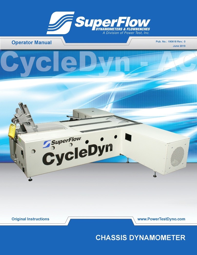
SuperFlow AutoDyn User manual

ii
Please keep this manual for future reference.
This manual is intended to assist operating personnel in becoming familiar with the product and as guidance
in ordering necessary parts inclusive of Axiline's warranty requirements. Maximum operating eciency and
life of any Axiline Precision Product will be attained through complete understanding of the instructions and
recommendations contained within this manual.
Services performed beyond preventive
maintenance by personnel other than Axiline
Service Technicians on any Axiline products
during the warranty period may void the warranty.
!WARNING
When available, please include the model
number and serial number of the product in any
correspondence.
IMPORTANT
Copyright 2018 by SuperFlow, a division of Power Test, Inc. All rights reserved. No part of this publication may
be reproduced, transcribed, or translated by any means without the prior written permission of SuperFlow,
N60 W22700 Silver Spring Drive, Sussex, WI 53089 USA.
No part of the software or rmware provided with this product may be upgraded, modied, or changed by any
means without the prior written permission of SuperFlow.
Power Test, PowerNet, SuperFlow, WinDyn, ProFilter, SF902, XConsole, XDyno, XCart, NSCR, CycleDyn,
AutoDyn, FlowCom, SuperBench, ProExport, SF-110/120/260/450/600/750, SF-1020, SF1200, ProBench,
SuperBench, TD-1200, TDAC, AIDCO,Axiline, TCRS, Hicklin, Racer’s Pack, and SuperShifter are trademarks
of Power Test, Inc. Other trademarks and trade names may be used in this document that refer to the entities
claiming the marks and names or their products. Power Test, Inc. does not hold any proprietary interest in
trademarks or trade names other than its own.
Trademark Notices

Table of Contents
1 General Information
2 System Overview
3 Packaging and Handling
4 Test Area Requirements
5 Installation
6 System Operation
7 Handheld Controller
8 Theory of Testing
9 Description of the Configuration File
11 Control Modes
20 Calibration and Maintenance
Appendix A General Testing Information
Appendix B Fundamental Concepts to Repeatability
WinDyn – Users Guide

AutoDyn Operators Manual
Section 1 - Page 4 AutoDyn Cover.fm

1
General
Information

Safety Warnings
SuperFlow Technologies Group 1-3
1.1 Safety Warnings
WARNING: To ensure safe operation, this equipment must only be operated according to
the instructions in the SuperFlow AutoDyn Operator’s Manual. It is also essential that this
equipment is installed, maintained, and operated according to local safety requirements.
Any person instructed to carry out installation, maintenance or repair of the equipment must read
and understand the AutoDyn Operator Manual and in particular the technical safety instructions.
Any users of this equipment must operate only the controls of the equipment. Only qualified
personnel should remove exterior panels and service equipment.
1.1.1 Dangers Due to Non-observance of Safety
Instructions
• Carbon monoxide poisoning
• Hearing damage due to high noise levels
• Electrical shock
• Exposure to rotating parts
1.2 General Safety Procedures
CAUTION: Electronic controls contain static-sensitive parts. Observe the following precautions to
prevent damage to these parts.
•Discharge body static before handling the control (with power to the control turned off, contact a
grounded surface and maintain contact while handling the control).
•Avoid all plastic, vinyl, and Styrofoam (except antistatic versions) around Printed Circuit Boards
(PCBs).
•Do not touch the components or conductors on a PCB with your hands or with conductive
devices.
CAUTION: To prevent damage to a control system that uses an alternator or battery-charging
device, make sure the charging device is turned off before disconnecting the battery from the
system.
Always follow basic safety precautions when using this product to reduce risk of injury and/or
damage to equipment.
• Only authorized personnel trained in the operation of the dynamometer should have access
to the equipment.
• Read and understand all instructions in the user guides.
• Use only the proper electrical sources as prescribed in the installation guide. Ensure circuit
breakers are easily accessible and have the proper rating.
• Observe all warnings and instructions marked on the product.
• Ensure proper ventilation of exhaust gases from the vicinity of the dynamometer

Safety
1-4 AutoDyn Chassis Dynamometer Operator Manual
• Provide fire extinguishers that are rated for electrical and oils.
• Provide adequate lighting in the test cell and at the operators console.
• Always wear proper protective clothing and eye/ear protection.
• Refer all service questions to qualified personnel.
• Do not remove any safety guards while the machine is in operation and be sure the safety
guards are correctly mounted before operating the device.
• Disconnect the external power switch before opening the rear panel of the device.
• Replace the power cable if it is damaged.
• Keep the air inlet grids free of dust or dirt.
• Keep loose material away from the inlet and exhaust air ducts.
• Do not store flammable materials in the vicinity of the dynamometer.
• Keep all personnel, flammable items, and sensitive objects away from any rotating object
that can throw debris radially outward.
1.3 Room Requirements
When working in or building a test cell:
• Follow all local construction codes.
• Install a Carbon Monoxide (CO) detector in the test cell.
• Provide fire extinguishers that are rated for gasoline and oils.
• Provide adequate lighting in the test cell and at the operators console.
• Provide a means outside the test cell to turn off the ventilation fans and electrical circuits.
1.4 Noise Levels
SuperFlow Technologies Group always recommends ear protection when operating any product.
Warning Signs of Hazardous Noise1
• You must raise your voice to be heard.
• You cannot hear someone two feet away from you.
• Speech around you sounds muffled or dull after leaving a noise area.
• You have pain or ringing on your ears (tinnitus) after exposure to noise.
1. Information in this section was adapted from “Noise and Hearing Loss,” American Speech-Language-Hearing
Association, 1997–2007, http://www.asha.org/public/hearing/disorders/noise.htm, 2007.

Carbon Monoxide Warnings
SuperFlow Technologies Group 1-5
Hazardous Noise
Both the amount of noise and the duration of exposure determine the amount of damage to
hearing. Noise levels are measured in decibels (dB). The higher the decibel level, the louder the
noise. Hair cells of the inner ear and the hearing nerve can be damaged by an intense brief impulse
(such as an explosion) or by continuous or repeated exposure to noise.
For sound levels of 85 decibels (dB) or above, use hearing protection. Please follow all safety
standards when operating this or any equipment.
1.5 Carbon Monoxide Warnings
When operating fuel-generated equipment in enclosed areas, take the following precautions to
protect you and your employees against carbon monoxide exposure.
What is carbon monoxide?1
Carbon monoxide (CO) is a poisonous, colorless, odorless, and tasteless gas. Although it has no
detectable odor, CO is often mixed with other gases that do have an odor; therefore, you can
inhale carbon monoxide right along with gases you can smell and not even know that CO is
present.
CO is a common industrial hazard resulting from the incomplete burning of natural gas and any
other material containing carbon such as gasoline, kerosene, oil, propane, coal, or wood. One of
the most common sources of exposure in the workplace is the internal combustion engine.
How does CO harm you?
Carbon monoxide is harmful when breathed because it displaces oxygen in the blood and
deprives the heart, brain, and other vital organs of oxygen. Large amounts of CO can overtake you
in minutes without warning—causing you to lose consciousness and suffocate.
Besides tightness across the chest, initial symptoms of CO poisoning may include headache,
fatigue, dizziness, drowsiness, or nausea. Sudden chest pain may occur in people with angina.
During prolonged or high exposures, symptoms may worsen and include vomiting, confusion,
and collapse in addition to loss of consciousness and muscle weakness. Symptoms vary widely
from person to person. CO poisoning may occur sooner in those most susceptible: young children,
elderly people, people with lung or heart disease, people at high altitudes, or those who already
have elevated CO blood levels such as smokers. CO poisoning poses a special risk to fetuses.
Acute poisoning may result in permanent damage to the parts of your body.
1. Information in this section was adapted from the “OSHA Fact Sheet,” U.S. Department of Labor, Occupational Safety
and Health Administration, 2002, http://www.osha.gov/OshDoc/data_General_Facts/carbonmonoxide-
factsheet.pdf, 2007.

Safety
1-6 AutoDyn Chassis Dynamometer Operator Manual
How can employers help prevent CO poisoning?
To reduce the chances of CO poisoning in your workplace:
• Install an effective ventilation system that will remove CO from work areas.
• Maintain equipment and appliances that can produce CO to ensure they are in good
working order, promote their safe operation, and reduce CO formation.
• Consider switching from gasoline-powered equipment to equipment powered by
electricity, batteries, or compressed air if it can be used safely.
• Prohibit the use of gasoline-powered engines or tools in poorly ventilated areas.
• Provide personal CO monitors with audible alarms if potential exposure to CO exists.
• Test air regularly in areas where CO may be present, including confined spaces.
• Install CO monitors with audible alarms.
• Use a full-face piece, pressure-demand, Self-Contained Breathing Apparatus (SCBA)
certified by the National Institute for Occupational Safety and Health (NIOSH) or a
combination full-face piece, pressure demand supplied-air respirator with auxiliary self-
contained air supply in areas with high CO concentrations (those immediately dangerous to
life and health atmospheres).
• Use respirators with appropriate canisters for short periods under certain circumstances
where CO levels are not exceedingly high.
• Educate workers about the sources and conditions that may result in CO poisoning as well
as the symptoms and control of CO exposure.
• In addition, if your employees are working in confined spaces where the presence of CO is
suspected, you must ensure that workers test for oxygen sufficiency before entering.
What can employees do to help prevent CO poisoning?
To reduce the chances of CO poisoning in the workplace, employees should:
• Report any situation to your employer that might cause CO to accumulate.
• Be alert to ventilation problems—especially in enclosed areas where gases of burning fuels
may be released.
• Report promptly complaints of dizziness, drowsiness, or nausea.
• Avoid overexertion if you suspect CO poisoning, and leave the contaminated area.
• Tell your doctor that you may have been exposed to CO if you get sick.
• Avoid the use of gas-powered engines, such as those in powered washers as well as heaters
and forklifts, while working in enclosed spaces.
What are the OSHA standards for CO exposure?
The OSHA PEL is 50 parts per million (ppm). OSHA standards prohibit worker exposure to more
than 50 parts of the gas per million parts of air averaged during an 8-hour time period.
For more information on carbon monoxide, visit the OSHA Web site at http://www.osha.gov.

SYSTEM OVERVIEW
Section 2 - Page 1
2
System Overview

2. System Overview
2.1. Purpose ..................................................................................................... 5
2.2. Components .............................................................................................. 6
2.3. Frame Assembly ........................................................................................ 6
2.4. Power Absorber Assemblies ..................................................................... 7
2.4.1. Single Eddy Current absorber module ................................................................7
2.4.2. Dual Eddy Current absorber module ................................................................... 8
2.5. Sensor Box ................................................................................................ 9
2.6. Specifications .......................................................................................... 10

SYSTEM OVERVIEW
Section 2 - Page 5
2.1. Purpose
The AutoDyn vehicle dynamometer is a chassis dynamometer
(“rolling road”) designed to allow testing of passenger cars,
sport utility vehicles, light trucks, and similar vehicles within
the workshop environment.
Typical applications include:
• Performance testing
• Diagnostic testing
• Education
• Vehicle certification
• Research and development
Testing on a dynamometer reduces road testing liability,
improves measurement accuracy, and enhances productivity.
The AutoDyn is a scalable system which can be customized to
fit your requirements.
AutoDyn with Corvette

Manual
AutoDyn
Section 2 - Page 6 AutoDyn manual 1174 Sect ion 2. PM7, 5/2004
2.2. Components
The AutoDyn dynamometer consists of three major components. These
are the frame assembly, the sensor box, and the absorber module (if
applicable).
A more detailed description of each of these components follows.
2.3. Frame Assembly
The frame contains the rolls, roll shaft or axle, air-actuated roll
brakes, and a tachometer gear with magnetic pick-up.
The frame is boxed for improved stiffness and to achieve the most
compact design. The absorber is driven off the axle differential pinion
gear via a drive-shaft. The axle is mounted in trunnion bearings and a
load cell connects the differential to the frame.All parasitic losses are
measured by the load cell, except the windage (aerodynamic losses) of
the rolls. The windage is measured at the factory and compensated in
the software. The rolls are mounted on the axle wheel flanges and can
be removed after unbolting end plates on both sides of the frame.
The truck axle differential allows the use of different axle ratios for
different applications. The standard ratios are 2.79:1 for Eddy Current
absorbers. This selection is based on a maximum design speed of 200
mph. Other axle ratios result in different speed and power characteristics
of the dynamometer.
Therolls havea nominal diameter of 42” (106.7 cm)and are28” (71.1cm)
wide. They are spaced 28” (71.1 cm) apart. The inertia of the rolls is
measured by SuperFlow to provide an exact calculation of power when
the roll is accelerated. This inertia value is stored in the sensor box
electronics.
A magnetic pick-up detects the teeth on the tachometer gear. This
frequency is then converted to roll speed via the CPU printed circuit
card and the system software. The magnetic pick-up also creates a
signal that interlocks the roll brakes and lift or ramp commands (if
applicable) while the roll is rotating.
The roll brakes consist of a hydraulic disk brake installed on the
differential pinion shaft. The brakes are actuated by an air solenoid,
which must be supplied with 100 psi (690 kPa) air pressure.
An electrical interface box is mounted on the dynamometer frame. On
the dynamometer side, this interface box is wired to the load cell, the
magnetic pick-up, the roll lock solenoid, and the absorber. The interface
box groups all dynamometer data and control signals for connection to
the sensor box. The sensor box is connected with a single cable.
For above-ground installations, the dynamometer frame can be
equipped with restraint bars, which offer convenient tie-down points for
one end of the vehicle. For pit installations, tie-down points should be
embedded in the concrete floor slab.

SYSTEM OVERVIEW
Section 2 - Page 7
Place the dynamometer frame assembly so that it is on a level surface.
Reducing any twisting stress on the main frame will enhance overall
durability and improve measurement accuracy. Jack feet are provided for
easy alignment.
Differential oil cooler (optional)
On some models, a differential oil cooler may be supplied for
endurance testing. This cooler consists of a thermostatically
controlled oil-to-water heat exchanger, a circulation pump, and
an oil filter. Thermocouple temperature measurements are
provided and quick connect couplings are used.
2.4. Power Absorber Assemblies
The (optional) absorber packages are used to simulate addi-
tional inertia, or to measure power at a constant speed. The
AutoDyn can be equipped with two different absorber packages. Both
are mounted in a specific module, which attaches to the front of the
dynamometer frame. The absorbers are connected to the truck axle
differential (and thus the rolls) via a short drive-shaft. The addition of
an absorber to the system allows speed or torque control. This feature
allows the user to run constant speed, constant torque, or controlled
acceleration tests.
The load cell measures the total force applied by the vehicle and sends
an analog voltage to the CPU for conversion and measurement. Because
the axle is trunnion-mounted, all torque reaction forces are measured by
the load cell mounted on the differential and there is no need for
trunnion-mounting the absorber. This improves the accuracy of torque
measurement and makes it independent of differential oil temperature or
absorber alignment. The force measured is only as accurate as the
calibration that must be performed on the unit. If the calibration is off by
five percent, then the measurement will be off by five percent as well.
The axle has mounting points for a torque calibration arm. The calibra-
tion arm is supplied with the dynamometer.
Both types of absorber modules available for the AutoDyn are de-
scribed below.
2.4.1. Single Eddy Current absorber module
A module with a single, air-cooled eddy current absorber is attached to
the dynamometer. The load is applied by generating an electric field in
which rotors of magnetic material turn. This results in an electro-
magnetic resistance to rotation, which can be controlled by varying the
current in the coils generating the electric field.
Eddy Current absorbers achieve fast response, excellent stability, and
high torque at low speeds. An air-cooled eddy current absorber must
dissipate all power into the air circulating through the rotors. For high
power applications, the rotors will heat up rapidly which will reduce
their power capability. For this reason, an air-cooled eddy current

Manual
AutoDyn
Section 2 - Page 8 AutoDyn manual 1174 Sect ion 2. PM7, 5/2004
absorber is suitable for short high-power runs with sufficient cooling
time between runs, or for low power testing over longer periods of time.
The main advantage of the air-cooled eddy current absorber is the ease
of installation: no external cooling systems are required.
2.4.2. Dual Eddy Current absorber module
A module containing two identical eddy current absorbers is attached to
the dynamometer. This module operates in exactly the same way as the
single eddy current absorber module, except it almost doubles the
power absorption capacity of the dynamometer.

SYSTEM OVERVIEW
Section 2 - Page 9
2.5. Sensor Box
The sensor box contains the CPU (Central Processing Unit) printed
circuit card, thermocouple printed circuit card, pres-sure printed circuit
card, and the user interface printed circuit card. Data that is recorded
and displayed by the dynamometer is measured by these printed circuit
cards. The system measures the Engine Speed, and Roll Speed as
frequencies, and then converts these frequencies to digital information.
The Load Cell (with absorber models) measures the torque produced by
the vehicle as an analog voltage, and converts that voltage to digital
information. The pressures and thermocouples are also measured as
analog voltages, and converted to digital information.Abarometric
pressure transducer is located inside of the sensor box. This transducer
produces an analog voltage that is converted to digital
information.There are also “Specifications” that are not measured, but
actually entered by the user. Specifications configure the system for
each vehicle. These are used for calculations of some of the data
displayed by the system.
From 2 to 8 LCD displays are available, depending on the model
configuration.
Pro Sensor Box

Manual
AutoDyn
Section 2 - Page 10 AutoDyn manual 1174 Sect ion 2. PM7, 5/2004
2.6. Specifications
TheAutoDyn dynamometer uses SuperFlow’s New Generation Elec-
tronics (NGE) for state-of-the-art data acquisition and control perfor-
mance. Two levels of NGE are used:
Some older models use the SF-1942/2060 board-set
Technical specifications for each board-set are listed below.

SYSTEM OVERVIEW
Section 2 - Page 11
NGE Data Acquisition and Control System Specifications
SF-2620 board based systems
Processor • Two MC 68332 microcontroller
• Clock speed 25 MHz
On-board memory
• 1MB Operating System Flash ROM
• 1 MB of battery backed SRAM.
1 MB non-batery-backed SRAM
Network communication
• IEEE 802.3 MAC Network controller with 10-Base-2 and10 Base-
T Ethernet interface
• NetBEUI protocol
• 16k Dual port RAM interface
Data Acquisition
8-channel, 12 bit serial interfaced Analog to Digital Converter
(ADC) expandable to hundreds of channels via on-board
multiplexing
Data acquisition rate
• Base rate: 1200 Hz
• 5 channels at 150Hz
• 8 channels at 60 Hz
• 2 groups of 8-128 expansion channels each measured at 1/8 of
the base rate
• frequency channels at 200 Hz
Data filtering • User-selected
• 8 levels of 4 pole filters
I/O • On-board barometric pressure transducer with signal
conditioning
• Sensor inputs
- analog: up to 269 analog voltage channels (WinDyn V
1.12 limit to 70 channels)
- frequency: up to 4 mag/TTL frequency channels (WinDyn
V 1.12 limit to 6 channels)
- inductive, capacitive, or coil primary spark pick-up signal
circuit
- photo tach input circuit
• Other input/outputs
-6 RS232, RS422, RS485, J1708 serial ports

Manual
AutoDyn
Section 2 - Page 12 AutoDyn manual 1174 Sect ion 2. PM7, 5/2004
- 8 digital inputs
• Outputs
- 8 relay-capable digital outputs
• LCD Display drivers
- serial port for up to 4 LCD boards with 2 six-character LCD’s
each, daisy-chained
• 4 Controller interfaces, Steppers,EC, 4-20 ma, 0-10VDC
- 1 RS-232 serial port
- 8 TPU lines
- 3 analog feedback signals
Safeties (not implemented on standard Auto Dyn systems)
- Emergency Stop command (EMS) scanned at 150 Hz
- Loop of series-connected, normally closed switches for external panic
buttons
- Internal loop for panic buttons on SF equipment
-4 digital inputsconfigurable for Normally Open (NO),Normally Closed
(NC),or TTLinput
- one DPDT relay output supplies the EMS signal to external devices
Power supply - Type: ATX
- 115/230 VAC, 6/3 Amps
- 50/60 Hz
SF-1942/2060 board-set based systems on some older systems
Processors • A Processor (1942 board):
- MC 68332 microcontroller
- On-board memory:
256k SuperOS ROM
512x16 serial EEPROM
512 k FLASH for application program
256 k battery backed SRAM
up to 8 MB 72-pin SIMM DRAM
• B Processor (1942 board):
- MC 68332 microcontroller

SYSTEM OVERVIEW
Section 2 - Page 13
- On-board memory:
256k system ROM
256 k battery backed SRAM
512k FLASH
• Clock speed 16.78 MHz
• 16k Dual port RAM interface
Network communication
• IEEE 802.3 MAC Network controller with 10-Base-2 and 10-
Base-T Ethernet interface
• NetBEUI protocol
• 16k Dual port RAM interface
Data acquisition
• 6 programmable gain amplifiers
• 8-channel, 12 bit serial interfaced Analog to Digital Con-
verter (ADC)
Data acquisition rate
• Base rate: 1 kHz
• 5 channels at 1 kHz
• 8 channels at 312 Hz
• 2 groups of 8-128 expansion channels each measured at 1/
8 – 1/128 of the base rate
• frequency channels at 200 Hz
Data filtering • User-selected
• 8 filter levels
I/O • On-board barometric pressure transducer with signal
conditioning
• Sensor inputs
- analog: up to 269 analog voltage channels (WinDyn V
1.12 limit to 70 channels)
- frequency: up to 11 mag/TTL frequency channels
(WinDyn V 1.12 limit to 6 channels)
- inductive, capacitive, or coil primary spark pick-up signal
circuit
- photo tach input circuit
- input for 2-channel quadrature encoder or additional TTL
frequency channel
• Other inputs
- 4 RS232 serial ports
- 6 digital inputs
Table of contents
Other SuperFlow Measuring Instrument manuals