Nobili BNE Series Specification sheet

Shredder
type: BNE
04.09.2009

AGRICULTURAL MACHINERY MANUFACTURERS
2
04.09.2009
CORRECT USE OF THE MACHINE
WARNING: Before using the machine it is necessary to check the following points:
1°) The machine should be included in the weight and overall dimension limits mentioned in the
tractor use manual, regarding the equipped tools
2°) In case of rear coupling, with the machine raised from the ground, check that on the tractor front
axle (steering) there is a residual weight not lower than 20% of total weight.
EXAMPLE
Total weight = Tractor weight + Machine weight = 2500 Kg + 800 Kg = 3300 Kg
Residual weight on the steering axle = 20% di 3300 Kg = 660 Kg
IT IS NOT ALLOWED:
• Working on stony or uneven grounds.
• Transporting persons, animals, or things.
• Towing cars or equipment.
• Working near houses or roads.
• Fitting other equipment which may change the machine's characteristics.
• Machine tools must NEVER touch the ground.
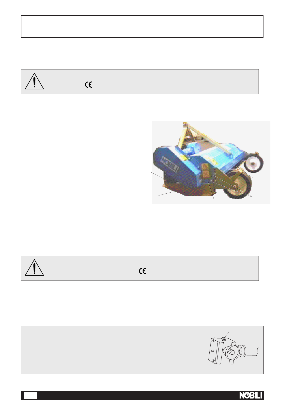
INTENDED USE
NOBILI S.p.A. - Agricultural Machinery Manufactures - wishes first of all to thank you for the wise choice you have
made in purchasing one of its machines, whilst assuring you that the maximum efforts have been put into making
the machine as advanced and practical as possible.
In order to get the best use out of the machine and prolong its working life, NOBILI S.p.A. has decided to give a
few practical hints to help you use it to its full potential and to help you avoid those problems that are due, in the
majority of cases, not to manufacturing defects, but mainly to negligence and carelessness.
NOBILI BNE multivalent shredders have been designed for the following activities: care of grassland and public
parks, shredding of thin wood, vine sarments, and potato leaves.
Machine tools - blades or rams - must NEVER touch the ground.
The correct use of the machine includes:
- following carefully manufacture's instructions regarding use, maintenance and care of your machine.
- using original spare parts only, as well as original or approved units and accessories.
The use of the machine, its maintenance and repairs are reserved to specialized people, who are familiar with the
technical data and features of these machines.
WARNING! THIS SYMBOL, USED THROUGHOUT THIS MANUAL, MARKS
INSTRUCTIONS THAT MAY AFFECT YOUR SAFETY, OTHER PEOPLE'S SAFETY, AND
THE EFFICIENT WORKING OF THE MACHINE. ALWAYS FOLLOW THE SAFETY
INSTRUCTIONS SCRUPULOUSLY.

AGRICULTURAL MACHINERY MANUFACTURERS 3
04.09.2009
USER'S MANUAL No. AO 917
SHREDDERS: BNE 100 - 120 - 150 - 180 - 210
CONTENTS
INTENDED USE ....................................................................................................................... Page 2
MARKS AND MACHINE IDENTIFICATION ............................................................................ Page 4
Declaration of conformity .......................................................................................................... Page 4
Characteristics and machine identification ............................................................................... Page 5
Decals regarding: Safety- Use - Maintenance .......................................................................... Page 6-7-8
SAFETY PRECAUTIONS......................................................................................................... Page 9
Hoisting the machine and transport .......................................................................................... Page10
Dangerous areas ...................................................................................................................... Page 11
Recommandations for use ........................................................................................................ Page 12
Checking tools and corresponding locking pins ....................................................................... Page 13
STARTING AND STOPPING THE MACHINE
INFORMATION REGARDING USE AND ADJUSTMENT
..........................................................
Page 14
Assembly of skids, roller, wheels and corresponding guards................................................... Page 14
Coupling to the tractor .............................................................................................................. Page 15
Connecting the propeller shaft.................................................................................................. Page 16
Working height adjustment ....................................................................................................... Page 17
How to displace fixed drawbar .................................................................................................. Page 18
Parking position ........................................................................................................................ Page 19
INFORMATION REGARDING ACOUSTIC PRESSURE ......................................................... Page 20
Air noise emitted ....................................................................................................................... Page 20
INFORMATION REGARDING MAINTENANCE ...................................................................... Page 21
Lubrication ................................................................................................................................ Page 21
Belt tension ............................................................................................................................... Page 22
Tool replacement and balancing ............................................................................................... Page 23
ACCESSORIES: DRAWBARS WITH LATERAL SHIFTING ................................................... Page 24
Assembly and adjustments of drawbars with lateral shifting .................................................... Page 24
Warning signs ........................................................................................................................... Page 25
Overall dimensions ................................................................................................................... Page 25
TROUBLESHOOTING.............................................................................................................. Page 26
WARRANTY ............................................................................................................................. Page 27

AGRICULTURAL MACHINERY MANUFACTURERS
4
04.09.2009
F A C - S I M I L E
S.p.A.
Via Circonvallazione Sud, 46 40062 MOLINELLA (BO)
Declaration de conformité
à la directive "machines"
(Directive 89/392/CEE modifiée)
et aux réglementations prises pour sa transposition
Le fabricant:
EC declaration of conformity
(conforming to directive
89/392/EEC amended)
The manufacturer:
EG-Konformitätserklärung
(entsprechend der EG-Richtlinie
89/392/EWG und deren Änderungen).
Der Hersteller:
Dichiarazione di Conformità
ai sensi della direttiva CEE 89/392
e successive modificazioni.
Il costruttore:
declares that the product
described hereafter:
déclare que la machine
désignée ci-dessous
:
erklärt in alleiniger
Verantwortung, daß das
Produkt:
dichiara che la macchina
sotto descritta:
Tipo - Type
Type - Typ:
......................................
N°- N°
No - Nr.:
......................................
.
In caso di vendita della macchina, la presente dichiarazione deve essere consegnata all'acquirente.
En cas de revente de la machine, la présente déclaration de conformité est a remettre à l'acheteur.
In the case of resale of the machine, this declaration of conformity is to be passed on to the buyer.
Bei Weiterverkauf dieser Maschine ist diese Konformitätserklärung dem Käufer zu übergeben.
Molinella (BO) Li-Le-Date-Den:................
-est conforme aux dispositions de la directive
européenne
89/392/CEE
modifiée ainsi qu'à celles de la directive:
86/188/CEE.
-est conforme aux dispositions des normes
européennes harmonisées suivantes:
EN 294 EN
349
-est égalment conforme aux normes nationales et
aux dispositions techniques suivantes:
auf das sich diese Erklärung bezieht, den
einschlägigen grundlegenden Scherheits- und
Gsundheitsanforderungen der EG-Richtlinie
89/392/EWG und deren Änderungen, sowie den
Anforderungen der einschlägigen EG-Richtlinie
86/188/EWG entspricht.
Zur sachgerechten Umsetzung der in den
EG-Richtlinien genannten Sicherheits- und
Gesundheitsanforderungen wurden die
harmonisierten Normen:
EN 294 EN 349
sowie die nationalen Normen und techischen
Spezifikationen:
herangezogen.
to which this declaration applies, conforms to the
essential health and safety requirements of
European Council Directive 89/392 CEE amended
and conforms also to the requirements of Directive
86/188/EEC.
-to conform to these essential health and safety
requirements, the provisions of following
harmonized standards were particularly considered:
EN 294 EN 349
-the provision of following national standards and
specifications were also considered:
è conforme ai Requisiti essenziali di Sicurezza e di
Tutela della Salute di cui alla Direttiva CEE 89/392 e
sue successive modificazioni, nonché ai Requisiti di
cui alle seguenti Direttive CEE:
86 /188 /CEE
Per la verifica della Conformità di cui alle Direttive
sopra menzionate, sono state consultate le seguenti:
Norme Armonizzate:
EN 294 EN 349
Norme e specifiche Tecniche:
Responsabile della Sicurezza -- Responsable Sécurité et Homologations -- Safety Officer--Beauftragter für Gerätesicherheit
.
.............................................................
Barilani Andrea
TRINCIA
BROYEUR
SHREDDER
MULCHGERÄT
DECLARATION OF CONFORMITY

AGRICULTURAL MACHINERY MANUFACTURERS 5
04.09.2009
540 r.p.m.
Machine power input:
BNE 100 11 Kw 15 HP
BNE 120 15 Kw 20 HP
BNE 150 18 Kw 25 HP
BNE 180 22 Kw 30 HP
BNE 210 29 Kw 40 HP
TECHNICAL CHARACTERISTICS
BNE 1
TECHNICAL CHARACTERISTICS BNE 100 BNE 120 BNE 150 BNE 180 BNE 210
Tractor coupling Range 1°1°1°1°1°
P.T.O. speed r.p.m. 540 540 540 540 540
Required power Kw 11 15 18 22 29
Transport position Transversal
Max. transport width mm 1245 1445 1730 2015 2300
Weight for standard version Kg 180 190 210 240 270
Working position central or on the right -- -- 370 370 370
Working components Blades Y N°28 32 40 48 56
Vanes N°14 16 20 24 28
Rams N°14 16 20 24 28
Swivelling blades N°28 32 40 48 56
Working width mm 978* 1177* 1460* 1745* 2030*
Cutting rim speed m\sec 48,5 48,5 47,9 47,9 47,9
Rotor speed r.p.m. 2230 2230 2207 2207 2207
Main drive Bevel Gear Pair
Secondary drive Belt type: B 46 Belt type: SPBX
n°3 belts n°3 belts
Cutting height adjustment Manual
Lateral shifting adjustment Manual or hydraulic
ACCESSORIES
Sliding drawbar, hydraulic No No Yes Yes Yes
Parallelogram drawbar, hydraulic No No Yes Yes Yes
Rear wheels N°22222
Rear roller Yes Yes Yes Yes Yes
* Dimension with rams 06
MARCATURA E RICONOSCIMENTO DELLA MACCHINA
TARGHETTA FISSATA AL TELAIO (Vedi Pag. 6)
SERIE E TIPO
MACCHINA
NUMERO DI
MATRICOLA
ANNO DI
COSTRUZIONE
MASSA IN
VERSIONE
COMPLETA DI
ACCESSORI
NOME ED INDIRIZZO DEL COSTRUTTORE
TRINCE
BROYEURS
TRITURATOR
MULCHER
LUBRIC. ACONSEJADOS - RECOMMENDED LUBRICANTS
EMPFOHLENE OELE/FETTE - LUBRIFIANTS CONSEILLES
LUBRIFICANTI CONSIGLIATI
Mod.
Num.
Data
Massa Kg :
:
:
:
BLASIA 460
(ISO 460)
MU / EP2
SUPERTRACTOR
UNIVERSAL
COSTRUZIONI
MECCANICHE
PER L’AGRICOLTURA
R

AGRICULTURAL MACHINERY MANUFACTURERS
6
04.09.2009
ADHESIVE LABELS REGARDING SAFETY
AND PROPER OPERATION
7
2
A
B
CB
11
8
4
5
10
12
1
1
4
13 CB
CR
CR
A ) Machine identification metal plate.
B ) Type and model of the machine
CB) White reflectors
CR) Red reflectors
Safety labels are located on the machine according to the pictures below.
Decals have been designed for your safety and for other people's safety.
The machine's owner or the person in charge must be sure the operator has read the Instruction Manual carefully.
Keep decals in good conditions and replace the damaged ones.
The adhesive labels N°6 - 7 - 12 - 14 are not applied on the BNE series machine.

AGRICULTURAL MACHINERY MANUFACTURERS 7
04.09.2009
READ THE INSTRUCTION
MANUAL BEFORE
STARTING THE MACHINE
DANGER!
THROWN OBJECTS.
STAND OFF.
DO NOT WORK NEAR
BUILDINGS OR ROADS
1
3
GREASE EVERY 4 WORKING HOURS
GREASE EVERY 50 WORKING HOURS
MACHINE SET FOR
POWER INPUT AT 1000 r.p.m.
6
5
7
MACHINE SET FOR
POWER INPUT AT 540 r.p.m.
DO NOT REMOVE
GUARDS UNTIL ALL
ROTATING PARTS
ARE IDLE
TURN OFF THE
TRACTOR ENGINE AND
TAKE THE KEY OFF
BEFORE SERVICING
OR ADJUSTING THE
MACHINE
ADHESIVE LABELS
2
4
8
0018646 0018642
0018650 0018645
50 h.

AGRICULTURAL MACHINERY MANUFACTURERS
8
04.09.2009
ADHESIVE LABELS
10 11
12
LIFT THE
MACHINE FROM
THE GROUND
BEFORE GOING
INTO REVERSE
OR TURNING
SHARPLY.
14
15
INDICATION OF THE HOOKING
POINTS FOR LIFTING THE
MACHINE.
13
0018658

AGRICULTURAL MACHINERY MANUFACTURERS 9
04.09.2009
SAFETY PRECAUTIONS
MANY INDUSTRIAL INJURIES ARE DUE TO THE LACK OF
RESPECT OF THE MOST ELEMENTARY SAFETY PRECAUTIONS.
• Thus it is necessary that whoever needs to work or to carry out the maintenance of the machine,
knows the safety precautions described in the manual or on the decals.
• Before any cleaning or maintenance operations, it is necessary to lay the machine horizontally on the
ground or on strong supports, stop the tractor engine and remove the propeller shaft.
• Before beginning work, check: tightening of bolts, integrity and efficiency of guards, right position of
safety pins.
• Be sure that the tractor meets the CHARACTERISTICS REQUIRED BY THE MACHINE USED.
• Keep persons and animals away from the machine before its starting.
• Do not leave the machine running without surveillance.
• Do not wear clothes which can get entangled.
• Do not transport persons or animals on the machines.
• Check that the PROPELLER SHAFT IS MARKED AND THAT, DURING ASSEMBLY,THE GUARDS
ARE PROTECTED AGAINST ROTATION with the appropriate chains.
• Be particularly careful when you work on cat’s backs or ditches.
• Be particularly careful when you work on cat’s backs or ditches.
The uneven ground can make the guards temporarily inefficient and allow the projection of stones or
fragments in a wide range (See page 11).
• Be particularly prudent during the road-transport of the machine.
The user must be sure that the transport complies with the highway Code of the Country where it is
CARRIED OUT.

AGRICULTURAL MACHINERY MANUFACTURERS
10
04.09.2009
USE HOISTING EQUIPMENT ACCORDING TO THE RULES IN FORCE AND RIGHT
FOR THE MACHINE WEIGHT.
WARNING: BE CAREFUL AS ACCESSORIES AFFECT MACHINE BALANCE.
NEVER LIFT UNBALANCED LOADS.
HOISTING THE MACHINE
Available hitch points:
1) ø 20 holes, on the machine sides
2) hitch pin, 3rd point
ENIHCAM THGIEW
gK
001ENB 081
021ENB 091
051ENB 012
081ENB 042
012ENB 072

AGRICULTURAL MACHINERY MANUFACTURERS 11
04.09.2009
DANGEROUS AREAS
Before shredding: Keep all persons and animals away from the machine
danger zone. This zone is defined by a radius (R) of 50 m (164') around the
working line of the machine.
The use of the machine hood must be only destined to maintenance
operations.
Before maintaining the machine, stop the tractor motor, turn off the engine,
remove ignition key and wait until all moving parts have come to a
complete stop.
It is strictly forbidden to leave the hood open when the machine is operating
and its parts are moving.
The misuse of the machine may cause involuntary projection of stones and
other foreign objects, and consequently damages to persons, things and
animals.

AGRICULTURAL MACHINERY MANUFACTURERS
12
04.09.2009
RECOMMENDATIONS FOR USE
ALWAYS STOP THE TRACTOR ENGINE BEFORE CARRYING OUT ANY WORK OF
ADJUSTMENT OR CLEANING ON THE MACHINE.
BEFORE STARTING THE ADVANCING OF THE MACHINE, WAIT THAT THE ROTOR REACHES THE R.P.M.
WORK ONLY ON STRAIGHT LINE, LIFT THE MACHINE FROM THE GROUND BEFORE CHANGING
DIRECTION.
DO NOT ACTIVATE THE SIDE DISPLACEMENT WITHOUT LIFTING THE MACHINE.
IF DURING THE LIFTING FROM THE GROUND, THE JOINTS OF THE PROPELLER SHAFT ARE BENT TO
MORE THAN 40°(STILL P.T.O.) REMOVE THE SHAFT OF THE TRACTOR P.T.O.
DURING WORK, BLADES OR RAMS SHOULD NOT TOUCH THE GROUND.
DAILY CHECK THE WEAR OF BLADES OR RAMS.
IN CASE OF IRREGULAR CONSUMPTIONS OR BREAKS, IMMEDIATELY SUBSTITUTE THE DAMAGED
PARTS. USE ONLY ORIGINAL SPARE PARTS.
AFTER THE FIRST HOURS OF WORK (3 HOURS) CHECK THETENSION OF THE BELTS, DAILY CONTROL
THE TIGHTENING OF ALL NUTS AND BOLTS AND THE TENSION OF THE BELTS.
VERIFY SPECIALLY THE TIGHTENING OF BLADE BOLTS (See page 13).
CHECK THAT THE SAFETY CHAINS OF PINS AND THE ANTIROTATION CHAINS OF THE PROPELLER
SHAFT GUARDS ARE INTACT AND COUPLED UP.
CLEAN, WASH, GREASE THE INSIDE AND OUTSIDE OF THE MACHINE AT REGULAR INTERVALS.
SPECIALLY REMOVE THE MATERIAL SETTLED ON THE ROTOR AND BLADE SUPPORTS.
BEFORE A LONG PERIOD OF INACTIVITY THE MACHINE SHOULD BE CLEANED AND GREASED. PUT
IN A PLACE PROTECTED FROM BAD WEATHER.
THE USER IS COMPLETELY RESPONSIBLE OF ROAD-TRANSPORT.HE MUST CHECK THE COMPLIANCE
WITH THE HIGHWAY CODE IN FORCE IN HIS COUNTRY.
IF ATRACTOR WITHOUT SOUNDPROOF AND PRESSURIZED CABIN IS USED, IT IS NECESSARYTHAT
THE OPERATOR USES INDIVIDUAL PROTECTION SYSTEMS:
1) PROTECTION EARPIECES FOR NOISE, IF STANDARD EXPOSURE LEVELS ARE
EXCEEDED.
2) DUST MASK, IF A GREAT QUANTITY OF DUST IS RAISED BECAUSE OF EITHER THE
KIND OF PRODUCT WORKED OR VERY DRY GROUND OR USE OF OPEN MACHINE.
IF DURING WORK YOU NOTICE UNUSUAL VIBRATIONS OF THE MACHINE, STOP IMMEDIATELY AND
CHECK THE INTEGRITY OF ROTOR AND BLADES OR RAMS.
EXCESSIVE VIBRATIONS CAN CAUSE PHYSICAL DAMAGES TO THE DRIVER.
THE MANUFACTURER DISCLAIMS ALL RESPONSIBILITY IN CASE OF DAMAGES OR ACCIDENTS
CAUSED BY AN INAPPROPRIATE USE OR NON-OBSERVANCE OF RECOMMENDATIONS INCLUDED IN
THE USE AND MAINTENANCE MANUAL.

AGRICULTURAL MACHINERY MANUFACTURERS 13
04.09.2009
BNE 4
BNE 5
Shredding quality, machine integrity and safety depend on the care which will be devoted to these elements.
They must be replaced immediately if damaged.
Normal wear (specially rapid on sandy grounds or working with the machine too low) and bumps against obstacles
can cause distortions or cracks in the blades or rams, which can lead to:
• Worsening in the work quality,
• Increase in vibrations and consequent mechanical damages in the machine,
• Total or partial break of the blades and rams with consequent projection of fragments at high speed.
CHECK BLADES OR RAMS AND THEIR
FASTENING ELEMENTS
F
F
F
F
L
L
L
L
S
H
Worn blades or rams:
The hole (F)of the pin should not be ovalized over 2mm from the
original diameter.
The length (L) of the blade or ram should not be reduced over 20
mm.
The pin fixing can be carried out with split pins or nuts,
according to the model of the machine.
Pins should be replaced if:
They are clearly bent or damaged in the thread: in particular check
(if welded) the welding integrity of the plate (S).
The tracking made by the wear of the blade or ram (H) is greater of
2 mm.
During assembly:
The selflocking split pins or nuts should be changed every time.
Torque wrench setting for M16 nut: 100 Nm
Torque wrench setting for M20 nut: 250 Nm
Check that the pin with tooth or the pin with hexagonal head, CANNOT rotate in their seat on
the support, because this could cause an abnormal consumption.
Blades or rams: to be checked always before using the machine
to be checked immediately after an obstacle
ENIHCAM EKVDKVKVENB
RKVUMW KNGNBUNB
FORETEMAIDLAITINI
ELOHEHT "36.0"1
RETEMAIDMUMIXAM
DETTIMDA "17.0"70.1
FOHTGNE
LLAITINI
REMMAHROEDALB "33.4"90.7
HTGNELMUMINIM
ELBATPECCA "45.3"29.5
AGRICULTURAL MACHINERY MANUFACTURERS
14
04.09.2009
INSTRUCTIONS
FOR SKIDS, ROLLER,WHEELS ASSEMBLY
Whenever the machine is delivered with skids, roller and wheels not mounted because of shipping
requirements.
Before connecting the machine to the tractor, make sure the transmission unit
is equipped with oil drain plug (T).
For shipping requirements the machine may be shipped in vertical position; in
such a case, a blind plug is fitted on the transmission unit
so as to avoid oil overflow.
Therefore, replace the fitted plug with the drain plug contained in the proper
packing joined to the machine.
BNE 6
T
In order to use the machine with roller or wheels, mount side guards (SL),
according to rules.
Skids assembly:
Make use of holes (A) on the lateral sides.
On the skids, select the proper holes so as to get up
the machine from the ground, at the height required.
See page 17.
Mount the safety bar (B) on the rear side.
Roller assembly:
Make use of the pair of holes (V) on the lateral sides.
On the roller support, select the proper holes so as
to get up the machine from the ground, at the height
required. See page 17.
Mount guards (SL) on the lateral sides.
Wheel unit assembly:
Make use of the pair of holes (V) on the lateral sides.
On the wheel support, select the proper holes so as
to get up the machine from the ground, at the height
required. See page 17.
Mount guards (SL) on the lateral sides.
Mount the safety bar (B) on the rear side.
In order to use the machine with skids or wheels, mount the bar (B) which determines
the rear safety distance required by rules.
A
V
Wheels herein described are
mounted laterally and are not
steering: therefore, track can not be
controlled.
SL
A
B

AGRICULTURAL MACHINERY MANUFACTURERS 15
04.09.2009
45°
BNE 7
COUPLING TO THE TRACTOR
THE MACHINE HAS BEEN DESIGNED FOR COUPLING TO THE TRACTOR PROVIDED
WITH REAR ELEVATOR.
WARNING: IN THE THREE-POINT HITCH AREA YOU MAY RUN THE RISK OF HARMING
YOURSELF.
WARNING: GET OUT OF THE THREE-POINT HITCH AREA WHILE THE ELEVATOR IS
RUNNING!
PB
SECURE ALL PINS WITH SAFETY PINS
REPLACE LOCKS IF DAMAGED
BNE 8
BNE 9
SS
Machines type BNE 150 - 180 - 210 are provided
with two different hitch positions; select between
the central position and the lateral one.
See page 18.
Before coupling the machine to the tractor, make
sure the drawbar is in the required position.
Check the elevator links are at the same height
from the ground, and fit them into the connecting
pins (D).
Fit safety pins (S).
Connect the 3rd point tie rod (P) to the connecting
rod (B) by the proper pin; adjust the length of the
3rd point tie rod so as to make the connecting rod
(B) reach a 45°angle when the machine is in the
working position.
If you run the machine without
connecting rod, or with connecting rod
blocked, the warranty will be voided,
as the roller or wheel supports could
have been damaged irreparably by
such operations.
Get up the machine from the ground and adjust cutting height (please see: working height adjustment on
page 17).
Raise foot and secure it.
Adjust machine and elevator attitude by placing the machine horizontally or slightly higher on the rear side so as
to make material infeed easier.
DS

AGRICULTURAL MACHINERY MANUFACTURERS
16
04.09.2009
Measure the minimum distance (A) between
the notch of the tractor P.T.O. and that of the
shredder, when they are on the same axis.
CONNECTING THE PROPELLER SHAFT
TP
A
THE TRACTOR ENGINE SHOULD NOT RUN, THE MACHINE SHOULD BE CORRECTLY
CONNECTED TO THE TRACTOR (See page 15).
IT IS FUNDAMENTAL TO HAVE A PROPELLER SHAFT OF APPROPRIATE LENGTH.
1/3 L
L
MAXIMUM 20°- running
MAXIMUM 40°- still
BLOCK THE ROTATION OF THE CARDAN JOINT PROTECTION WITH THE APPROPRIATE
CHAINS.
B = A- 25 mm
BNE 10
BNE 11
25 mm
Measure the distance of the propeller shaft, in the position of minimum
extension (all closed).
The measure Bshould be smaller than Aof at least 25 mm.
During work both inside that outside plastic pipes should not bump
against heads.
If the propeller shaft is too long, before cutting metal pipes and guards,
it is necessary to check that, when it is in the maximum extension position,
inside metal pipes remain overlapped at least of 1/3 of the length (L).
If the overlapping is smaller, there is too much difference between
the minimum and maximum position of the transmission.
If this occurs, it is necessary to ask for longer lower connecting
arm to space more the machine from the tractor.
Be careful to cut surface: trim the cut inside and outside, clean for
eliminating chips and dirt, and grease with lithium grease.
Always check that the shaft is dimensioned according to the power of
the machine declared.
Check that the propeller shaft does not take angles over the value
admitted.
Check that the machine cannot be raised over the maximum dimension
allowed by the shaft length: it could come out.
If the machine is connected to a tractor provided with
tracks or without double clutch, a cardan shaft with free-
wheel should be used to avoid the inertia of the shredder
rotor stopping quickly the tractor-machine unit.
BNE 12
BNE 13
MAX 20°

AGRICULTURAL MACHINERY MANUFACTURERS 17
04.09.2009
VERSION WITH SKIDS:
RAISE THE MACHINE SLIGHTLY FROM THE GROUND
Remove bolts (A, B, C) which secure skid (SL), to the
machine and to guard (P).
On the skid (SL) select holes according to the height
required, fit bolts (A and B)and screw them.
Fit bolt (C) into the guard hole (P), keeping the guard parallel
to the lower edge of the side part.
Screw and tighten all bolts.
VERSION WITH ROLLER:
RAISE THE MACHINE SLIGHTLY FROM THE GROUND
Loosen bolts (OS) on one side, unscrew and remove bolts
(OD) on the other side.
On the support select the holes right for the height desired,
then fit bolts (OD)and screw nuts but do not tighten them.
Remove bolts (OS) and fit them into the holes corresponding
to those selected on the other side.
Screw and tighten all bolts.
VERSION WITH WHEELS:
RAISE THE MACHINE SLIGHTLY FROM THE GROUND
Loosen bolts (OS) and on the support select the holes right
for the height desired, then fit and tighten bolts (OS).
PERFORM THE SAME OPERATION AT THE OTHER.
BLADES MUST NEVER TOUCH THE GROUND!
LEAVE AT LEAST 40 MM.
WORKING HEIGHT ADJUSTMENT
OD
BNE 14
SL
P
C
B
A
OD

AGRICULTURAL MACHINERY MANUFACTURERS
18
04.09.2009
BNE 150 - 180 - 210
If you need to change the working position with respect to the tractor track.
(With the machine already attached)
DISCONNECT TRACTOR P.T.O.
TURN OFF TRACTOR ENGINE.
TAKE THE KEY OFF THE DASHBOARD.
MAKE SURE ALL MOVING PARTS ARE IDLE.
1 ) Remove the machine from the tractor (See page 15).
2 ) In order to adjust drawbar (A),remove bolts fixing drawbar to connections (P1, P3, F1), as well as the supporting
foot.
3 ) Remove drawbar and fit it by means of connections (P2, P4, F2).
4 ) Remove supporting foot and fit it by means of connection (P3).
5 ) Tighten bolts properly.
6 ) Attach the machine to the tractor (See page 15).
HOW TO DISPLACE THE FIXED DRAWBAR
A
F2
F1
P1
P2
P3
P4

AGRICULTURAL MACHINERY MANUFACTURERS 19
04.09.2009
PARKING POSITION
DISCONNECT TRACTOR P.T.O.
TURN OFF TRACTOR ENGINE WHEN THE MACHINE
IS RAISED FROM THE GROUND.
TAKE THE KEY OFF THE DASHBOARD.
MAKE SURE ALL MOVING PARTS ARE IDLE.
CHOOSE A STABLE, FLAT GROUND TO PERFORM THE FOLLOWING OPERATIONS
Lower foot (P).
Lower the elevator until the machine rests on the ground.
Disconnect propeller shaft from tractor P.T.O. and secure it to the suitable hook (G), so as to avoid damaging the
guard.
Extract pins and move away the tractor.
Make sure the machine is slightly tilted forward so as to prevent backwater on flat parts when the machine is
parked in the open.
INTERVENTIONS AT THE END OF SEASON
Before garaging the machine in a dry and protected place, some maintenance operations should be
carried out:
1) Remove the Cardan shaft and carry out the maintenance separately (see Instruction handbook of the Cardan
joint).
2) Wash carefully the machine, in particular inner parts, being sure to have removed completely every rests of
earth or grass. Check the protections of the rotor and roller bearings.
3) Grease the rotor bearings, rotating the rotor manually, until the exceeding grease comes out from the inner
part of the bearing supports cleaning inside.
4) Disassemble the roller supports, cleaning and greasing the bearings and spacers and checking that the
bearing protections are intact.
5) Put a grease film on all parts where the paint or galvanization has been removed.
6) Remove the protection guard of the belts and clean inside.
7) Disassemble and check the knives and blades and their fastening elements.
8) Check the integrity of the protection straps and pin safety laces.
LOCK THE PIN WITH THE SUITABLE SAFETY PINS
REPLACE LOCKS IF DAMAGED.
P
G
BNE 8
S

AGRICULTURAL MACHINERY MANUFACTURERS
20
04.09.2009
BNE 100
AIR NOISE EMITTED
Data taken according to the following rules:
UNI 7712
AFNOR S 31-069
NF S 31-027
BNE 120
BNE 150
80.7 78.8 84.3 79.1
107.1 108.4
BNE 180
80.7 78.8 84.3 79.1
107.1 108.4
80.7 78.8 84.3 79.1
107.1 108.4
80.7 78.8 84.3 79.1
107.1 108.4
BNE 15
BNE 210
80.7 78.8 84.3 79.1
107.1 108.4
AIR NOISE EMITTED
TRACTOR 60 CV
TRACTOR+ MACHINE
CLOSED
MACHINE:
Tractor cab
Level of acoustic pressure:
operator place dB(A)
Level of acoustic power:
dB(A)
TRACTOR ONLY
OPEN CLOSED OPEN
TRACTOR+ MACHINE
CLOSED
MACHINE:
Tractor cab
Level of acoustic pressure:
operator place dB(A)
Level of acoustic power:
dB(A)
TRACTOR ONLY
OPEN CLOSED OPEN
TRACTOR+ MACHINE
CLOSED
MACHINE:
Tractor cab
Level of acoustic pressure:
operator place dB(A)
Level of acoustic power:
dB(A)
TRACTOR ONLY
OPEN CLOSED OPEN
TRACTOR+ MACHINE
CLOSED
MACHINE:
Tractor cab
Level of acoustic pressure:
operator place dB(A)
Level of acoustic power:
dB(A)
TRACTOR ONLY
OPEN CLOSED OPEN
TRACTOR+ MACHINE
CLOSED
MACHINE:
Tractor cab
Level of acoustic pressure:
operator place dB(A)
Level of acoustic power:
dB(A)
TRACTOR ONLY
OPEN CLOSED OPEN
When determining the noise value within the limit of 85 dB, take into consideration the acoustic pressure level.
This manual suits for next models
5
Table of contents
Other Nobili Paper Shredder manuals


Popular Paper Shredder manuals by other brands


Dahle
Dahle PaperSAFE manual

Royal Sovereign
Royal Sovereign RDS-905X owner's manual

Royal Sovereign
Royal Sovereign AFS-800 owner's manual

HSM
HSM HSM 411.2 operating instructions

KRUG+PRIESTER
KRUG+PRIESTER IDEAL 2465 CC JUMBO operating instructions

KRUG+PRIESTER
KRUG+PRIESTER EBA 2127 S operating instructions