Nogueira VMN 4.0 User manual

Mixer - Mezclador
VMN 4.0
Instructions Manual
Manual de Instrucciones


Congratulations for purchasing the Mixer VMN 4.0 NOGUEIRA.
This is the highest quality in this kind of product, especially designed to
meet your needs.
This manual contains operating instructions that must be followed in order to
provide good operation, safety, and durability for your VMN 4.0 NOGUEIRA.
We recommend reading it first carefully before starting to operate the
machine.
You will find an identification plate fastened on the machine displaying the
manufacturing serial number. Note this number is on the guarantee
certificate on this manual. This information is very important for the
identification of your machine, whenever you may need technical support or
replacements of parts.
Nogueira S/A is always ready to serve you and answer any questions or
doubts and supply effective and permanent technical support you may need.
The images displayed in this manual are only for illustrative purposes. Thus to facilitate
your viewing, the images show cutaway or the safety shielding removed for displaying it
more clearly. Do not operate the machine under any circumstances without these
respective protective shields.
3
VMN 4.0
English

4Operation Technical Manual
Table of Contents
Introduction 03
Safetyinstructions
05
Whenreadingtheinstruction`smanual 05
Warningstickers 05
Fasteningsandtorques 05
Protections,coversandshields 05
Whenoperatingthemachine 05
Whenmakingmaintenanceinthemachine 07
Machinetransportonroadsandstreets 07
Transportontruck 07
Elevation 08
Safetystandards 08
Adhesivessecurity 09
PresentationofmixerVMN4.0 11
Couplingthedriveshaft 12
Principleofoperation 12
Technicalspecifications 13
PreparationandcouplingofthemixerVMN4.0 14
Adjustthelengthofthedriveshaft 15
Checkingtheworkangle 16
Operatingadjustments 17
PTOspeed 18
Guidanceonthedischargeflow 18
Operation 19
Adjustingtheconveyorbelt 19
Maintenanceinstructions 20
Replacingtheweighingcell 21
Adjustmentofthedischargeconveyor 23
Checktheleveland/oroilchange 23
Lubrication 24
Oilchange 24
Cleaning 25
Maintenancereducer 25
Schedulemaintenance 26
Checkingtheoillevelingearunits(ATEX) 27
Maintenancedriveshaft 27
Tirepressure 28
ConservationofthemixerVMN4.0 29
Diagnosisofabnormalityandsolutions 29
Additionalinformation 31
Technicalassistance 32
Guaranteecertificate 33

5
VMN 4.0
Safety Instructions
When Reading the Instruction`s Manual
Warning Stickers
Fastenings and Torques
Protections, Covers and Shields
When Operating the Machine
Notes:
There are several stickers on the machine with warnings (alerts) and/or technical guidance
involvingsafety.
Note:Followandneverremoveandthrowsuchstickersawayincaseofrefinishing,replace them with
theirgenuíne.
Note:
In the bolts fastening operations presented in this manual, use the torques and wrenches
presentedinthe tables-AdditionalInformation.
Attention:
Neveroperatetheharvesterwithouttheprotections,coversandshields.
1-ThemixerVMN4.0wasdevelopedexclusivelywiththefunctionofmixingingredients.
2-Neverusethemixertotransportpeopleoranimals.
Notes:
1) Nogueira aim is the constant update and improvement of its products, keeping itself the
rightofintroducechangeswithoutpreviousadvice.
2)Thefiguresusedinthismanualaremerelyasilustration.
Alsofollowstherecommendationsofyourtractor´smanualtoasafetyandefficientoperation.
Observethefollowingsymbols:
Note:
Itmeansthatanoperationorsafetydetailwillbepresented.
Attention:
It means that your life or parts of your body will be in danger. Pay attention to this
symbol.
English

6Operation Technical Manual
3- Do not allow people to remain on the load and
not handing on the sides of the mixer during the
loading, transportation, unloading or operating
thetractor.
8- To ensure control of the mixer, especially
when loaded, note the following: weight and
power of the tractor, use of ballast in the front
and rear axle, brake capacity, adhesion of soil,
slopeetc.
9-Neverremovethedecalsfromthemachine.
13- Always uses the IPE (Individual Protection Equipment)
whenoperatingthemachine:
10- Never attempt to adjust or repair
componentsofthemixerinmotion.
11- Do not maintained with the central axis of
themixerorconveyorbeltinmotion.
12-Donotapproachthecardanonthemove.
1-Gloves;
2-AuricularProtection;
3-Glasses;
4-Boots;
5-ApproprietadedClothes.
4- Loose clothes or long hair might caught by moving
mechanisms. Therefore, never get close to operate the
machineinsuchconditions.
5- Never allow unskilled people to operate the
machineorthetractor.
6- Do not allow children or other peiple to get close to the
machinewhenitisinoperationorinmovement.
7- Be aware of the correct operation and maintenance of the
machine. Before using it for the first time, show this manual
andinstructthepeoplethat´sgoingtooperatethemachine.
Attention:
If there is an instruction in manual about turning off the machine and disengage the
power-take-off shaft of the tractor, the procedure for replacement of shaft and re-
startthemachineshouldoccuronlyattheendoftheoperation.

1-Machinemustbeturnedoffforanytypeofmaintenance;
2- Observe the rights types and amounts of the recommended lubricants to lubricate the
differentcomponents.
7
VMN 4.0
When Making Maintenance in the Machine
Machine transport on Roads and Streets
Transport on Truck
Note:
Machine transport with the tractor must not be done on roads and streets. Such practice
mustbelimitedtoinsidethefarmpropertiesandruralzones.
Refer to the trafic department for regulations and laws in your regions about the possibility
oftransportingthemachinewiththetractoroncertainpartsoftheroads.Requestguidance,
authorizationsandwritenprocedures.
Displacethetractorincompatiblespeedsaccordingthegroundorstreets.
Withthemixerload,speedpractice compatiblewiththesizeof thetractor.Thefactorscited
inthe(Operation)itemmustalsobetakenintoaccountwhendrivingonroads.
Wheneveryouhave to transport the machineforlongerdistances, when there isneed forusingpublic
roads,thetransportmustbedoneontruckortrailer.
Themixermustbefullyinsidethebodyofthetruckortrailerthatcarriesit,attachedbycordsorcables.
English

8Operation Technical Manual
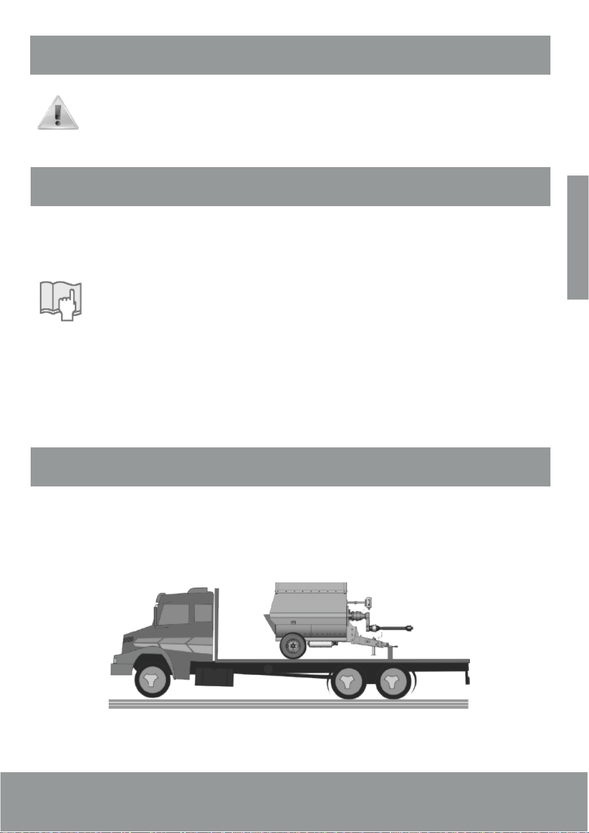
Elevation
Use only the four hooks found within the four corners of the upper
carriage compliance with the details of the scheme to the side and
performing operations with adequate equipment, depending on the
weightindicatedinthemanual.
Safety Standards
-Theinstructionsinthismanualandthoseposteddirectlyonthemixer,
inparticularthoserelatingtosecurity,shouldbereadcarefully.
- Staff who makes any kind of intervention throughout the life cycle must have rigorous technical
expertise,specific trainingand experience andrecognized byspecific sectors wherethe equipmentis
installedandknowhowtousethenecessarytoolsforworkandprotectiveequipmentequipment(PPE)
appropriate according to D. Lgs. 626/94. Failure to observe these requirements may result in risks to
safetyandhealthofpeople.
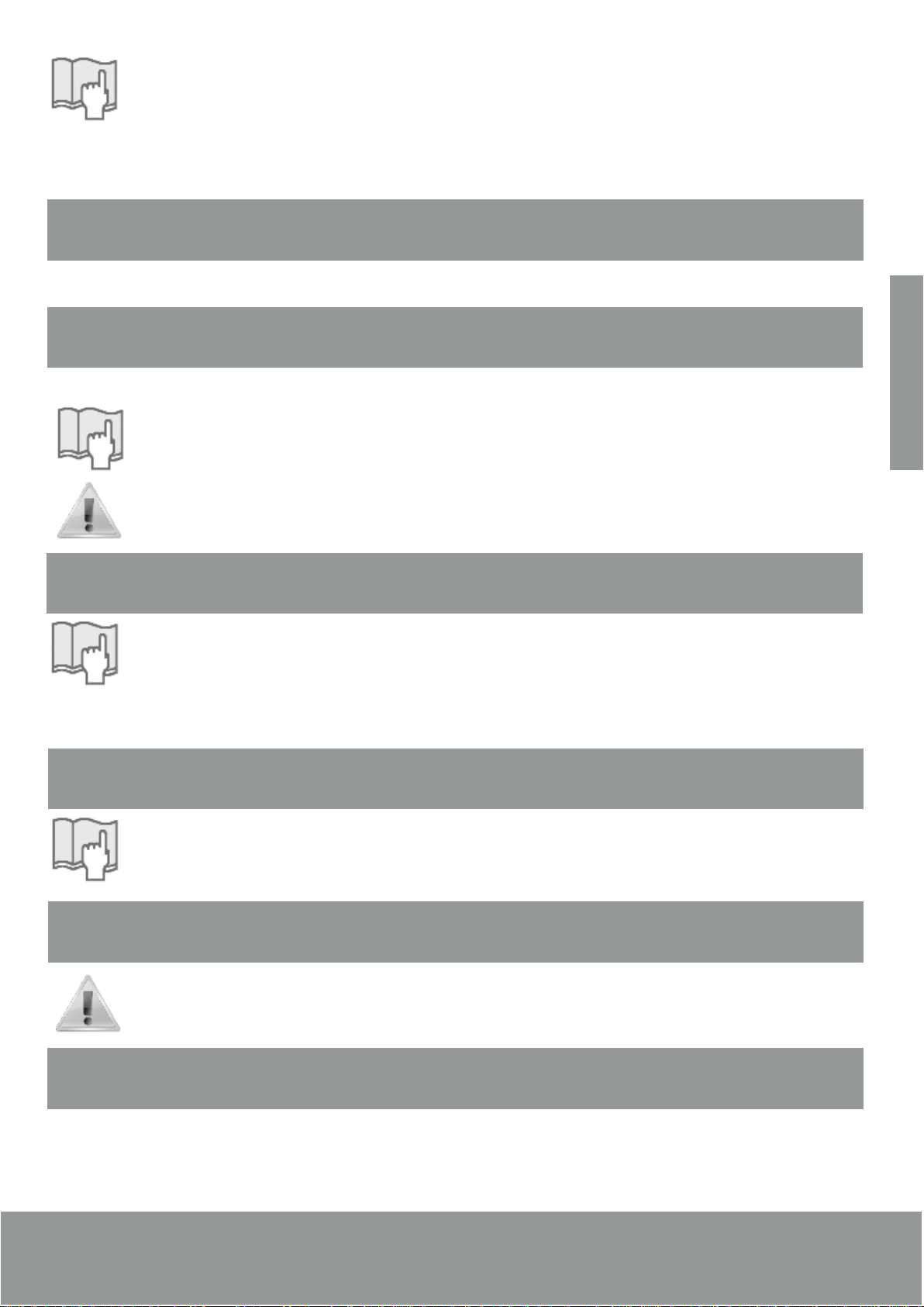
- Use the mixer for the purposes specified by the manufacturer. The use of the mixer improperly can
causerisktosafetyandhealthofpeopleandeconomiclosses.
-Keepthemixerunitatitsmaximumefficiencybyfollowingthemaintenancescheduleprovided.Good
maintenance will get better performance, a work activity over a long and constant maintenance of
safetyitems.
- To perform maintenance work in areas difficult to access or dangerous, the technical precautions
havebeentakentosafetyforhimselfandforothersinaccordancewiththelawsofsafety.
- All maintenance, inspection and repairs must only be done by a technician, aware of the risks
involved. It is therefore necessary to predict the operating procedures for the entire machine, suitable
foradministrationofthehazardsthatcanbepresentedandmethodstopreventthem.Thecoachmust
alwaysworkwithgreatcare,payingcloseattentioninobservanceofsafetystandards.
- At work, use only clothing and / or appropriate personal protective devices listed in the instructions
providedbythemanufacturerandthoseprovidedforinlawsrelatingtosafety.
-Replacewornbyoriginalspareparts.Useoilsandgreasesrecommendedbythemanufacturer.
-Donotdumppollutingmaterialsintotheenvironment.Disposeofthelawsonthematter.
-Having madethe replacement ofthe lubricant, youshould proceedto clean thesurfaces ofthe mixer
unitandthefloorneartheareaof intervention.

9
VMN 4.0
Adhesives Security
Indicationofthecorrecttirepressure. Donotgonearthecardanonmotion.
Maximumweightonthehitch1.500kg Do not clean the balance's monitor at
highpressure.
Indicates where lubrication must do and
next, attention, one should not put your
handonthematmoving.
Warning! Do not put
your hand on the door
matwhenitismoving.
English

10 Operation Technical Manual
Adhesives Security
Indicates the mounting position of the
loadcell.
Attentiontothehighpressurehose.
Range Zebra: corner or part in lifting the
machine,runintothedangerofinjury.
NEVER put hands or try to climb on the
mixer,especiallywiththesamemotion.
Attention! Part of the machine can cause
seriousdamageorinjury. Attention! Do not put your hand on the
coverofrearfeed.

Presentation of Mixer VMN 4.0
11
VMN 4.0
3.1 - Components Identification
1
10
6
14
5
4
11 16
17
329
01-Terminalcoupling
02-Header
03-SupportFoot(HydraulicJack)
04-Planetarygear
05-Wheel
06-BalanceAutoMix
07-RotorBeater
08-BreakingHay
09-HydraulicMotor
10-ConveyorBelt
11-TransmissionBox
12-Paddlemixer
13-RearLoadCell
14-FrontLoadCell
15-SupplyGrid
16-PortodDischarge
17-HydraulicCylinder
13
12
8
15
Note:
The grid supply should remain closed during operation of the mixer. Open it only when
performingvisualinspection,makingsurethatthemixeristurnedoff.
7
English

Coupling the Driveshaft
Principle of Operation
12 Operation Technical Manual
1-Makesurethatthedriveshafthastheclearancetomaneuver.
2- Couple the side of the safety screw in the gearbox of the
machine.
3-Assembletheotherpointonthetractor.
4- Secure the currents of protective cover of the driveshaft for will
not becomelooseandavoidaccidents.
5- In the end of the operation, turn the tractor at the maximum
angletomakesurethedriveshaftistotheleftlimit.
Warning:
Whenever you replace the driveshaft, replace it
withasecurityscrew.
Note:
Whenthe“left”or“right”termsareused,itisconsidered as a reference point the position of
theoperatorofthetractor.
The mixer VMN 4.0 is a device designed to perform mixing and discharge in different situations in
height.Hisprojecthasbeendesignedwithflexibilityandefficiencyinthisapplication.
Themixer performs abalanced mixture ofingredients maybe they (sorghum,grass, corn silage,bran
concentratedsaltsandotherorganicmatteretc.).
Attention:
Alwaysuntiethehayandputitseparateanduniformwayinsidethemixer.
Never leave ropes, bags, wire or any other material that is not only necessary for
animalfeedingredientsinsidethemixer.
Thebeltspeeddependsontheproductbeingdownloadedandcanberegulatedbyavalveattachedat
thebeginningofthehoseofthehydraulicmotor.
The rotor consists of mixer blades and knives to mix well, place slices of longer fibers by contact
betweenthekniveswiththecrackerofhay,makingahomogeneousmixtureofingredients.

Technical Specifications
13
VMN 4.0
Themixerrotorspeedisconstant,dependingonlyontherotationofthePTOofthetractor.
ThedischargeconveyorwithPVCsliversisdrivenbyhydraulicmotor.
Themixerhastwoloadcellsinthechassisandaloadcellonthestructureonthefront,directlylinkedto
thebalance.
2154 mm
2344 mm*
* Measured with belt open.
2184 mm
2154 mm
2184 mm
OverallHeight(A) 2.184mm
OverallWidth(L1) 2.344mm
TotalLength(C) 3.880mm
WorkingVolume 4.0m3
NominalVolume 4.0m3
MixingTime 2a4min
ApproximateWeight(Empty) 1.700kg
DownloadTime 2.0m3/minute
RequiredPower 50cv
Tire 265/70R168ply
Rim 16W8
AirChamber 16L540
Pressure 44PSI(3bar)
RotationPTO 540RPM
English

Preparation and Coupling of the Mixer VMN 4.0
14 Operation Technical Manual
2606 mm
3880 mm
Header to the tractor hitch
Note:
Thecouplingmustbeperformedinaplan.
PS. The drawbar of the tractor must have head
(asshown),preventingthetiltingofthemixer.
12
3
5
4
4
To engage the header to the tractor, follow the instructions
below:
a) Bring the tractor, aligning the drawbar (1) coupling with the
terminal(2)ofthemixer.
b) If necessary, raise or lower the header through the support
foot(Hydraulicjack)(3).
c) Install the hitch pin (4) and lock it with a cotter pin, preventing
accidentalrelease.
d) Pull the lock pin (5) and place the foot support (3) horizontal.
Then,installthelockingpinagain.
PS.DuringoperationoftheVMN4.0,thesupportinglegmustbe
inworkingposition(horizontal).
e) To have an accurate weighing, the mixer needs to be leveled.
Check the levelling of the mixer and adjust it if necessary using
theadjustmentfeatureintheheadasinstructedbelow:

15
VMN 4.0
Procedureforsettingtheheadertoleveling:
1-Chockthewheels.
2- Use the hydraulic jack and a wooden wedge to hold the VMN
4.0.
3-Loosennuts(3)andremovethescrews(4).
4- Position the header combining drilling up or down as needed,
accordingtheheightofthetractor.
5- Place the screws (4) and nuts (3) and torque (see table
torques)fromtheendofthemanual.
12
2
4
3
5
Attention:
The header weighs 120 Kg, so it will be necessary
tousea winchormore personsto holdtheheader
andavoidaccidents.
Adjust the Length of the Driveshaft
RemovingthefairingprotectingthePTO:
A)DisengagePTOmixer.
B) Follow the instructions in item Maintenance of the driveshaft,
toremovetheprotectivefairing.
For the following, the tractor should be turned
offandthekeyoutofignition.
Tractor 3 cm
3 cm
Mixer
1
2
CheckingandadjustingthelengthofthePTO:
A)Engagethetractormixer.
B) Always operate the tractor so that the rear tires to a close as
possibletotheheader.
English

Checking the Work Angle
16 Operation Technical Manual
C)Removethedriveshaft.Engagethetube(1)thetractorpower
take-offandthebar(2)inthemixer.
D)Getthepartsofthedriveshaftsidebysideandseeifthereisa
minimumclearanceof3cmateachend.
If clearance is less than the quoted or does not exist, mark and
cut the tube (1) and bar (2), and the protective tube (3), all at the
samerate(measured).
E)Withafile,removeanyburrsresultingfromthecuts.
F) Apply grease to the inner end of the tube and bar on the
cardan.
G)Reassembleallcomponentsofthecardan.
15º
The angle of 0º is the centerline of the tractor. The maximum angle allowed for PTO when it is being
drivenbytheTDP,is15º.Ifyouexceedthisvalue(example:maneuvers),unplugthepower.
Note:
With the TDP “off”, the maximum angle of the cardan maneuvers can reach a
maximumof30º.
The figure illustrates the maximum allowable tilt angle of the driveshaft with the car in motion and
drivenwithTDP:15º.IftheTDPisnotworking,themaximumangleis 30º.
Attention:
Maneuvers with TDP connected in a greather than 15º angle can cause serious
accidents.

Operating Adjustments
17
Connecting the hydraulic hoses
a) On the remote control tractor, use two outputs hydraulic: one
for opening and closing the discharge port and the other for
activatingtheunloadingbelt.
The photo with the levers (2) may vary according to
the mark and tractor size, and thus follow the
operatinginstructions.
b)Removetheprotectivecaps(1)remotecontrolandhoses.
c) Connect the terminals of these hoses pushing firmly against
theremoteterminals.
d) Bleed the circuit: to remove the air from the hoses and
cylinders, turn the levers of the remote control several times in
bothdirectionsuntiltheendofthecourse.
Themachineshouldbecoupledtothetractor.
1
2
VMN 4.0
Removing the hydraulic hoses.
a)To disconnect thehydraulic hosesis necessary torelieve the
system pressure. For this, turn off the tractor and after,
sometimescranklevers(2)relievingthesystem.
b)With thelevers (2) controlin neutral, pull the hosesquickly: a
disconnectionoccurwithminimallossofoil.
c)Next,replaceallprotectivecaps(1).
English

PTO Speed
Guidance on the Discharge Flow
18 Operation Technical Manual
During operation, rotation of power should never exceed 540 RPM in
ordertopreventthespillageofthemixture.
So you have to figure out which engine speed in decision 540 RPM that
providespower.
Forthisthesearefourpossibilities:
-Checkforapossibleindicationthetachometer(revcounter)ofthetractor.
-Checkthatthetractorhasadecalthatinformation.
-Consultthemanualofthetractor.
-Ofdoubtpersists,useatachometerdirectlyontheshaftpowertake-off.
Therearebasicallytwowaystocontroltheflowofthedischargeofthemixer:
1- Varying the rotation of the TDP(not more than 540 rpm), which controls the rotor speed mixer VMN
4.0.
2-Varyingthetravelspeedofthetractor.
3-Regulatingvalveinstalledatthebeginningofthehose.
If for example, the rotor speed of the mixer VMN 4.0 is too high relative to the mat, there could be
accumulation of material at the exit door, as well as non-uniform distribution. In the case, you should
slowthetreadmill,followingtheinstructionsoftheabove.
Ifthe beltspeed is too low comparedto therotor mixer VMN 4.0, lackingin materialoutput port. In this
case,increasetherotationoftheTDP(notmorethan540rpm).
Thetractorspeedshouldbecompatiblewiththedischargeflow.Todepositmoremixinginthetroughs,
slowdownthetractorandviceversa,butalwaysmaintainaproperrotationoftheTDP.
Make sure your tractor has a table
and/or graphic scale, informing the
travelspeed fordifferentspeedineach
gear, as illustrated below. It will help in
theworkofunloadingfront.
Never work with the PTO
rotationabove540rpm.

Operation
19
VMN 4.0
Discharge through the Conveyor Belt
a)Placethemixeratthesiteofdischarge.
b) Operate the levers of control to the hydraulic cylinder (1) lift
the discharge port (2), and the hydraulic motor (3) rotate in the
directionofthedischarge.
c) Triggering the movement of the belt in order to discharge,
where the mixture will be conducted to the discharge location
definedbytheoperator(troughs).
d) Move the tractor at a speed compatible with the discharge
flow,inordertoobtainauniformdistribution.
e) Note the behavior of the belt and adjust its speed by varying
therotationofpowertake-off.
f) After unloading, close the discharge port (2) and make sure
thattheconveyoriscompletelystopped.
1
3
2
Attention:
NEVER operate the turning of the belt with the
doorclosedorthebeltinposition1oftransport.
a) Use this feature to discharge troughs and whenever
necessary.
b) The discharge conveyor has five different levels of height can
beadjustedquickly.
c)Liftthefrontofthetreadmill (3) slightly until thehinge pinto be
suspended.
d) Lift the front of the belt (5) slightly until the hinge pin to be
suspended.
e)Pullthesupportbelt(4)tounlockthepin.
f)Movethebelt(4)upordowntothedesiredposition.
g)Pushthelatchsupportbelt(4)tofitthepin.
4
5
Adjusting the Conveyor Belt
English

20 Operation Technical Manual
Note:
1-Askforhelpofanotherpersontofacilitatetheoperation.
2-Onlyperformthisprocedurewithconveyorandmixerinactive.
3-Ensurethatthebelt(4)isactuallylocked.
4- To carry out this operation, the tractor must be off and the PTO disconnected from the
outletofthemixerVMN4.0.
Balance Automix
Seemanualofthescale
Grease Lubrication Points
1
2
Maintenance Instructions
POINTS PERIOD GREASE RECOMMENDED
Foot support (1) Every 50 hours or weekly
work
Grease the base of Lithium (Li)
Class 2
Shaft Belt (2)
Every 10 hours
Discharge conveyor
bearings (3)
PTO spreaders (4)
Other manuals for VMN 4.0
1
Table of contents
Languages: