Nokia 447PRO User manual

ZB1660A
02.00
SMH164C
When re---ordering manuals, please quote the model name and part number.
Level
SMA249C
xx
Contents
Service
Chassis 447R
Part List
PCB Part List
PCB Layout pictures
Monitor Dismantling
CRTmodule .............
MainBoardmodule ......
1
Nokia Display Products Oy
P. O . B o x 1 4
FIN---24101 Salo, Finland
17” High Resolution Colour Monitor
447PRO
2
SMH164C
SMA249E

447R

447R 1
Service
Contents
1. Product Overview
1.1. Technical Specifications
1.2. Preset Display Modes
1.3. S---Capacitor and Linearity Control Table
1.4. Audio (Optional)
1.5. USB subsystem (Optional)
1.6. Monitor Connection
1.6.1. If your monitor is DDC compatible (PC)
1.6.2. If there is no DDC in your computer (PC)
1.7. User controls
1.8. Menu
1.8.1. Moving in the Menu
1.8.2. Exit Menu
1.8.3. Default Adjustment
1.8.4. Brightness and Contrast
2. Site Preparation
2.1. Location
2.2. Troubleshooting
2.3. Checking the Operation of PowerSaver
3. Controlling the Memory for Picture Adjustments
3.1. Memory for User Adjustments
3.1.1. Adjustment
3.1.2. Resetting the User Memory
3.2. Memory for Factory Adjustments
3.2.1. Adjustment
4. Service Mode
4.1. Grouping of the adjustments
4.2. Service Menu
4.2.1. Access to the Service Mode
4.2.2. Geometry
4.2.3. Grey Scale
4.2.4. Initializing the Replacement IC (IC203 on SMA)
4.2.5. Storing Adjustments
4.2.6. Exit from Service Mode
5. Workshop Maintenance
5.1. Important Safety Notice
5.1.1. Discharging the CRT
5.2. ESD---Sensitive Parts
5.3. Test Equipment
5.4. Test Patterns
5.5. Disassembly
6. Image Performance
6.1. Active Picture Size and Location
6.2. Geometrical Distortion
6.3. Straightness of Line Segment
6.4. Linearity
6.5. Phosphor Color Coordinates
6.6. Color Temperature and Tracking
6.7. White Uniformity
6.8. Luminance
6.9. Convergence
7. Adjustment Procedure
7.1. Adjustment Flow Diagram
7.2. Preliminary Preparations
7.2.1. High Voltage
7.3. Geometry
7.4. Grey Scale

447R
2
7.4.1. The Most Sensitive Colour
7.4.2. Low Light
7.4.3. High Light
7.5. Maximum/Minimum Contrast
7.6. Focus
7.7. Convergence
7.7.1. Measuring Conditions
7.7.2. Convergence Measuring Gauge
7.7.3. Static Convergence
7.7.4. Dynamic Convergence
7.7.5. Allowed Error Levels for Convergence
7.8. Colour Purity
8. Screen and Faceplate Blemishes
8.1. Quality Area
8.1.1. Definitions of inspection quality
8.2. Face Defects Limits
8.3. Glass Blemishes
8.3.1. Scratches
8.3.2. Bubbles
8.3.3. Foreign Materials
Revision History
Rev Date Prepared by Comments
08.99 30.08.1999 J.Paukku
02.00 09.02.2000 J.Paukku SMA249E added

447R 3
1. Product Overview
447R is a 17 inch monitor. The maximum resolution of 1600 x 1200 makes the monitor suitable for
PC, Macintosh and workstation applications in normally heated, ventialed and controlled office/home
environment. The monitor has an own power supply with input voltage requirements from 90V to
264V.
1.1. Technical Specifications
Cathode Ray Tube 17” in diagonal, 90˚deflection angle..........
non---glare, antistatic coating
Short persistence (P22)
Dot pitch 0.25 mm
Picture Size 312 mm x 234 mm with specified geometric distortion................
Maximum Picture Size 325.5 mm x 241.5 mm, diagonally 404.9 mm (16.0”).......
Power Input Requirements Voltage 90---264 V, 50/60 Hz Autosense...
Current 1.8 A/100 V, 0.7 A/240 V
Power Dissipation < 120 W (maximum 130W) Normal Operation...........
<10WSuspend
< 5 W Auto power off (3 W typically)
<1WActiveoff
Memory Locations 19 for factory preset timings...........
3 for user adjusted timings
Geometric Distortion The distance between bezel and active screen edge shall not vary.........
more than 2 mm in both vertical and horizontal dimensions
Luminance Min. 90 cdm---2 (nits) at center, with full white field.................
Video Input Input Signal: RGB, analog, positive, max 0.7 V/75 τ.................
Horizontal addressability: 1600 dots maximum
Vertical addressability: 1200 dots maximum
Synchronization Range Horizontal: 30 kHz to 96 kHz automatic......
Vertical: 50 Hz to 150 Hz automatic
Synchronization Signal Separate TTL, positive/negative.......
Composite TTL, positive/negative
Max. Dot Frequency Capability 160 MHz
DDC 1/2AB.......................
Temperature Operating: +10˚Cto+40˚C................
Pa c k e d : --- 2 0 ˚Cto+60˚C
Humidity Operating: 15% to 85 %...................
Packed: 5% to 95 %
Weight 19 kg net.....................
22 kg gross
Size, Tilt and Swivel
90
20
90
5
h
dw
Dimensions
Monitor h 432 mm.................... .........
w 433 mm........
d 441 mm.........
Package H 567 mm................... ........
W 562 mm........
D 582 mm........

447R
4
1.2. Preset Display Modes
H Front Porch
Video
Full
intensity 0.7 V
Blanking 0 V
H Active Video
HSync
HBlanking
Left BorderRight Border
HBackporch
HSync.
Signal
V Front Porch VBackPorch
Video
Full
intensity 0.7 V
Blanking 0 V
V Active Video
VSync
VBlanking
Bottom Border Upper Border
VSync.
Signal
M o d e s 0 0 --- 0 2 a r e a d j u s t e d t i m i n g s . M o d e s 0 3 --- 1 4 a r e p r e a d j u s t e d t i m i n g s .
Memory location--> 0123456789
Display Mode
Name
NCE642 NCE513 NCE70X NCE700 NCE605 NCE603 NCE506 NCE501 NCE40A NCE406
H Frequency/kHz 91.146 68.68 93.755 74.995 79.976 63.981 60.023 48.363 53.674 46.875
H Period/μs10.971 14.561 10.666 13.334 12.504 15.630 16.660 20.677 18.631 21.333
H Active Video/μs8.127 10.836 7.901 9.877 9.481 11.852 13.003 15.754 14.222 16.162
H Resolution 1280 1024 1600 1600 1286 1280 1024 1024 800 800
H Sync/μs1.016 1.016 0.948 1.185 1.062 1.037 1.219 2.092 1.138 1.616
H Back Porch/μs1.42 2.201 1.501 1.883 1.843 2.296 2.235 2.462 2.702 3.232
V Frequency/Hz 85.0 85.0 75.0 60.0 75.0 60.0 75.0 60.0 85.1 75.0
V Period/Lines 1072 808 1250 1250 1066 1066 800 806 631 625
V Resolution 1024 768 1200 1200 1024 1024 768 768 600 600
V Sync/Lines 3333333633
V Back Porch/
Lines
44 36 46 46 38 38 28 29 27 21
H sync Polarity +++++++-- + +
V sync Polarity +++++++-- + +
H Front Porch/μs0.41 0.51 0.32 0.39 0.12 0.44 0.20 0.37 0.57 0.32
V Front Porch/
Lines
1111111311
Dot Frequency/
MHz
157.500 94.500 202.510 161.990 135.640 108.000 78.750 65.000 56.250 49.500
Interlacing no no no no no no no no no no

447R 5
H Front Porch
Video
Full
intensity 0.7 V
Blanking 0 V
H Active Video
HSync
HBlanking
Left BorderRight Border
HBackporch
HSync.
Signal
V Front Porch VBackPorch
Video
Full
intensity 0.7 V
Blanking 0 V
V Active Video
VSync
VBlanking
Bottom Border Upper Border
VSync.
Signal
Memory location--> 10 11 12 13 14 15 16 17 18
Display Mode
Name
NCE401 NCE30A NCE306 NCE300 NCE200D NCE013 NCE012 NCE014 NCE011
H Frequency/kHz 37.879 43.2690 37.500 31.472 31.467 77.494 67.500 54.348 68.681
H Period/μs26.400 23.111 26.667 31.774 31.780 12.904 14.815 18.400 14.560
H Active Video/μs20.000 17.778 20.317 25.420 25.423 9.481 10.667 14.400 11.520
H Resolution 800 640 640 640 720 1152 1152 1152 1152
H Sync/μs3.200 1.556 2.032 3.813 3.814 1.053 1.185 1.200 1.280
H Back Porch/μs1.00 2.222 3.810 1.906 1.907 1.843 2.370 2.400 1.440
V Frequency/Hz 60.3 85.0 75.0 59.9 70.1 85.1 75.0 60.1 75.1
V Period/Lines 628 509 500 525 449 911 900 905 915
V Resolution 600 480 480 480 400 864 864 864 870
V Sync/Lines 4 3 3 2 2 3 3 3 3
V Back Porch/
Lines
23 25 16 33 34 43 32 37 39
H sync Polarity +-- -- -- -- +++--
V sync Polarity +-- -- -- + +++--
H Front Porch/μs1.00 1.56 0.51 0.64 0.64 0.53 0.59 0.40 0.32
V Front Porch/
Lines
11110 13 1 1 1 3
Dot Frequency/
MHz
40.000 36.000 31.500 25.177 56.640 121.510 108.000 80.000 100.000
Interlacing no no no no no no no no no

447R
6
1.3. S---Capacitor and Linearity Control Table
Timings S5 S4 S3 S2 S1 S0 LIN1 LIN2
NCE642 0 0 0 0 0 1 0 0
NCE605 0 0 0 0 1 1 0 0
NCE700 0 0 0 1 0 0 0 0
NCE513 0 0 0 1 0 0 0 0
NCE603 0 0 1 0 0 1 0 0
NCE506 0 0 1 1 0 1 1 0
NCE40A 0 1 0 0 1 0 1 0
NCE501 0 1 0 1 1 1 1 0
NCE406 0 1 1 0 0 0 1 0
NCE30A 0 1 1 1 1 0 1 0
NCE401 1 0 0 1 1 0 1 1
NCE306 1 0 0 1 1 1 1 1
NCE200D 1 1 1 1 1 1 1 1
NCE300 1 1 1 1 1 1 1 1

447R 7
1.4. Audio
1.4.1. Connectors
Audio in L & R RCA
Input level at clipping 3.0 Vpp
Mic line out
Head phone 3.5 mm
External mic 3.5 mm for electre condenser microphone
1.4.2. Amplifier
Output power 2 * 3.0 W (RMS) to 16 τload
1.4.3. Loudspeakers
Nominal power 5W
Nominal inpedance 16 τ
Frequency range 200 Hz --- 18 KHz
1.4.4. Special Features
Volume---control Adjusted via OSM or Menu knob
Balance---control
B a s s --- c o n t r o l ±12 dB
Tr e b l e --- c o n t r o l ±12 dB
National 3D sound Enhanced stereo sound
Line out Line in
R L MIC

447R
8
1.5. USB Subsystem
1.5.1. General
USB is standard serial bus for connecting peripherals to your PC. USB is the key to true Plug and
Play capabilities of your PC.
- USB enables you to attach and detach new peripherals while your PC is running.
- You don’t have to wonder about which port of the PC you should use when plugging in a
peripheral. since all four---pin USB connectors accept any USB peripheral to be connected, there
isnowaytodoitwrong.
- Also the need for configuring and booting in adding or removing new peripherals disappears.
USB itself detects and configures peripherals as soon as they are attached or deattached.
- It allows your system to grow in response to your needs without extra costs. In theory USB
supports up to 127 devices.
- USB has a wide industry support among leading computer, telecommunications, electronics and
software companies.
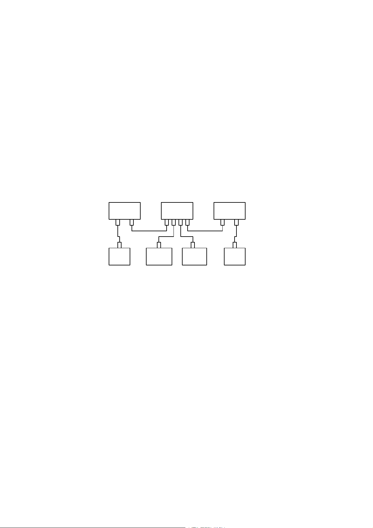
USB requires one host in any USB system: it is normally the PC. Only one USB device has to be in
direct connection to the PC and the others can be connected through USB hubs. Each hub has
downstream ports for attaching peripherals and one upstream port for connection towards the host.
The picture below illustrates the USB system.
HUB HUB HOST
Keyboard Monitor PC
Mouse Speaker Micro--
phone Phone
11
1 Upstream port
USB has two data bandwidths, which can be in use simultaneously:
- The high-speed bandwidth (12Mbps) supports multimedia and telephony devices
- The low-speed bandwidth (1.5Mbps) is dedicated for low-end devices like keyboards and mice
USB enables transferring compressed video for teleconferences, but it cannot handle moving video
with high resolution.
USB devices can be divided into two categories, namely bus-powered and self-powered devices:
- Self-powered devices take their power from the mains supply
- Bus-powered devices rely on the power supplied by the USB cable. In the picture before low-
power devices like keyboard and mouse can be called as, low power, bus-powered devices (3
100 mA)
Each USB cable segment provides +5 volts of power. The maximum length of USB cable segment
is 5 meters.
The host in the system is responsible for allocating USB bandwidth for transferring information. Data
transfer over the USB cable starts with synchronization information. This information is called the
Token Packet. It includes information about the type and the direction of the transfer, USB device
address and an endpoint number. After that follows the actual Data Packet or control information.
The destination of the transfer answers with a Handshake Packet as a mark of a successful transfer.
USB error rate is very low, but in case of an error USB hardware will retry sending three times before
informing the software about the error
In addition the host (or the PC) detects the attachment or removal of any USB device. All USB de-
vices are attached to the USB through hubs. They indicate the removal or attachment of a USB de-
vice in their port status.
After that the host of the system enables the port and defines a unique USB address for the device.
In case of a device removal the hub disables the port and gives an indication of device detachment
tothehost.Iftheaddedorremoveddeviceisahubtheaboveproceduremustbeperformedforall
the attached peripherals.

447R 9
1.5.2. Bus powered connections
Low power: All power to these devices comes from USB connector. They may draw no more than
one unit load (100 mA)at any time.
High power: All power to these devices comes from USB connector. They must draw no more than
one unit load upon power up and may draw up to five unit loads after being configured.
1.5.3. Universal Serial Bus Hub
The USB provides Plug and Play capabilities for peripherals. The bus physical interconnection is a
tiered star topology. USB system provides hub for four downstream devides.
1.5.4. USB ports
Unit is capable to handle 4 connected downstream USB devides from the HUB. There are so 4 pcs
serie A and one piece serie B for upstream (root) connectors in the rear of the monitor. These can
be used for any PC based application as keyboard, mouse, printer, scanner, modem, etc.
Display controls and alignments via PC:
- Power mode: ON, Stand---by, Suspend, OFF
- Controlcodes: Brightness,Contrast,RGain,GGain,B,Gain,RBlackLevel,GBlackLevel
B Black Level, H Position, H Size, H Pin Balance, V Position, V Size,
H Moire, V Moire, Parallelogram Distortion, Trapezoidal Distortion, Tilt
1.5.5. USB connectors
The data is transferred differentially meaning low radiation. The driver delivers initially ≥2V swing to
the cable of Z0=90τ±15%. Data signal rise time is 4 nsmin and 20 nsmax. A d d --- o n j i t t e r f r o m
driver is < 3 ns. Maximum cable length is 5 m.
The differential receiver sensitivity is at least 200 mv. Maximum allowed jitter is 25 ns.
The port supplies 4,75V --- 5,25V having current up to 0.5 A to the peripherals. Combined 3 port cur-
rent limitation is provided for safety reasons. Current of the 0.5 mA is taken in suspend mode and
starting current of 0.1 A is quaranteed.
Type A (downstream) Type B (upstream)
1. Vcc
2. Data --
3. Data +
4. GND

447R
10
1.6. Monitor Connection
Make sure that the monitor is disconnected from mains and the power switches of
the computer and all attached devices are turned off before connecting the monitor.
- Connect the signal cable plug to the videocontroller connector at the back of the computer.
- Tighten the screws on the plug by hand.
- Connect the power cord first to the monitor and then to a grounded power outlet.
1.4.1. If your monitor is DDC compatible (PC)
- Do not use any adapter when connecting signal cable to your computer.
- Do not extend the signal cable with extension lead. The DDC signals will not accept extended
cable.
1.4.2. If there is no DDC in your computer (PC)
- Normally there is no need for adaptor when connecting signal cable to your computer.
- Use MAC adaptor in signal cable when connecting the monitor to an Apple
Macintosh computer.
- If the computer is equipped with separate display adapter card. It may have a standard
D---SUB connector. In that case MAC adaptor is not needed.
Signal connector
Pin Signal
1--->RVRedvideo
2 ---> GV Green video
3 ---> BV Blue video
4 < --- ID2 (grounded)
5 Signal cable plugged/unplugged
6 RG Red ground
7 GG Green ground
8 BG Blue ground
9 ---> DDC +5V
10 LG Logic ground
11 < --- ID0 (Grounded)
12 < --- SDA DDC SDA
13 ---> Hs Horizontal sync., Composite sync.
14 ---> Vs Vertical sync.
15 < --- SCL DDC SCL
15
610
11 15

447R 11
1.7. User Controls
Turning the Monitor ON and OFF
Push the power switch to turn the monitor on or off.
Power indicator
Power switch
Brightness
Navi (menu) & button
Contrast
When the power is turned on, the power-- on indicator will light.
The colour of the the power---on light indicates the operating state of the monitor.
- Green: The monitor is in normal operation or stand ---by state.
- Blinking Green: The monitor is in automatic suspend or power off state.
- Not illuminated: The monitor is turned off with power switch or disconnected from mains outlet.
If the power management function working properly in your computer, you do not need to switch the
monitor on or off. It happens automatically.
The power switch does not disconnect the
monitor from mains. In oder to make the monitor
completely powerless, unplug the power cord
from power outlet.

447R
12
1.8. Menu
All adjustments and settings are covered with following main menu displays:
SIZE & POSITION . . .
SHAPE...
COLOR...
AUDIO
MISCELLANEOUS ...
Menu line written in upper section of the menu display is a headline of another menu display.
Menulineswritteninlowersectioncontainapropertywhichyoumayadjustorperformsettings.
1.8.1. Moving in the Menu
Menu operations are controlled with button and Navi button.
aCall the menu to the screen by pushing button.
bSelect the header with navi button.
cPush to confirm the selection.
Adjustment and settings corresponding the header appear below the header field.
dSelect the adjustment with navi buttons.
ePush to confirm the selection.
Menu disappears and a scale shows the position of the adjustment. In addition to the bar, position
of the adjustment is shown as a percentage of the maximum value. The upper number shows the
current value and the lower one shows the value where the adjustment started.
fAdjust with navi buttons.
gWhen ready, push button.
1.8.2. Exit Menu
All displays disappear automatically in 20 seconds or at once by selecting EXIT MENU and pushing
button.
1.8.3. Default Adjustment
After the menu display has disappeared, the latest adjustment can be called to the screen simply by
pushing navi button.
1.8.4. Brightness and Contrast
With brightness adjustment you may control the brightness of the whole picture. Contrast increases
or decreases the brightness difference between light and dark colors. Adjust brightness and con-
trast adequately according to ambient light conditions to obtain the best picture quality.

447R 13
TILT
30%
PREVIOUS VALUE: 40%
ADJUST: --/+ OK:
SIZE & POSITION
SHAPE...
COLOR...
AUDIO
MISCELLANEOUS
EXIT MENU
AUTO SHAPE
HORIZONTAL CENTERING
WIDTH
VERTICAL CENTERING
HEIGHT
HORIZONTAL CENTERING
53%
PREVIOUS VALUE: 50%
HEIGHT
30%
PREVIOUS VALUE: 40%
a
b
e
f
g
c
d
SIZE & POSITION
SHAPE
COLOR...
AUDIO
MISCELLANEOUS
EXIT MENU
DEFAULT SHAPE
TILT
ORTHOGONALITY
TRAPEZOID
PINCUSHION
PINCUSHION BALANCE
WIDTH
44%
PREVIOUS VALUE: 50%
VERTICAL CENTERING
45%
PREVIOUS VALUE: 50%
6500K, 7000K, 8000K, 9300K, 10000K,
Custom1, Custom2
MOVE -- / + SELECT:
NOKIA 447PRO 75Hz
ADJUST: --/+ OK:
ADJUST: --/+ OK:
ADJUST: --/+ OK:
ADJUST: --/+ OK:
MOVE -- / + SELECT:
NOKIA 447PRO 75Hz
ORTHOGONALITY
30%
PREVIOUS VALUE: 40%
ADJUST: --/+ OK:
TRAPEDOIZ
30%
PREVIOUS VALUE: 40%
ADJUST: --/+ OK:
PINCUSHION
30%
PREVIOUS VALUE: 40%
ADJUST: --/+ OK:
PINCUSHION BALANCE
30%
PREVIOUS VALUE: 40%
ADJUST: --/+ OK:
SIZE & POSITION
SHAPE
COLOR...
AUDIO
MISCELLANEOUS
EXIT MENU
DEFAULT COLOR
COLOR PRESETS 9300 K
RED
GREEN
BLUE
SAVE CURRENT COLOR
MOVE -- / + SELECT:
NOKIA 447PRO 75Hz
SIZE & POSITION
SHAPE
COLOR...
AUDIO
MISCELLANEOUS
EXIT MENU
BALANCE
VOLUME
BASS
TREBLE
MIC. LEVEL
STEREO MODE: STEREO
MIC. SELECT: INTERNAL
SPEAKER: ON
MICROPHONE: ON
MOVE -- / + SELECT:
NOKIA 447PRO 75Hz
SIZE & POSITION
SHAPE...
COLOR...
AUDIO
MISCELLANEOUS
EXIT MENU
MONITOR DEFAULTS
MOIRE
DEMAGNETIZE
ABOUT MONITOR
MENU OPTIONS
MOVE -- / + SELECT:
NOKIA 447PRO 75Hz
MENU OPTIONS
LANGUAGE/SPRACHE/LANGUE
HORIZONTAL POSITION
VERTICAL POSITION
DISAPPEARANCE TIME 1:00
BACK
ADJUST: --/+ OK:
LANGUAGE/SPRACHE/LANGUE
ENGLISH
DEUTSCH
SVENSKA
SUOMI
ITALIANO
FRANCAIS
ESPANOL
CANCEL
ADJUST: --/+ OK:
MOIRE
30%
PREVIOUS VALUE: 40%
ADJUST: --/+ OK:
LR
NAVI
NAVI

447R
14
2. Site Preparation
2.1. Location
This Monitor is designed for normal office conditions. It is equipped with own power supply. It is not
to be serviced or repaired on site
2.2. Troubleshooting
Local service facilities should perform simple maintenance such as trimming. More advanced main-
tenance and repair that requires replacement of components which in turn requires testing and re-
trimming should be carried out in a central workshop.
Symptom Measures
Picture
screen is
blank
The indi-
cator on
the front
panel is
not illumi-
n
a
t
e
d
Check that the power cord is correctly connected to the monitor and to the power
outlet. If the monitor is powered through the computer, check that the computer is
switched on with the mains switch. Use a desk light, for example, to verify that
current is connected to a power outlet. If no electricity is connected to the outlet,
call an electrician.
nated Unplug the monitor from power outlet for about one minute.
The indi-
cator on
t
h
f
t
Check that the signal cable connector is connected. If the connector is loose
tighten the connector’s screws.
the front
panel is il-
l
u
m
i
n
a
t
e
d
The Monitor might be in stand ---by position. Push one of the buttons or move the
mouse.
l
u
m
i
n
a
t
e
d
U
n
p
l
u
g
t
h
e
m
o
n
i
t
o
r
f
r
o
m
o
u
t
l
e
t
f
o
r
a
b
o
u
t
o
n
e
m
i
n
u
t
e
U
np
l
ug
t
h
emon
i
t
or
f
rom ou
t
l
e
t
f
or a
b
ou
t
one m
i
nu
t
e.
Switch off the monitor and the computer. Remove the signal cable from the
computer. Switch on the monitor using the power switch. If the Selftest menu
appears on the screen, it is evident that the monitor functions correctly and
the problem is caused by an error in other parts of the system.
Check the signal cable’s connection pins. If the pins are slightly distorted,
usenoseplierstostraightenthem.
The Selftest menu appears. The computer may use a timing values which are
out of the monitor’s synchronization range.
Picture has colour de-
f
t
Demagnetize the monitor.
fects If colour defect is repeated without the monitor having been moved, it is possible
that the monitor is influenced by a strong magnetic interference field (near to
a high power cable, for example). Try to find a better location for the monitor or
the interference source. Note that another monitor placed too near (less than
30 cm.) may also generate interference in the picture.
Picture has strong color
defect,
Open the Miscellaneous/Selftest menu. Check the color of the Red, Green and
Blue bars. If they have pure colors, the fault is not in the monitor. Check signal
cable connectors and the computer. If the menu itself and the color bars are
discolored, the monitor is obviously damaged.
Pictureisstablebutdis-
torted
Your computer may use a timing for which the corresponding picture characteris---
tic adjustments have not been set at the factory. Adjust the picture characteristics
Picture is unstable Check the proximity of other electrical devices that generate magnetic fields,
such as speakers, other monitors, electric fans and fluorescent light fixtures.
s
u
c
a
s
s
p
e
a
e
s
,
o
t
e
o
t
o
s
,
e
e
c
t
c
a
s
a
d
u
o
e
s
c
e
t
g
t
t
u
e
s
Make sure your computer and video card are properly configured for your
monitor.
The automatical appearance of the Selftest menu on the screen means that the signal is faulty or
missing.

447R 15
2.3. Checking the Operation of PowerSaver
The proper operation of the function requires a computer with VESA DPMS power management
capabilities. Note that the power saving feature must be activated in the computer when checking
the operation.
State Colour of the power ---on indicator Monitor
Normal Operation Green Normal functions
Stand---by Green, frequency 2Hz Stand by, recovery 2s
Suspend Green, frequency 2Hz Suspend, recovery 20s
Power off Blinking green, frequency 1,5 Hz No user functions (MCU
operates on background)
Power key power off Not illuminated No functions
DPMS (Display Power Management Signaling) is a trade mark of Video Electronics Standard Association (VESA)

447R
16
3. Controlling the Memory for Picture Adjustments
Thepictureadjustmentvaluesarestoredinnon-volatilememory.Thememoryhasseparatedareas
for User Adjustments and for Factory Adjustments.
3.1. Memory for User Adjustments
3.1.1. Adjustment
1If there are values available in the memory for user adjustments, corresponding to the present
timing signals, they are always used.
2New user made adjustments are stored to the memory for user adjustments.
3.1.2. Resetting the User made settings
3User memory can be emptied from user made settings. Resetting affects only the timing
which is currently active. The reset function is inhibited if no corresponding factory preset dis-
play mode exists.
After resetting all picture properties are coming from memory for factory adjustments.
3.2. Memory for Factory Adjustments
3.2.1. Adjustment
4Factory adjustments can be updated with service menu in service mode. If there is no location in
factory adjustment memory for timings currently in use, the adjustment affects the memory for
user adjustments.
- If the memory location mentioned in case 1is empty, the picture adjustment values are read
from memory for factory adjustments. Factory adjustments, corresponding to the current tim-
ings, are transferred to user memory if any picture property is adjusted. After that the operation
is as in case 1.
Memory for Basic
Adjustments,
NCE642
1
4
3
4
The memory can be
updated with Service
menu in Service Mode
The memory can be
updated with User Menu
in User Mode
Initialization
Memory for
User
Adjustments
SMA IC203
Memory for
Factory
Adjustments
SMA IC203
Preset
Recall
Geometry
image
Storing
2
Refer to the chapter
”Service Mode”

447R 17
4. Service Mode
Service Mode is needed for updating of the factory adjustments for timings listed in the chapter Pre-
set Display Modes. If there is no location in factory adjustment memory for display mode currently in
use, the adjustment affects the memory for user adjustments.
4.1. Grouping of the Adjustments
There are two groups of software adjustments in service mode:
- Geometry set
- Grey Scale adjustment set
The following table shows how the adjustments act in relation to the display modes.
Adjustment Common for
all Display
modes
Separate for
each Display
mode
Available in
User Mode
Available in
Service Mode
Horizontal Centering XXX
Vertical centering XXX
Height XXX
Width XXX
Pincushion XXX
Trapezoid XXX
Orthogonality XXX
Tilt XXX
Moire XXX
Pincushion balance XXX
S correction X X
C correction X X
E/W corner X X
G2 X X
Min contrast X X
Max contrast X X
R Blacklevel X X
G Blacklevel X X
B Blacklevel X X
RAmp X X
GAmp X X
BAmp X X
Common adjustments need to be adjusted only once. Separate adjustment must be performed for
every display mode to be stored.

447R
18
4.2. Service Menu
4.2.1. Access to Service Mode
Active the service mode always in 91.15 kHz/85 Hz (NCE642 ).
First switch OFF the monitor with power switch.
1) Push button down.
2) While keeping button down, switch ON the monitor.
3) Release button when the power-- on indicator is illuminated.
4) Press button.
5) Give password 7711.
6) Go to OK
6) Press button
Select the items in the Menu with the --- or + buttons. Push button to open Geometry, Grey
Scale, Product Information or Memory Settings. Adjust each property with navi button.
4.2.2. Geometry
Geometry submenu contain placement, size and shape adjustments.
GEOMETRY...
GREYSCALE...
PRODUCT INFORMATION . . .
MEMORY SETTINGS . . .
WIDTH PRESET
RASTER
WIDTH
HORIZONTAL CENTERING
HEIGHT
VERTICAL CENTERING
PINCUSHION
PINCUSHION BALANCE
TRAPEZOID
ORTHOGONALITY
S CORRECTION
C CORRECTION
E/W CORNER
TILT
V. M O I R E
MOIRE
00: 1280 X 1024 85 Hz
NOKIA 447PRO 85Hz
4.2.3. Grey Scale
This monitor has sexen preset tints. With tint numbers smaller than 4 the picture becomes reddish
and with tint numbers greater than 4 the picture turns blue.
Tint no 1 2 3 4 5 6 7
Colour Temperature 5000K 6000K 6500K 7000K 8000K 9300K 10000K
The grey scale adjustment affects directly tint number 6 (9300K) only. Other tints are derived auto-
matically from 9300K colour temperature.
GEOMETRY...
GREYSCALE...
PRODUCT INFORMATION . . .
MEMORY SETTINGS . . .
EXIT MENU
CONTRAST
MIN CONTRAST
MAX CONTRAST
BRIGHTNESS
G2
RED BLACK LEVEL
GREEN BLACK LEVEL
BLUE BLACK LEVEL
RED AMP.
GREEN AMP.
BLUE AMP.
00: 1280X1024 85Hz
GEOMETRY...
GREYSCALE...
PRODUCT INFORMATION . . .
MEMORY SETTINGS . . .
EXIT MENU
MODEL: NOKIA 447PRO
SERIAL NUMBER 9919000398
POWER ON HOURS 23
S T A N D --- B Y H O U R S 0
SUSPEND HOURS 0
ACTIVE --- OFF HOURS 0
FIRMWARE 0.28
00: 1280X1024 85 Hz
GEOMETRY...
GREYSCALE...
PRODUCT INFORMATION . . .
MEMORY SETTINGS . . .
EXIT MENU
TYPE : BRAND
CRT: AG
DDC : EXT. (24LC21)
AUDIO : ON
INITIALIZE EEPROM
00: 1280X1024 85 Hz
NOKIA 447PRO 85Hz NOKIA 447PRO 85Hz NOKIA 447PRO 85Hz
Table of contents
Other Nokia Monitor manuals