Nome nmas Simple User manual

Table of contents
General...........................................................................................................................................................4
Product description........................................................................................................................................4
Safety information..........................................................................................................................................4
Intended use...................................................................................................................................................4
Support / Manufacturer..................................................................................................................................5
Terminology...................................................................................................................................................6
Measurement interface (MI)......................................................................................................................6
Signal.........................................................................................................................................................6
igure.........................................................................................................................................................6
Warning and Alarm...................................................................................................................................7
Warning and Alarm Configurations..........................................................................................................8
Nmas Hardware..............................................................................................................................................9
nmas Simple..............................................................................................................................................9
Nmas Hardware Components........................................................................................................................9
SU (Sensor Unit).......................................................................................................................................9
LD (Local Data)........................................................................................................................................9
RD (Remote Display)..............................................................................................................................10
WR (Wireless Router).............................................................................................................................10
Server......................................................................................................................................................10
Nmas Software.............................................................................................................................................10
nmas Simple software.............................................................................................................................10
nmas RD software...................................................................................................................................10
nmas Server software..............................................................................................................................10
Nmas Software Components........................................................................................................................10
LD View..................................................................................................................................................10
View........................................................................................................................................................10
Analysator...............................................................................................................................................11
Configurator............................................................................................................................................11
Signal processing.........................................................................................................................................11
Analog-to-digital converter.....................................................................................................................11
High frequency measurement AD-converter...........................................................................................11
Low frequency measurement AD-converter...........................................................................................12
nmas Data Management...............................................................................................................................12
Nmas Simple components............................................................................................................................13
Carrying case...........................................................................................................................................13
nmas Simple unit.....................................................................................................................................14
Acceleration sensors................................................................................................................................15
Acceleration sensor cables......................................................................................................................16
Magnetic base for accelerometers...........................................................................................................17
Tachometer (Speed sensor).....................................................................................................................18
Magnetic base stand for tachometer........................................................................................................19
Preparing for use nmas Simple....................................................................................................................20
Overview.................................................................................................................................................20
Local display...........................................................................................................................................20
Start / Stop..........................................................................................................................................21
Result list............................................................................................................................................23
Connection information......................................................................................................................24
Device name.......................................................................................................................................25
Trend...................................................................................................................................................25
Connection possibilities...............................................................................................................................26
Local nmas_network...............................................................................................................................26
Page 2

nmas Simple
Local network..........................................................................................................................................27
Remote connection..................................................................................................................................28
Cloud service...........................................................................................................................................29
Default configurations of nmas Simple.......................................................................................................30
Configuring nmas Simple........................................................................................................................30
Connectors...................................................................................................................................................31
Connector pin-out....................................................................................................................................32
Start measurements on nmas Simple.......................................................................................................33
Start remote connections on nmas WR (optional)..................................................................................33
Configurating nmas Simple.....................................................................................................................33
Reset nmas Simple..................................................................................................................................34
Taking out of service and disposal...............................................................................................................34
Contacts........................................................................................................................................................34
Index.............................................................................................................................................................35
Page 3

nmas Simple
General
nmas® is a registered trademark of Nome LTD. nmas® is an abbreviation of
Nome Monitoring and Analyzing System.
This manual describes the usage of nmas hardware on unit. More info can be
found at http://nmas.nome.fi.
Version:
1.0 24.05.2016
1.1 05.08.2016
1.2 11.10.2016
1.3 16.12.2016
1.4 27.7.2017
Product description
Nmas is an on-line condition monitoring system. Nmas can be used to monitor
different sensors and signals. System can be used as an individual signal
converter or as a collector and data analyzer.
Safety information
Information in this manual should be followed carefully to avoid electric
hazards and dangerous situations. Misuse of hardware may lead to equipment
or human damage. Wrong settings can lead to false signal scaling,
disinformation or might cause machine failures. Please use professionals for
configuration changes.
Manufacturer recommends twisted and shielded pair cable or other sensor
manufacturer's recommended cable for all the sensor connections.
Do not install the sensor cables near high voltage cables.
Unconnect the sensors from the cables when welding or other high voltage
operations are occuring near the sensors. Make sure that high voltage
operations near the sensors do not damage the sensors.
Manufacturer is not responsible for damages made during installations.
If sensor is not connected, set the channel off to avoid any false diagnosis.
Intended use
Nmas is a condition monitoring device. It has multiple different features so
usage may vary. Nmas should not be used as security device without
consulting the manufacturer.
Page 4

nmas Simple
Terminology
Measurement interface (MI)
Nmas supports multiple signal and sensor connections. Some of these are
sensors but nmas has no limitation of the input type. All data entered to nmas
comes from Measurement Interface.
Examples of mesurement intefaces:
•acceleration sensor (IEPE type)
•pulse sensor
•pressure sensor
•oil particle counter
•modbus interface
•digital sensor
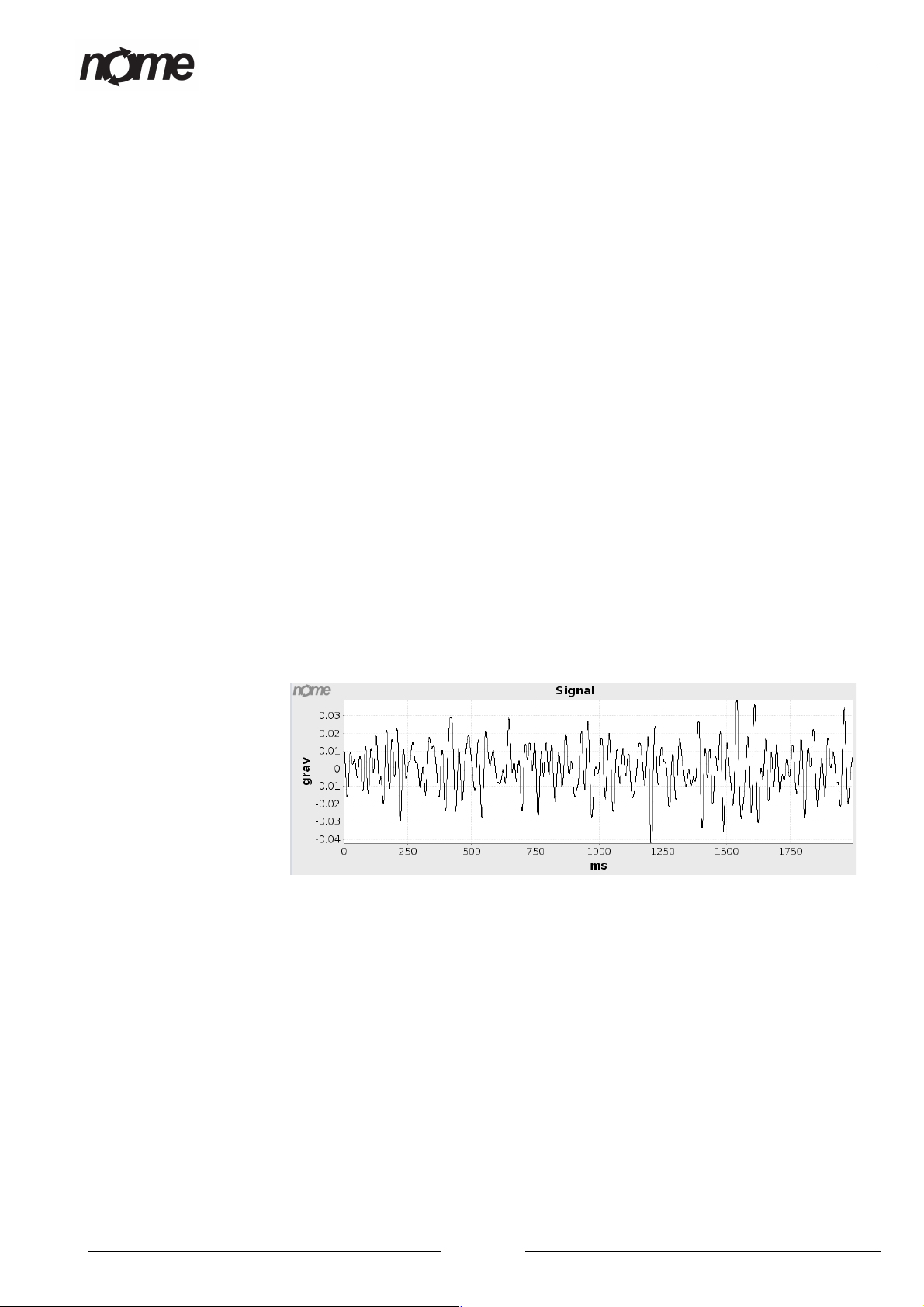
Signal
Some measurement interfaces provide timebase data. This data is described as
signal in nmas. Signal is sample of data during limited time frame. Signal is
used for further analysis and can be stored for later analysis. Signal is typical
for acceleration and voltage inputs.
Picture 1: Signal from acceleration sensor.
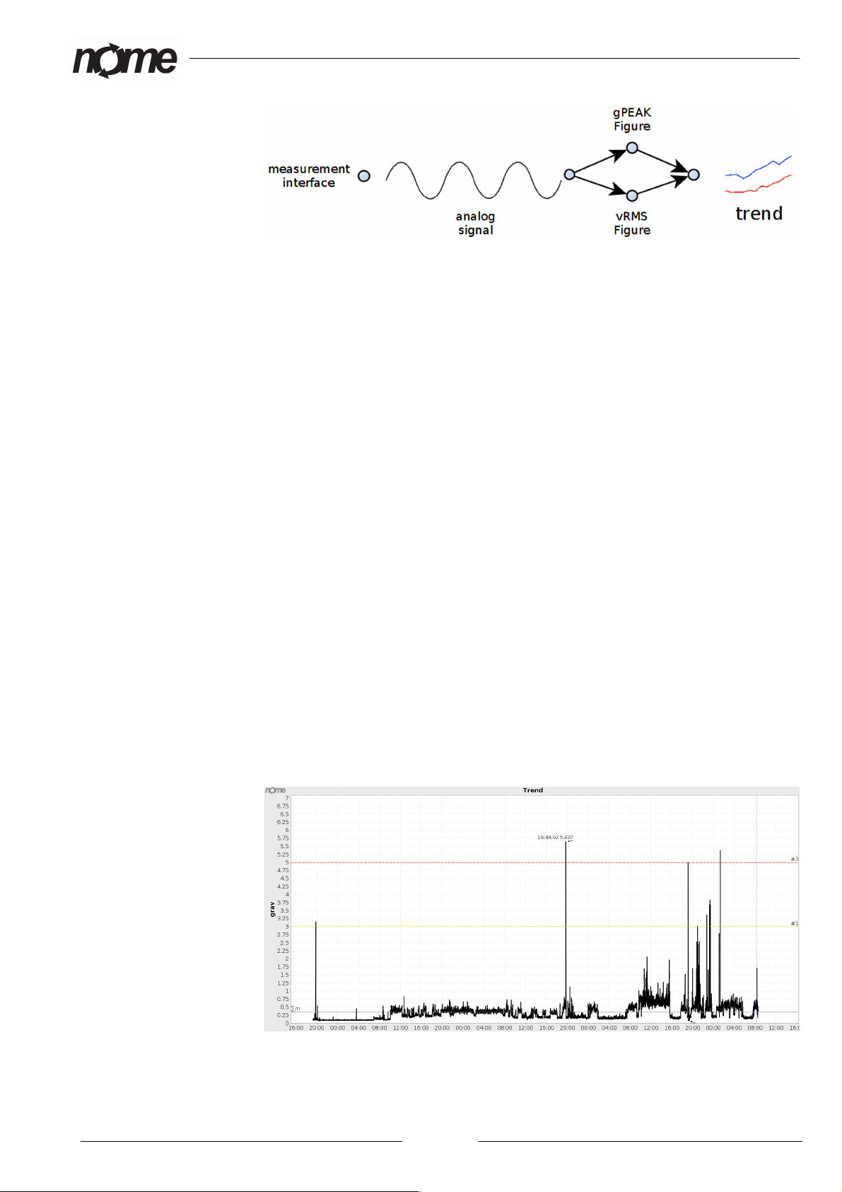
Figure
All trend data is handled as figures. Figures are single number values
representing data from measurement interface. User can attach multiple
figures to same signal. Typically figures have relation to physical quantities.
At least one figure should be linked to every measurement interface. Figure
names are used in data views and reporting.
Page 6
nmas Simple
Picture 2: Figures
Nmas supports figure calculations in two levels. Levels are defined as
hardware level and software level. Difference between levels is that
calculation of hardware level figures are done immediately when data is
measured. Software level figures are calculated when data is stored to
database. Software level figures can also be calculated anytime after data has
been stored.
Nmas hardware level figures can be related to peak, mean or rms values of
relating data. Software level figures have no limitations. Data in nmas storage
can be manipulated, recalculated and associated to other signals as desired.
Please note that some software level figures have to be specially added to nmas
and are not included in standard user interfaces.
Warning and Alarm
Nmas warnings and alarms are always related to figures. All figures can have
individual warnings and alarms. As in figures nmas supports two levels of
warnings and alarms. Levels are defined as hardware level and software level.
When using warnings and alarms it is important to notice that only hardware
level warnings and alarms are calculated immediately when data is measured.
When warning or alarm information demand immediate actions they should be
configured as hardware level warnings and alarms.
Nmas hardware level warnings and alarms can be related to peak, mean or rms
values of data.
Picture 3: Trend data with warning and alarm limit.
Page 7

nmas Simple
Warning and Alarm onfigurations
Warning and alarm configuration allows user to define how warnings and
alarms are treated in measurement hardware and software. Common to all
''warnings and alarms'' is that they have multiple triggering levels. Basic set up
of levels is two. These two levels can be understood as warning and alarm
level.
Passing ''hardware level warnings and alarms'' always triggers data storage. If
action is related to ''figure'' calculated from ''signal'' all related data is also
automatically stored. With this operation user can always verify the reason for
alarm action.
Nmas can be configured to react on every ''figure'' level passing. This is usually
not desired since it can lead to very high amount of data storage. Usually at
least one direction of level passing should be set to values higher than 10. In
typical condition monitoring situation both passing counter values should have
values higher than 10. Due to this behavior data in trend can be higher than
warning or alarm limit without any triggered warning or alarm actions.
Reacting on level passings is controlled with configuration parameters count-
up and countdown. Count-up defines how many times figure value has to be
higher than level before level actions are triggered. Countdown amount defines
how many times figure value has to be lower than set level before level actions
are triggered.
Picture 4: Figure is higher than alarm level in five su sequent measurements and alarm is
triggered with count-up value of five.
Page 8

nmas Simple
Picture 5: Figure is higher than alarm level in three su sequent measurements and alarm is
not triggered with count-up value of five.
Nmas Hardware
nmas Simple
In nmas Simple hardware components Sensor Unit (SU) and Local Data (LD)
are combined in one housing. Other hardware components can be added as
external units.
Nmas Hardware omponents
SU (Sensor Unit)
Sensor Unit (nmas SU) is used to measure data from different kinds of sensors.
Data can be vibration sensor data or data from any other sensor providing
signal between 0 - 30 VDC. Data can be processed inside unit to enable
characteristic value outputs. SU uses Ethernet or radio for communication.
Unit can be configured for different measurements. Configuration is stored in
LD.
LD (Local Data)
Local Data (nmas LD) is a unit to locally store and display measurement data.
LD can store up to 500 MB of measurement data. This is usually more than six
months of measurements.
Data samples from nmas SU are stored as raw signals. Also selected
characteristic values are stored for faster analysis. All raw signals can be
downloaded and processed for more accurate analysis afterwards.
When database is coming to it's size limitations cleaner activates and removes
parts of oldest data.
nmas LD communicates to nmas SU with wired Ethernet or wireless radio
(special orders).
Page 9

nmas Simple
LD can be equipped for remote connections and analysis. Remote connection
can be made via wired or wireless Ethernet.
LD is used as a cloud server for measurement data and software components in
local network.
RD (Remote Display)
Remote Display (nmas RD) is unit to display data in local network. Typical
usage is to present data in control rooms. RD units do not store data. All
visible data is downloaded from nmas-cloud. Data clouds can be in nmas
server or nmas LD. Remote Display can show data from multiple nmas-clouds.
WR (Wireless Router)
Wireless Router (nmas WR) is used for routing data in wireless nmas-network.
Routing can be a combination of Ethernet, wlan or gsm data transfer.
Server
All nmas units can operate individually. Nmas server can be used for central
data storage, long time data storage, remote access, database manipulation and
big data analysis. In small installations nmas server is usually not needed.
Nmas Software
All nmas softwares need Java 7 or higher to run.
nmas Simple software
nmas Simple is shipped with “LD View” and “View” software. nmas Simple
unit is used for hosting “View" software in local network.
nmas RD software
nmas RD is shipped with “View” software.
nmas Server software
Server is used for hosting all software components.
Nmas Software omponents
LD View
nmas LD view software is used to display latest results on small displays. Most
typically LD view software is used on nmas LD unit. Software allows user to
view latest results as a list and a trend. LD View user interface also allows user
to change some values related to measurements.
View
nmas View software is used for viewing data. It can be used for viewing data
in different formats. Basic view is to follow measurements as trend data. nmas
Page 10

nmas Simple
Trend can display also actual signals if they are stored to a database.
Read nmas View manual for more information.
Analysator
nmas Analysator software is used for data analysis. nmas Analysator software
has a wide range of tools for performing analysis for different signals.
Analysator software has been built mainly for analyzing vibration data but can
be used for viewing other time based signals also.
Read nmas Analysator manual for more information.
onfigurator
nmas Configurator software is used for configuring measurements by user.
Read nmas onfigurator manual for more information.
Signal processing
Analog-to-digital converter
Nmas uses AD-converters to convert analog sensor signal to digital format.
Analog-to-digital conversion is done in nmas SU (Sensor Unit). Nmas uses
different conversion rates for high and low frequency signals.
All high frequency signals in one unit are measured at the same time. When
using tacho it is also measured simultaneously with signals.
All high frequency signals are also measured continuously in all channels.
Continuous measurement gives the possibility to trace all phenomena in device
under measurement.
or low frequency signals analog to digital conversion is done channel by
channel. This is generally described as multiplexed measurements. This means
that data from different channels have small difference in time domain.
High and low frequency signals are measured with different AD-converters.
Digital signal processing can be done in hardware and software levels.
Hardware level signal processing is done immediately after the signal is
measured. See chapters “figures” and “warnings and alarms” for more
information.
Typical high frequency signals are vibration, acoustic emission and proximity
signals.
Typical low frequency measurements are temperature and pressure.
High frequency measurement AD-converter
•max number of ADC Inputs: 8
Page 11
nmas Simple
•max conversion Rate: 10 KSPs
•resolution: 24 bit
•SNR: 111 dB
•maximum operating temperature: + 105 C
Low frequency measurement AD-converter
•max number of ADC Inputs: 8 multiplexed channels
•max conversion Rate: Software control
•resolution: 12 bit
•maximum operating temperature: + 105 C
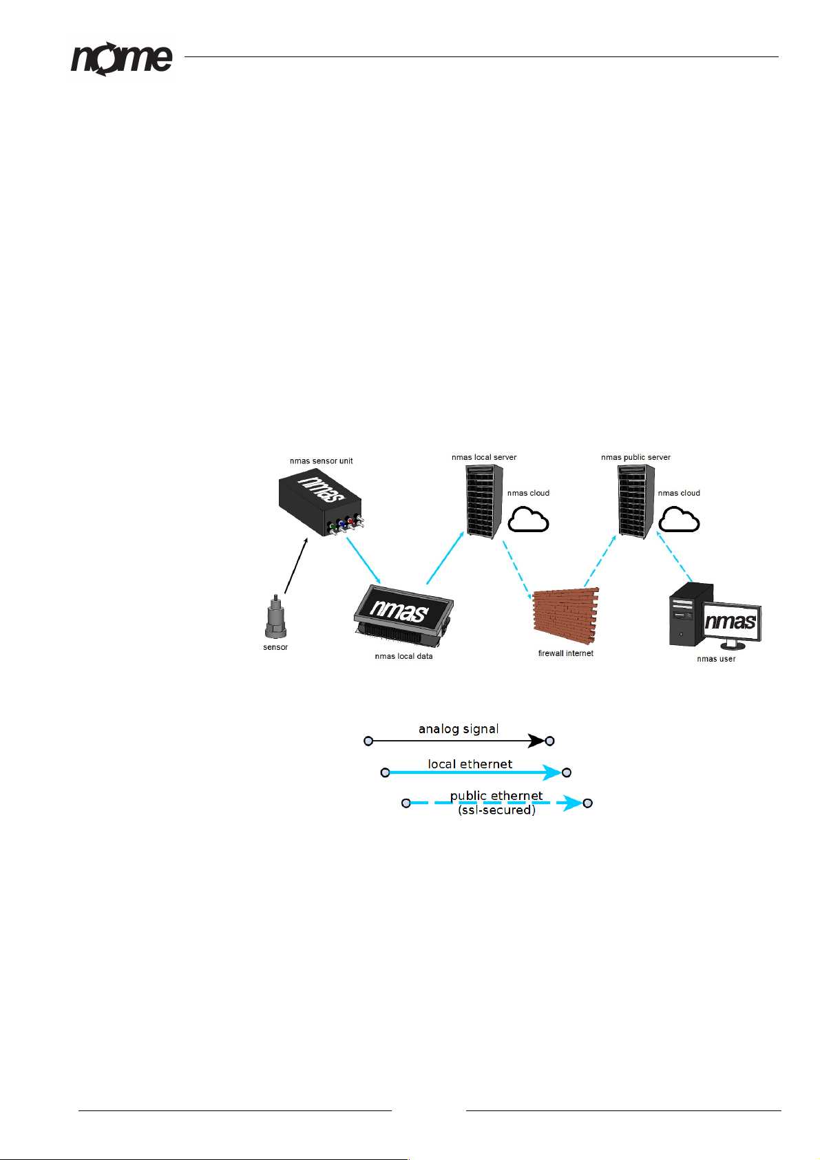
nmas Data Management
Picture 6: Data management in nmas system.
Picture 7: Signal explonations.
Nmas can manage and acquire data on multiple levels. or analog signals first
processing is usually done in nmas sensor unit. Unprocessed analog signal is
usually also send periodically for database storage. Stored values can be used
for analyzing and post-processing.
Digital sensors or serial communication data can be acquired from nmas local
data or nmas server units. Data in nmas cloud can be viewed and recalculated
by user. nmas always stored unprocessed signal. This allows user to use any
recalculation methods available. Server level big data analysis can be
performed in nmas LD and nmas Servers.
Page 12

nmas Simple
Nmas Simple components
•1 piece carrying case
•1 piece nmas Simple unit
•1 piece nmas Simple power cord
•4 pieces acceleration sensors (IEPE 100mV/g)
•4 pieces acceleration sensor cables
•4 pieces magnets for acceleration sensors
•1 piece tachometer with cable
•1 piece adjustable magnetic base for tachometer
•1 piece “nmas user manual”
•1 piece “nmas View user manual”
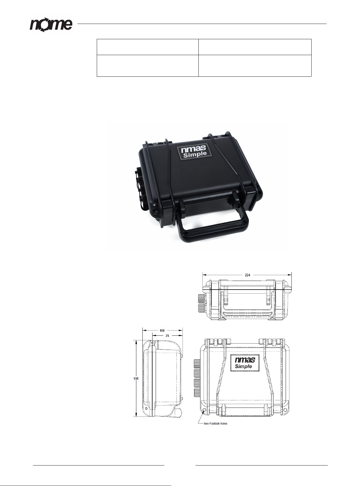
arrying case
Carrying case is used to carry and storage all the components of the nmas
devide. Carrying case is water proof and has custom fitted foams to protect all
the components. It has lockable cliplocks and soft grip handle to carry.
Page 13
Picture 8: nmas carrying case
nmas Simple
IP rating IP 67
Exterior dimensions (L x W x D) 569 x 425 x 215 (22.4'' x 16.73'' x
8.46'')
nmas Simple unit
Small and easy to carry waterproof case with IP 67 rating.
Page 14
Picture 10: nmas simple unit dimensions
Picture 9: nmas simple unit
nmas Simple
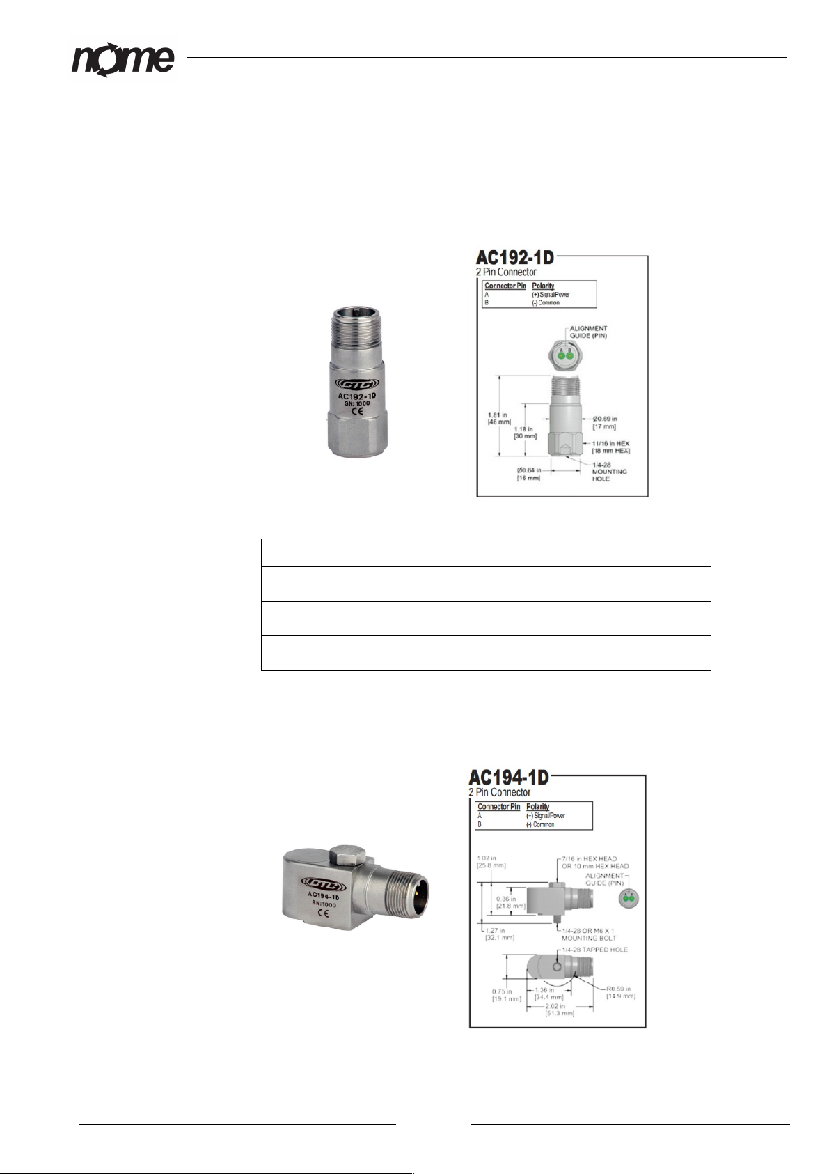
Acceleration sensors
Acceleration sensors provided with nmas device are high quality sensors.
With top exit connector (A 192)
With top exit connector (A 192)
Sensitivity: 100 mV/g
Dynamic range: ± 80 g, peak
Voltage source: 18-30 VDC
With side exit connector (A 194)
Page 15
Picture 12: Accelerometer with side exit connector
Picture 11: Accelerometer with top exit connector
nmas Simple
With side exit connector (A 194)
Sensitivity: 100 mV/g
Dynamic range: ± 80 g, peak
Voltage source: 18-30 VDC
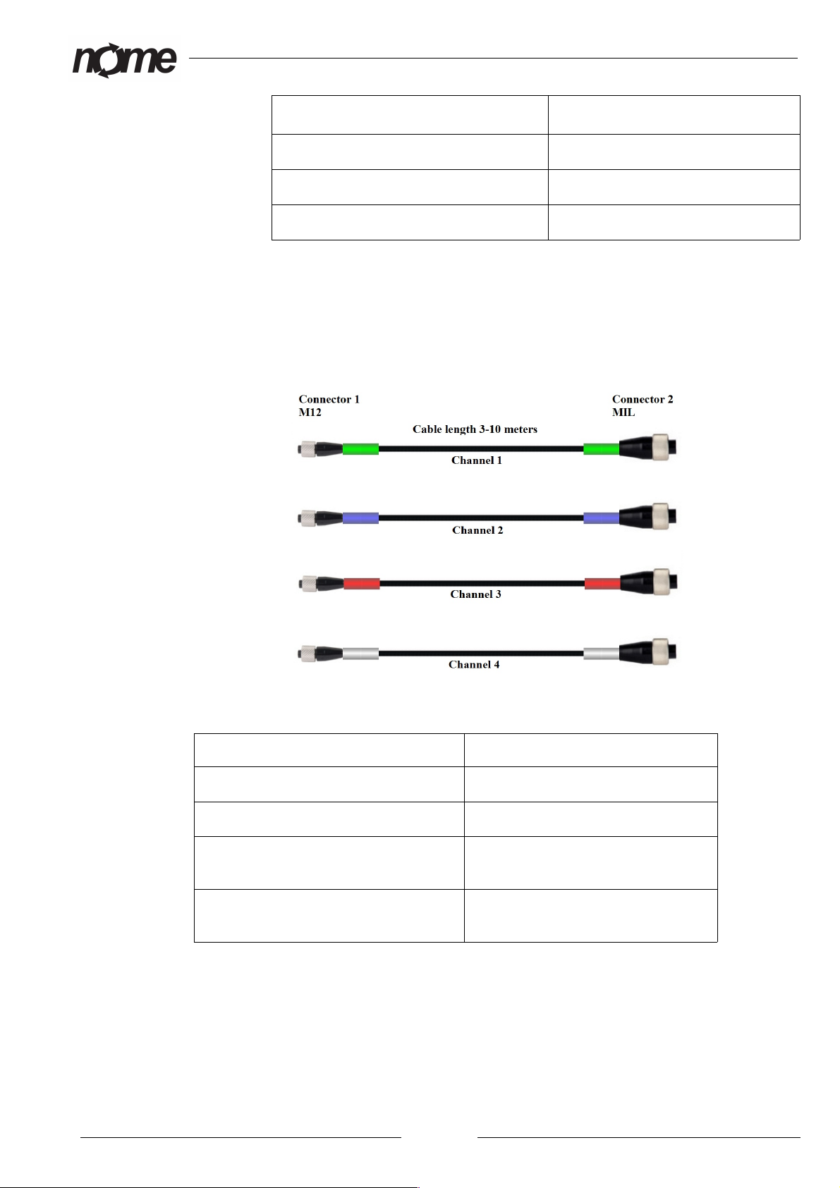
Acceleration sensor cables
All cables provided with nmas device are high quality cables. Cables are color
coded for easy installation.
able material: Black Polyurethane
Max temperature: 121°C (250°)
able diameter: 6 mm (.245 in)
onnector 1: M12-style molded connector with 2
live sockets
onnector 2: MIL-style molded 2 socket
connector
Page 16
Picture 13: Accelerometer sensor ca les
nmas Simple
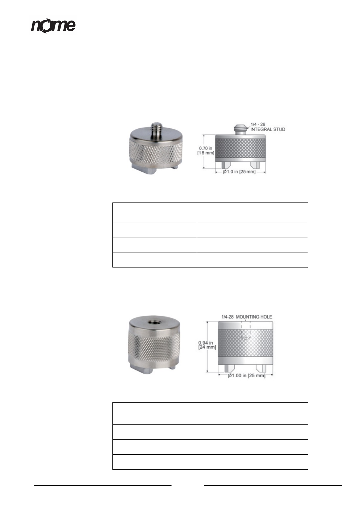
Magnetic base for accelerometers
All the magnetic bases provided with nmas device are high quality rare earth
magnetic bases. Magnetic bases are designed to be used in flat or curved
surfaces.
Magnetic base for top exit accelerometer (MH112)
Base for top exit
accelerometer (MH112)
Pull strenght: 14 kg (30 lbs.)
Mounting: 1/4 – 28 integral stud
Max temperature: 80°C (176°)
Magnetic base for side exit accelerometer (MH128)
Base for side exit
accelerometer (MH128)
Pull strenght: 14 kg (30 lbs.)
Mounting: 1/4 – 28 mounting hole
Max temperature: 80°C (176°)
Page 17
Picture 14: Magnetic ase dor top exit accelerometer
Picture 15: Magnetic ase for side exit accelerometer
nmas Simple
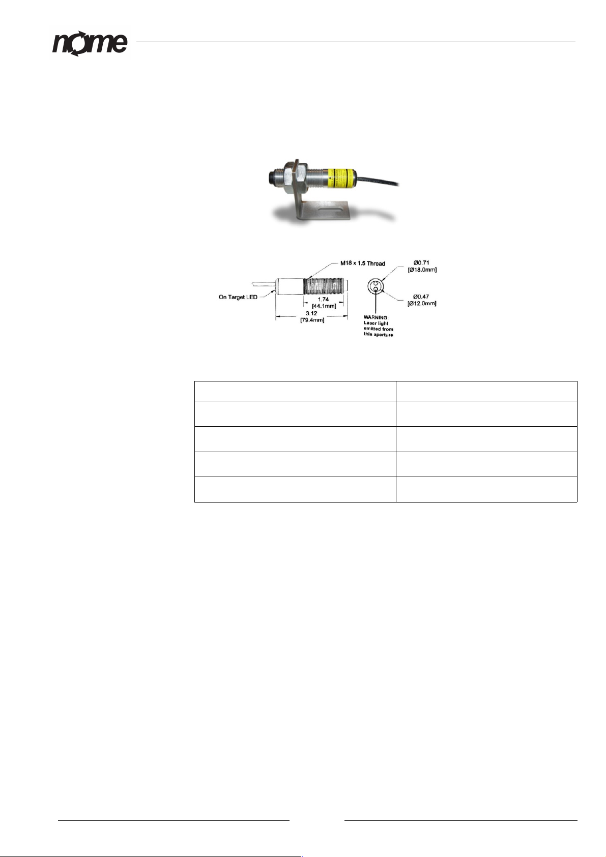
Tachometer (Speed sensor)
Provided tachometer is heavy duty, high quality optical laser sensor. Tacho
comes with a mounting bracket and reflective tape stripes.
Illumination: Visible Red Laser, Class 2
On target indicator: Green led on wire end cap
Operating range: Up to 7.6 meters (25 feet)
Power requirements: 3-15 VDC
Operating temperature: -10°C to 70°C (14° to 158°)
Page 18
Picture 16: Tachometer
nmas Simple
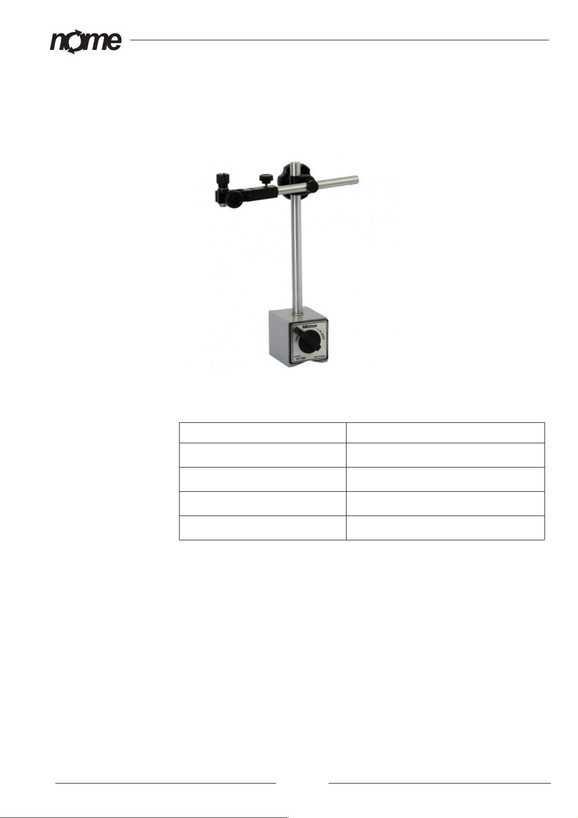
Magnetic base stand for tachometer
With magnetic base stand – user can adjust the right height and angle for the
tachometer. Magnetic base stand has ON/O switch to switch the magnet on
or off.
Holding power: 60 kg
Base size: 60 x 50 x 55 mm
Weigth: 1,4 kg
Vertical arm: 12 mm dia x 170 mm long
Adjustable arm: 10 mm dia x 150 mm long
Page 19
Picture 17: Magnetic ase stand for tachometer
nmas Simple
Preparing for use nmas Simple
Overview
nmas Simple is designed for simple startup and operation. This means unit is
fully functional after connecting sensor and power cables. All cables are
marked with number or color codes for easy installation. Identifier codes are
marked on nmas Simple connection points and both ends of the cables.
Typical ways to access nmas:
•local display (no configuration)
•local nmas_network (no configuration)
•local network (network configuration required)
•remote connetion (no configuration)
•nmas-cloud (no configuration)
Runnning nmas software does not require admin privileges if Java and Java
webstart support is installed. All software is downloaded and run from nmas-
cloud without local installation.
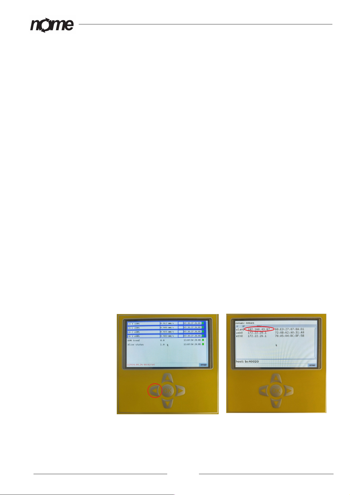
Fast start:
1. Power on nmas Simple, modem and PC
2. Check nmas-Simple IP-address on local display by pressing left
button (wlan0 ip-address)
3. Connect PC to wireless ”nmas_network” with password
”NMAS_Secrets”
4. User web browser on PC to access http://nmas-simple IP-address
Local display
User can access measurements through nmas Simple local display. In local
Page 20
Picture 19: nmas-Simple IP-address
Picture 18: nmas local display
Table of contents
Popular Measuring Instrument manuals by other brands

AEMT
AEMT Time Mark 263 Series manual

Spacetronik
Spacetronik SP-OSM32 user manual

Amprobe
Amprobe THWD-3 user manual

Burkert
Burkert 8026 operating instructions

Network Technologies Incorporated
Network Technologies Incorporated ENVIROMUX-MICRO-TRHP Installation and operation manual

Lutron Electronics
Lutron Electronics LM-8000A manual


