Noncontact meters NCM-603 User manual
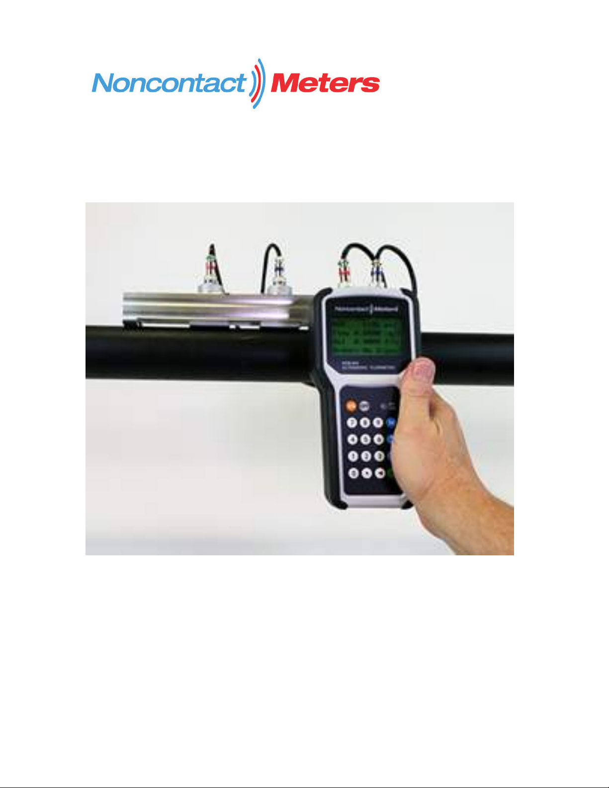
Portable Hand Held Transit Time Ultrasonic Flow Meters
Clamp-On Meter
NCM-603 O&M Rev 07/24/2021User Manual
1

Contents
Quick Start Guide...............................................................................................................................4
1.Introduction.................................................................................................................................... 7
1.1 Preface .................................................................................................................................. 7
1.2Features................................................................................................................................. 7
1.3Principle of Measurement .................................................................................................... 8
1.4 Parts Identification ............................................................................................................... 9
1.5 Typical Applications............................................................................................................11
.............................................................................
............................................................................
1.8 Specifications ......................................................................................................................12
2.Measurement ................................................................................................................................. 13
2.1 Built-in Battery................................................................................................................... 13
2.2 Power On ............................................................................................................................ 13
2.3 Keypad................................................................................................................................ 14
2.4 MenuWindows................................................................................................................... 15
2.5 MenuWindow List............................................................................................................. 15
2.6 Steps to Configure the Parameters ..................................................................................... 16
2.7 Transducers Mounting Allocation ...................................................................................... 17
2.8 Transducers Installation...................................................................................................... 19
2.8.1 Transducer Spacing ................................................................................................. 20
2.8.2 V-method Installation .............................................................................................. 20
2.8.3 Z-method Installation .............................................................................................. 20
2.8.4 W-method Installation ............................................................................................. 20
..............................................................................................
2.9 Installation Checkup........................................................................................................... 21
2.9.1 Signal Strength ........................................................................................................ 21
2.9.2 Signal Quality.......................................................................................................... 21
2.9.3 Total Transit Time and Delta Time.......................................................................... 22
2

2.9.4 Transit Time Ratio .......................................................................................................... 22
3.How To........................................................................................................................................... 23
3.1 How to check if the instrument works properly................................................................. 23
3.2 How to check the liquid flowing direction......................................................................... 23
3.3 How to change units systems ............................................................................................. 23
3.4 How to select a flow rate unit............................................................................................. 23
3.5 How to use the totalizer multiplier..................................................................................... 23
3.6 How to turn on and off the totalizers.................................................................................. 23
3.7 How to reset the totalizers.................................................................................................. 23
3.8 How to restore the factory default setups........................................................................... 24
3.9 How to use the damper to stabilize the flow rate............................................................... 24
3.10 How to use the zero-cutoff function................................................................................. 24
3.11 How to setup a zero point................................................................................................. 24
3.12 How to change the flow rate scale factor......................................................................... 24
3.13 How to use the password locker....................................................................................... 24
3.14 How to use the built-in data logger .................................................................................. 25
3.15 How to use the Frequency Output.................................................................................... 25
3.16 How to use the Totalizer Pulse Output............................................................................. 25
3.17 How to produce an alarmsignal....................................................................................... 26
3.18 How to use the built-in Buzzer......................................................................................... 26
3.19 How to use the OCT output.............................................................................................. 26
3.20 How to modify the built-in calendar ................................................................................ 26
3.21 How to adjust the LCD contrast....................................................................................... 27
3.22 How to use the RS232 serial interface ............................................................................. 27
3.23 How to view the Totalizers............................................................................................... 27
3.24 How to use the Working Timer ........................................................................................ 27
3.25 How to use the manual totalizer....................................................................................... 27
3.26 How to check the ESN ..................................................................................................... 27
3.27 How to check the battery life ........................................................................................... 27
3

3.28 How to charge the built-in battery.................................................................................... 27
3.29 How to calibrate the flowmeter........................................................................................ 27
4.Menu Window Details.................................................................................................................. 28
................................................................................................................................................................
5.Troubleshooting............................................................................................................................. 33
5.1Power-on Errors.................................................................................................................. 33
5.2 Working Status Errors ........................................................................................................ 33
5.3 Other Problems and Solutions............................................................................................ 34
6.Serial Communication .................................................................................................................. 36
6.1 General ............................................................................................................................... 36
6.2 Connect the Flowmeter to a PC ......................................................................................... 36
6.3 Check the Flowmeter COM Port Settings.......................................................................... 36
6.4 Set up PCSoftware............................................................................................................. 36
6.5Communication Protocol..................................................................................................... 37
6.6Protocol Prefix Usage......................................................................................................... 38
6.7The M command andthe ASCII Codes .............................................................................. 39
7. Warranty and Service.................................................................................................................. 75
7.1 Warranty ............................................................................................................................. 75
7.2 Service ................................................................................................................................ 75
7.3 Software Upgrade Service.................................................................................................. 75
8.Appendix........................................................................................................................................ 41
8.1 Battery Maintenance and Replacement.............................................................................. 41
8.2 Transducer Installation Guide............................................................................................ 41
8.3 PipeSize Tables.................................................................................................................. 44
8.4 Sound Speed Tables............................................................................................................ 57
4

NCM-603 Handheld Ultrasonic Flow Meter
Quick Start
Step 1: Power on
Charge the battery fully before using. Press the ON button. The meter will go through a self-
check process. After a few seconds the screen will display information.
Step 2: Program Flow Meter
2.1: Enter transducer info
New purchases or calibrated meters will come programed factory programmed with the
transducer scale factor. If you replace your transducer you will need to update this information.
Press M45, ENT. Key in new scale factor of the transducer, then ENT key again.
2.2: Enter pipe info
Pipe OD: Press keys M11, then ENT. Now enter the pipe outer Diameter, then present ENT key
to confirm.
Wall Thickness: Press the key to scroll down to the next menu, M12. Press ENT, enter the
pipe wall thickness. Press ENT to confirm.
Pipe ID: Press to scroll down to M13. The correct ID value should be displayed. No need to
change.
Pipe Material: Press to scroll down to M14. Press ENT and use the to select the pipe
material. If not shown on the list, select other and refer to the pipe sound speeds in the user
manual and enter the sounds speed. Press ENT to confirm.
Pipe Lining: If your pipe has an internal lining, enter the lining info on menu windows M16-M18.
2.3: Enter Fluid info
Fluid Type: Use the key to scroll down to M20, or press M20. Then press ENT and select the
fluid type. If not shown on the list, select other and refer to the user manual liquid sounds
speeds. Press ENT key to confirm.
2.4: Enter Transducer installation info
Transducer Type: Press to scroll down to M23 or press M23. Press ENT and select the
Standard M1 transducer. Press ENT to confirm.
Mounting Method: Press to scroll down to M24 or press M24. Press ENT and select
transducer mounting and press ENT. For pipe sizes 2” to 12” use the V-Method. For larger pipes
use the Z-Method. You can use the single rail with two transducers for pipe sizes 2” to 6” with
the V-Method. If you use both rails you may need to use the W-Method to accommodate the
transducer spacing. For pipe sizes 12” and larger use both rails and use the Z-Method.
Mounting Spacing: Press to scroll down to M25or press M25. The displayed value is the
mounting spacing between the two transducers.
Step3: Install Transducers
Adjust transducer spacing. Apply acoustic couplant to transducer face. Attach to pipe using
magnets or straps. Attach cables from transducer to handheld flow meter.
5
Step 4: Fine Tuning
Press M90. This will display Transit time ratio – R, Signal Strength-S, Signal Quality-Q.
For optimum performance you should be with the values:
R: 97% ~ 103%
S: 600 ~ 999
Q: 60 ~ 99
If you do not meet the above values, verify the parameters in Step 2. If everything is
programmed correctly evaluate your application and transducer locations. For more details
refer to the User Manual.
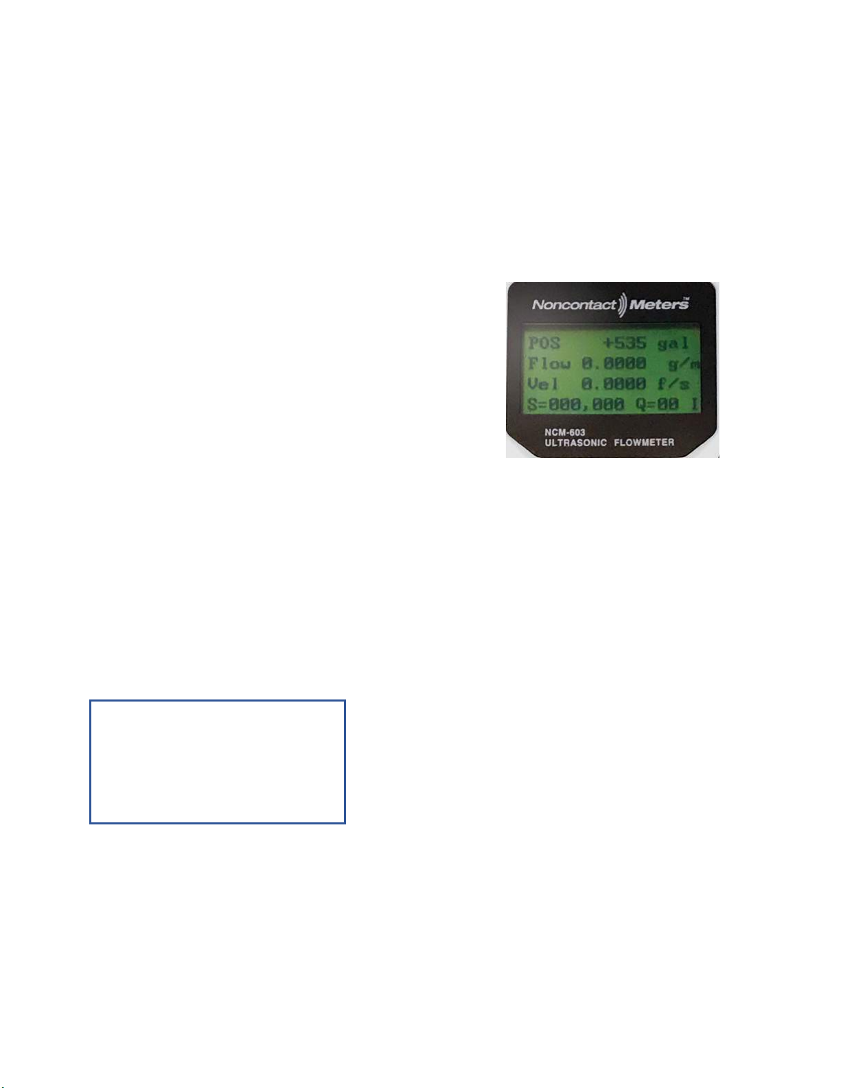
Step 5: Display Flow
Press M1 to return to the main screen that will display
Total, Rate, Velocity, Signal Strength & Quality.
Noncontact Meters Inc
755 Ash St, Canton GA 30114 – USA
Ph (770)516-3999
sales@noncontactmeters.com
www.noncontactmeters.com
NCM-603 Quick Start Rev 7.29.21
6

1. Introduction
1.1 Preface
.
The NCM-603 is based on clamp-on transit-time flow measurement principle. It measures the
flow rate of liquid in a pipe from outside of the pipe by using a pair of ultrasonic transducers. In
general, the liquid should be full in the pipe, and should contain very little particles or bubbles.
Examples of applicable liquids are: water (hot water, chill water, city water, sea water, etc.);
sewage; oil (crude oil, lubricating oil, diesel oil, fuel oil, etc.); chemicals (alcohol, acids, etc.);
waste; beverage and liquid food; solvents and other liquids.
Due to the nature of the clamp-on technique, the transducer installation is simple and
no special skills or tools are required. Besides, there is no pressure drop, no moving parts,
no leaks and no contamination.
The NCM-603 utilizes our proprietary technologies such as advanced signal processing, low-
voltage transmitting, small signal receiving with self-adaptation, etc. It also incorporates the latest
surface-mounting semiconductors and mini PCB design techniques. The built-in rechargeable Ni-
H battery can work continuously for more than 8 hours without recharge.
The NCM-603 also has a built-in data-logger, which allows storage of 2,000 lines of data. The
stored information can be downloaded to aPC through its RS232 connection port with PC
software or Windows HyperTerminal software. The NCM-603 also provides digital output such
as frequency output and pulsed totalizer output.
§1.2 Features
*±0.5%oflinearity
*Accuracy: ±1% of reading in velocity, plus ±0.03ft/s (10mm/s)
*Bi-directional measurement
*4 flow totalizers
*Proprietary low-voltage transmission technology
*Wide pipe sizerange (2”~ 28”)
*Built-in data-logger
*Clamp-on transducer. Easy to install and to maintain
*Optional flow-cell transducer or insertion transducer available for excellent long-term
stability and high accuracy demand
*Lightweight, portable (Main unit 1.2lbs)
*USB interface to computer for easy data download
*PCsoftware
7

1.3 Principle of Measurement
The NCM-603 ultrasonic flowmeter isdesigned to measure the velocity of liquid within a
closed conduit. It uses thewell-known transit-time technology. The transducers are a non-
contacting, clamp-on type. They do not block the flow,thusthere is no pressure drop.They are
easy to install and remove.
The NCM-603 utilizes a pair of transducers that function as both ultrasonic transmitters and
receivers. The transducers are clamped onthe outside ofa closed pipe at a specific distance from
each other. The transducers can be mounted in the V-method where the sound transverses the pipe
twice, or W-method where the sound transverses the pipe four times, or in the Z-method where
the transducers are mounted on opposite sides of the pipe and the sound crosses the pipe once.
The selection of the mounting methods depends on pipe and liquid characteristics.
The NCM-603 operates by alternately transmitting and receiving a frequency-modulated burst of
sound energy between the two transducers and measuring the transit time that it takes for sound to
travel between the two transducers. The difference in the transit time measured is directly and
exactly related to the velocity of the liquid in the pipe, as shown in the following equation and
figure.
Where
θis the angle between the sound path and the flow direction
M is the number of times the sound traverses the flow
D is the pipe diameter
Tup is the time for the beam traveling from upstream the transducer to the downstream
transducer
Tdown is the time for the beam traveling from the downstream transducer to the
upstream transducer
ΔT = Tup – Tdown
downup TT TMD
V
2sin
8
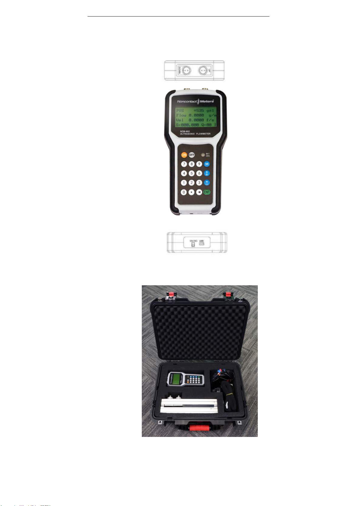
1.4 Parts Identification
Front View
Top View
Bottom View
NCM-603
Complete KIT
with hard carrying case
9

M1-type (2”- 28")
Transducers:
Transducer Cable 5m x 2
RS232C Serial Cable
AC/DC Power and Battery
Charger Adapter
10

1.5 Typical Applications
The NCM-603 flow meter can be applied to a wide range of pipe flow measurements. The
pipe size ranges from 1”-120” (20mm-3000mm). Avariety of liquid applications can be
accommodated: ultra-pure liquids, potable water, oil, chemicals, raw sewage, reclaimed water,
cooling water, river water, sea water, plant effluent, etc. Because the transducers are non-
contacting and have no moving parts, the flowmeter will not be affected by flow pressure or
liquid properties. Standard transducers are rated to 80ºC, and higher temperatures can be
accommodated. For further information, please consult the manufacturer for assistance.
For small pipes, you may choose the flow-cell transducer, instead of the clamp-on transducer, in
order to get better accuracy and better long-term stability.
1.6 Data Integrity and Built-in Time-Keeper
All user-entered configuration values are stored in the built-in non-volatile flash memory that can
retain the data for over 100 years, even when the power is lost or turned off. Password protection is
provided to avoid inadvertent configuration changes or totalizer resets.
A time-keeper is integrated in the flowmeter. It works as the time base for flow totalizing. The time-
keeper remains operating as long as the battery’s terminal voltage is over 1.5V. In case of battery
failure, the time-keeper will not keep running and the time data will lost. The user must re-enter
proper time values after the battery failure is recovered. Improper time values will affect the
totalizers as well as many other functions.
1.7 Product Identification
Each set of the NCM-603 series flow meter has a unique product identification number or ESN
written into the software that can only be modified with aspecial tool by the manufacturer. In
case of any hardware failure, please provide this number, which is located on menu window
M61, when contacting the manufacturer.
1.8 Specifications
Flow Velocity ± 10 m/s (± 32 ft/s), bi-directional.
Physical Quantity Volumetric flow rate, total flow, velocity
Display/Keypad LCD with backlight. 4x16 letters. 4x4 tactile-feedback membrane
keypad. Displays instantaneous flow rate, flow total (positive, negative
and net), velocity, and time.
11

Output Optically isolated Open Collector Transistor output (OCT) for
frequency and pulse.
Recording Automatically records the daily total of the last 128 days, the monthly
total of the last 64 months and the yearly total of the last 5years.
Linearity 0.5%
Repeatability 0.5%
Accuracy* 1% of reading 0.01m/s (0.03ft/s) in velocity*
Response Time 0.5s. Configurable between 0.5s and 99s.
Pipe Size Range 1" - 120" (DN25mm - DN3,000mm), depending on transducer.
Pipe Material All metals, most plastics, some lined pipes.
Rate Units Meter, Feet, Cubic Meter, Liter, Cubic Feet, USA Gallon, Imperial
Gallon, Oil Barrel, USA Liquid Barrel, Imperial Liquid Barrel, Million
USA Gallons. User configurable.
Totalizer Positive totalizer, negative totalizer, net totalizer, and manual totalizer.
Liquid Types Virtually all liquids (full pipe).
Liquid Temperature 32˚F - 176˚F (0˚C - 80˚C) or 32˚F - 312˚F (0˚C - 155˚C), depending on
transducer type
Security Setup lockout. Access code needed for unlocking
Communication
Interface
RS232. Supports the MODBUS protocol.
Software StufManagerTM PC software for data logger download and real-time
data acquisition.
Transducers HS, HM, L1, S1HT, M1HT
Transducer Cable Standard 2x15’ (2x5m), optional 2x30’ (2x10m)
Power Supply 3 AAA Ni-H built-in batteries. When fully charged it will last over 8
hours of operation.
100V-240VAC for the charger
Data Logger Built-in data logger can store over 2,000 lines of data
Manual Totalizer 7-digit press-key-to-go totalizer for calibration
Protection (Handset) IP54
Housing Material (Case) ABS. Aluminum alloy protective case. Suitable for normal and harsh
environments
Handset Size 8”x4”x1.5” (205mmx103mmx37mm)
Carrying Case Size 20"x18"x6" (508mmx457mmx152mm)
Handset Weight 1.2 lbs (514g) with batteries
Package Weight 16 lbs (8kg) for standard package
12

2. Measurement
2.1 Built-in Battery
The instrument can operate either from the built-in Ni-H rechargeable battery, which will last
over 8 hours of continuous operation when fully charged, or from an external AC/power
supply from the battery charger. When the red LED is on, the battery is charging.
The battery-charging circuit employs both constant-current and constant-voltage charging
methods. It has a characteristic of fast charging at the beginning and very slow charging when
the battery approaches to full charge.
Since the charging current becomes tapered when the battery charging is nearly completed
(i.e. the charging current becomes smaller and smaller), there should be no over-charging
problem. This also means the charging progress can last very long. To get close to 100%
power, charge the device overnight. The charger can be connected to the handset all the time
when an around-the-clock measurement is required.
When fully charged, the terminal voltage reaches around 4.25V. The terminal voltage is
displayed on window M07. When the battery is nearly consumed, the battery voltage drops to
below 3V. The approximate remaining working time is indicated in this window as well.
Notice that the battery remaining working time is estimated based on the current battery
voltage. It may have some errors, especially when the terminal voltage is in the range from
3.70 to 3.90 volts.For battery maintenance and replacement, please refer to Appendix §8.1.
2.2 Power On
Press ON key to turn on the power and press OFF to turn off the power.
Once the flowmeter is turned on, it will run a self-diagnostic program, checking first the
hardware and then the software integrity. If there is any abnormality, corresponding error
messages will be displayed.
Generally, there should be no display of error messages, and the flowmeter will go to the most
commonly used Menu Window #01 (M01) to display the Velocity, Flow Rate, Positive
Totalizer, Signal Strength and Signal Quality, based on the pipe parameters configured last
time by the user or by the initial program.
The flow measurement program always operates in the background of the user interface. This
means that the flow measurement will keep running regardless of any user menu window
browsing or viewing. Only when the user enters new pipe parameters will the flowmeter
change measurement to reflect the new parameter changes.
When new pipe parameters are entered or when the power is turned on, the flowmeter will
into a self-adjusting mode to adjust the gain of the receiving circuits so that the signal strength
will be within a proper range. By this step, the flowmeter finds the best receiving signals. The
user will see the progress by the number 1, 2, or 3, located on the lower right corner of the
13
display.
When the user adjusts the position of the installed transducers, the flowmeter will re-adjust
the signal gain automatically.
Any user-entered configuration value will be stored in the NVRAM (non-volatile memory),
until it is modified by the user.
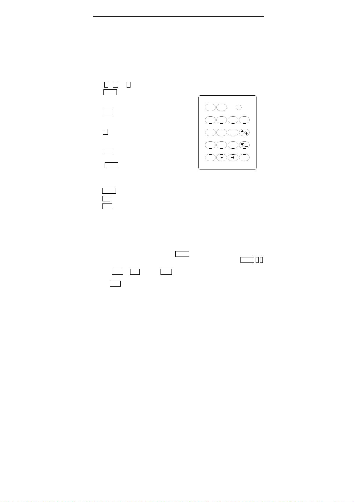
2.3 Keypad
The keypad of the flowmeter has 16+2 keys.
Keys 0 ~ 9 and . are keys to enter numbers.
Key ▲/+ is the going UP key when the user
wants to go to the upper menu window. It also
works as ‘+’ key when entering numbers.
Key ▼/- is the going DOWN key when the user
wants to go to the lower menu window. It also
works as the ‘–’ key when entering numbers.
Key ◄is the backspace key when the user wants
go left or wants to delete the character that is
located to the left of the cursor.
Key ENT is the ENTER key for any input or
selections.
Key MENU is the key for the direct menu
access. Whenever the user wants to proceed to a
certain menu window, the user can press this key
followed by a 2-digit number.
The MENU key is shortened as the ‘M’ key hereafter when referring to menu windows.
The ON key is for the power on.
The OFF key is for the power off.
§2.4 Menu Windows
The user interface of this flow meter comprises about 100 different menu windows thatare
numbered by M00, M01, M02 … M99.
There are two methods to get into a certain menu window:
(1) Direct jump in. The user can press the MENU key followed bya 2-digit number. For
example, the menu window M11 is for setting up pipe outer diameter. Pressing MENU 11
will display the M11 menu window immediately.
(2) Press ▲/+ or ▼/- key. Each ▲/+ key press will lead to the lower-numbered menu
window. For example, if the current window is on M12, thedisplaywill go to window M11
after the ▲/+ key ispressed once.
ENT
CHARGE
MENU
0
4
7
123
5
8
6
9
ON OFF
14

There are three different types of menu windows:
(1) Menu windows for number entering, e.g., M11 for setting up the pipe outer diameter.
(2) Menu windows for option selection, e.g., M14 for the selection of pipe materials.
(3) Results display windows, e.g. window M00 for displaying Velocity, Flow Rate, etc.
For number entering windows, the user can directly press the digit keys if the user wants to
modify the value. For example, if the current window is on M11, and the user wants to enter
219.2345 as the pipe outer diameter, then, the flowing keys should be pressed: 2 1 9 . 2 3 4
5 ENT.
For option selection windows, the user should first press the ENT key to get into option
selection mode. Then, use ▲/+ , ▼/- , or digit key to select the right option. Consequently,
press the ENT to make the selection.
For example, assume your pipe material is stainless steel and you are currently on menu
window M14 which is for the selection of pipe materials (if you are on a different window,
you need press MENU 1 4 first in order to enter into the M14 window.) You need to press the
ENT key to get into the option selection mode. Then, either press the ▲/+ or ▼/- keys to
make the cursor on the line that displays “1. Stainless Steel”, or press the 1 key directly. At
the end, press ENT again to make the selection.
Generally, the ENT key must be pressed to get into the option selection mode for option
modifications. If the “Locked M47 Open” message is indicated on the lowest line of the LCD
display, it means that the modification operation is locked out. In such cases, the user should
go to M47 to have the instrument unlocked before any further modification can be made.
2.5 Menu Window List
M00~M09 windows for the display of the instantaneous flow rate, net totalizer value, positive
totalizer value, negative totalizer value, instantaneous flow velocity, date time,
battery voltage and estimated working hours for the battery.
M10~M29 windows for entering system parameters, such as pipe outer diameter, pipe wall
thickness, liquid type, transducer type/model, transducer installation method, etc.
Transducer installation spacing is also displayed on one of the windows. .
M30~M38 windows for flow rate unit selection and totalizer configuration. User can use these
windows to select flow rate unit, such as cubic meter or liter, as well as to turn
on/off each totalizer, or to zero the totalizers.
M40~M49 windows for setting response time, zeroing/calibrating the system and changing
the password.
M50~M53 windows for setting up the built-in logger.
M60-M78 windows for setting up the time-keeper and displaying software version, system
serial number ESN and alarms.
M82 window for viewing the data totalizer.
M90~M94 windows for displaying diagnostic data. These data are very useful when doing a
more accurate measurement.
M97~M99 are not windows but commands for window copy output and pipe parameter
15

output.
M+0~M+8 windows for some additional functions, including a scientific calculator, display of
the total working time and display of the time and the flow rate when the device
is turned on and turned off.
Other menu windows such as M88 have no functions, or functions that were cancelled
because they were not applied to this version of the software.
The major reason why the menu windows are arranged in the above way is to make this
version be compatible with previous versions. This will make life easier for users of the
former version.
2.6 Steps to Configure the Parameters
In order to make the RH20 work properly, the user must follow the following steps to
configure the system parameters:
(1) Pipe size and pipe wall thickness
For standard pipes, please refer to Appendix §8.3 for outer diameter and wall thickness
data. For non-standard pipes, the user has to measure these two parameters.
(2) Pipe materials
For non-standard pipe material, the sound speed of the material must be entered. Please
refer to Appendix C for sound speed data.
For standard pipe materials and standard liquids, the sound speed values have already
been programmed into the flowmeter, therefore there is no need to enter them again.
(3) Liner material, its sound speed and liner thickness, if there is any liner.
(4) Liquid type (for non-standard liquid, the sound speed of the liquid should be entered.)
(5) Transducer type.
(6) Transducer mounting methods (the V-method and Z-method are the common methods)
(7) Check the transducer distance displayed on window M25 and install the transducers
accordingly.
Example: For standard (commonly used) pipe materials and standard (commonly measured)
liquids, the parameter configuration steps are as following:
(1) Press keys MENU 1 1to enter into M11 window. Input the pipe outer diameter through
the keypad and press ENT key.
(2) Press key ▼/- to enter into M12 window. Input the pipe thickness through the keypad
and press ENT key.
(3) Press key ▼/- to enter into M14 window. Press ENT key to get into the option selection
mode. Use keys ▲/+ and▼/- to scroll up and down to the proper pipe material, and
then press ENT key.
(4) Press key ▼/- to enter into M16 window. Press ENT key to get into the option selection
mode. Use keys ▲/+ and▼/- to scroll up and down to the proper liner material, and then
press ENT key. Select “No Liner”, if there is no liner.
(5) Press key ▼/- to enter into M20 window. Press ENT key to get into the option selection
mode. Use keys ▲/+ and ▼/- to scroll up and down to the proper liquid, and then press
ENT key.
16

(6) Press key ▼/- to enter into M23 window. Press ENT key to get into the option selection
mode. Use keys ▲/+ and▼/- to scroll up and down to the proper transducer type, and
then press ENT key.
(7) Press key ▼/- to enter into M24 window. Press ENT key to get into the option selection
mode. Use keys ▲/+ and ▼/- to scroll up and down to the proper transducer mounting
method, and then press ENT key.
(8) Press key ▼/- to enter into M25 window. The transducer installation distance will be
displayed on the window. Based on this distance, install the transducers on the pipe now.
After installation is completed, press ENT key to go to M01 window to check if the
measurement result is good.
The first-time users may need some time to get familiar with the operation. However, the
user-friendly interface of the instrument makes the operation quite easy and simple. You will
soon find that it is actually very quick to configure the instrument with very little key
pressing, since the interface allows the user to go to the desired operation directly without any
extra steps.
The following tips will facilitate the operation of this instrument.
(1) When the current window is one between M00 to M09, pressing a number key x will
enter into the M0x window directly. For example, if the current window display is M01,
pressing 7 leads to window M07.
(2) When the current window is one between M00 to M09, pressing ENT key will lead to
window M90 for displaying diagnostic data. Press ENT key again to return to the
previous window. Press the . key to go to window M11.
(3) When the current window is M25, pressing ENT key will lead to window M01.
2.7 Transducers Mounting Allocation
The first step in the installation process is to select an optimal location for installing the
transducers in order to make the measurement reliable and accurate. A basic knowledge about
the piping and its plumbing system would be advisable.
An optimal location would be defined as a long straight pipe line full of liquid that is to be
measured. The piping can be in a vertical or horizontal position. The following table shows
examples of optimal locations.
Principles to select an optimal location:
(1) The straight pipe should be long enough to eliminate irregular-flow-induced error.
Typically, the length of the straight pipe should be 15 times of the pipe diameter (15D),
the longer the better.
The transducers should be installed at a pipe section where the length of the straight
pipe at the upstream side is at least 10D and at downstream side is at least 5D.
Additionally, the transducer installation site should be at least 30D away from the pump.
Here D stands for pipe outer diameter. Refer to the following table for more details.
(2) Make sure that the pipe is completely full of liquid.
(3) Make sure that the temperature of the mounting location does not exceed the range for
the transducers.
17

(4) Select a relatively new straight pipe line if it is possible. Old pipe tends to have
corrosions and depositions, which could affect the results. If you have to work on an old
pipe, we recommend you to treat the corrosions and depositions as if they are part of the
pipe wall or as part of the liner. For example, you can add an extra value to the pipe wall
thickness parameter or the liner thickness parameter to take into account the deposition.
(5) Some pipes may have a kind of plastic liner which creates a certain amount of gaps
between the liner and the inner pipe wall. These gaps could prevent ultrasonic waves
directly traveling. Such conditions will make the measurement very difficult. Whenever
possible, try to avoid this kind of pipes. If you have to work on this kind of pipe, try our
plug-in transducers that are installed permanently on the pipe by drilling holes on the pipe
while liquid is running inside.
L up L dn
L up L dn
L up
L up
L up
L dn
L dn
L dn
P
i
p
i
n
g
C
o
n
f
i
g
u
r
a
t
i
o
n
a
n
d
T
r
a
n
s
d
u
c
e
r
P
o
s
i
t
i
o
n
U
p
s
t
r
e
a
m
D
i
m
e
n
s
i
o
n
D
o
w
n
s
t
r
e
a
m
D
i
m
e
n
s
i
o
n
L dn
x Diameters
L up
x Diameters
10D 5D
10D
10D
12D
20D
20D 5D
5D
5D
5D
5D
L up L dn
30D 5D
L up L dn
Piping Configuration and
Transducer Position
Upstream
Dimension
L up
x Diameters
Downstream
Dimension
L down
x Diameters
10D
10D
10D
12D
20D
20D
30D
5
D
5D
5D
5D
5D
5D
5D
5D
18

2.8 Transducers Installation
The transducers used by the NCM-603series ultrasonic flow meter are made of
piezoelectric crystals both for transmitting and receiving ultrasonic signals through the wall
of liquidpiping system. The measurement is realized by measuring the traveling time
difference of the ultrasonic signals. Since the difference is very small, the spacing and
the alignment of the transducers are critical factors to the accuracy of the measurement and
the performance of the system. Meticulous care should be taken for the installation of the
transducers. Steps to the installation of the transducers:
(1) Locate an optimal position where the straight pipe length is sufficient (see the previous
section), and where pipes are in a favorable condition, e.g., newer pipes with ease of
operation and no rust.
(2) Clean any dust and rust on the spot where the transducers are to be installed. For a
better result, polishing the pipe outer surface with a sander is strongly recommended.
(3) Apply adequate ultrasonic couplant (grease, gel or Vaseline)* on to the transducer
transmitting surface as well as to the installation spot on the pipe surface. Make sure
there is no gap between the transducer transmitting surface and the pipe surface.
Extra care should be taken to avoid any sand or dust particles left between the pipe surface
and the transducer surface.
Horizontally lined pipes could have gas bubbles inside the upper part of the pipe.Therefore, it
is recommended to install the transducers horizontally by the side of the pipe.
There are threeways to mount the transducers on to the pipe: by magnetic force, by clamp-on
fixture and by hand. If the pipe material is metal, the magnetic forcewill hold the transducer
on the pipe.Otherwise, you may simply hold the transducer rack and press it against the pipe
if you just need a quick measurement, or, you may use a metal strip or the provided clamp
fixture to install the transducers.
Please see Appendix §8.2 for more installation information.
*Note: It is recommended to use the SOUNDSAFE product from Sonotech, Inc. as the ultrasonic couplant
for safety considerations. Other couplants, such as grease, gel, and Vaseline, can be used as alternatives, but
at your own risk.
2.8.1 Transducer Spacing
The spacing value shown on menu window M25 refers to the distance of inner spacing
between the two transducers (see the following figures). The actual distance of the two
transducers should be as close as possible to this spacing value.
2.8.2 V-method Installation
V-method installation is the most widely usedmethod for daily measurement with pipe inner
19
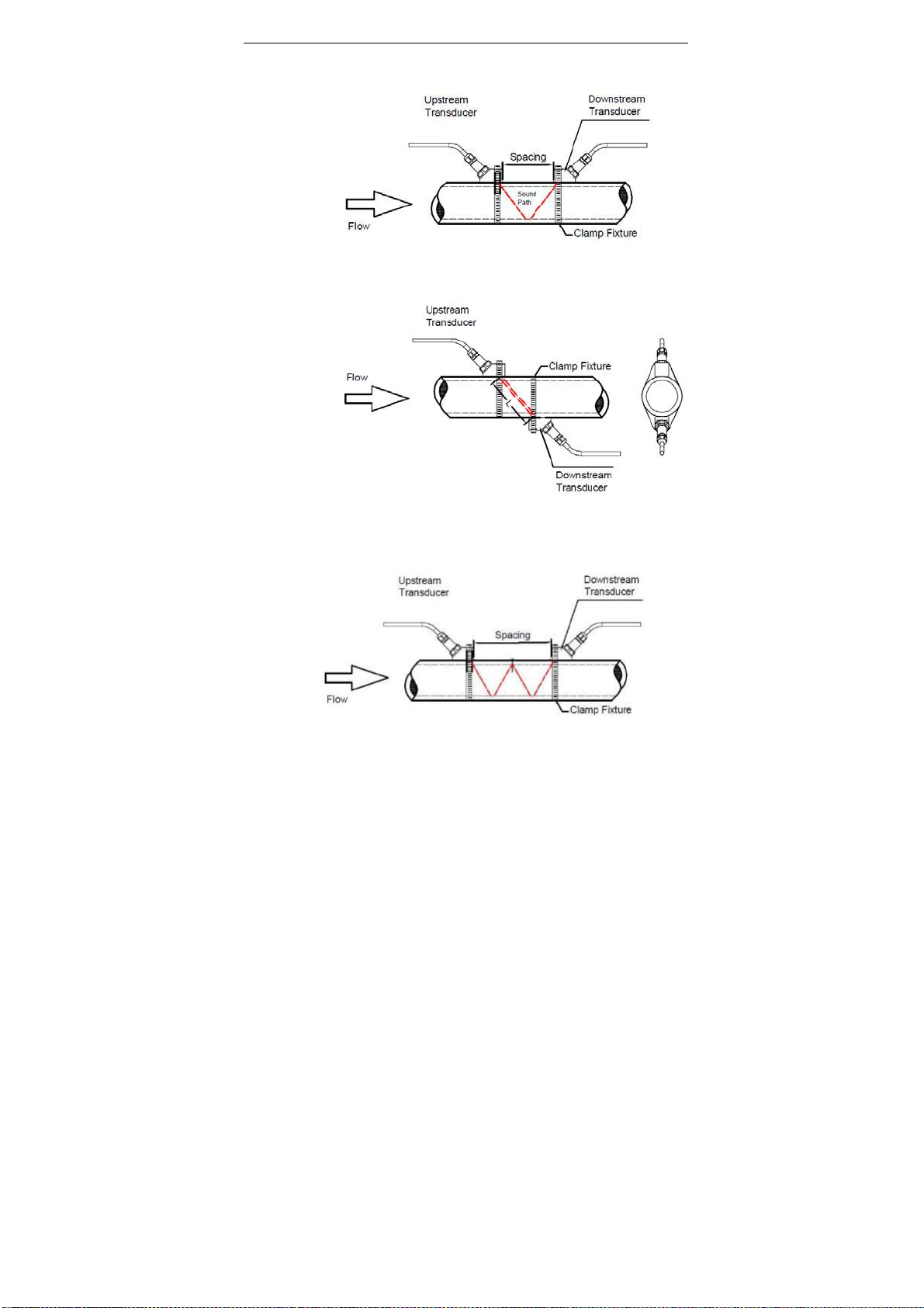
diameters ranging from 25mm (1”) to 400mm (16”). It is also called the reflective method.
2.8.3 Z-method Installation
Z-method is commonly used when the pipe diameter is between 200mm (8”) and 3,000mm
(120”).
2.8.4 W-method Installation
W-method is usually used on plastic pipes with a diameter from 20mm(3/4”)to 50mm (2”).
20
Table of contents
Other Noncontact meters Measuring Instrument manuals

Popular Measuring Instrument manuals by other brands


Arun Microelectronics LTD
Arun Microelectronics LTD PVU3 User instructions

VPInstruments
VPInstruments VPFlowScope VPS.R080.M050 series user manual

S.E. International
S.E. International Sentry manual

Pro's Kit
Pro's Kit MT-7028 user manual

LineEye
LineEye LE-8500X-RT instruction manual

Digi-Sense
Digi-Sense 20250-23 user manual


