6.Coaxial Cable & Continuity Test:
DANGER:
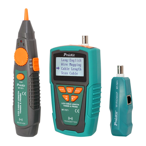
Before testing, please be sure the power of receiver is OFF.
To validate cable shield during cable map tests, do the following as:
1) Connect the Transmitter to the circuit. Connect the test leads
to the coaxial cable to be tested.
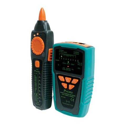
2) Push “ ” button to turn on the power, “POWER/ BAT LOW”
indicator will light up. Push “ ” button on transmitter for
short/ open function, the green LED indicator lights up and the
short/ open testing is working. Push “ ” again, the green
LED lights off and the product is standby for next operation.
3) When “SHORT” red LED indicator lights up, the cable is
connected. (the resistance of cable is less than 300Ω). If the
indicator is off, the cable is short or resistance of the cable is
over 300Ω .
7.Validating Telephone Service and Polarity:
Please follow the following steps to check the polarity of telephone lines:
1) Connect the Transmitter to the circuit. Connect the test leads
to the telephone punch-down blocks, RJ11, and RJ45 jacks.
2) Push button to turn on the power, “POWER/ BAT LOW”
indicator will light up. Then push to operate the polarity
indication feature and the LED indicator will light up. Push the
button again to get the product back to standby status.
3) 「POL-/G,POL+/R」LED indicator is dual color (Red/
Green). The LED indicator of the Transmitter indicates the
status as below:
•Red light:Red test lead at positive (+) polarity;Black
test lead at negative (-) polarity.
•Green light:Red test lead at negative (-) polarity;Black
test lead at positive (+) polarity.
•No Light:Non service or line fault.
8.NCV (Non-Contact Voltage) Testing:
Caution
The feature can be used before locating, isolating, cable mapping to identify if
the tested cable is with AC voltage. It can not only help to ensure the safety of
user and avoid possible electric shock or personal injury, but also protect the
product from being damaged byAC power.
1) Turn the switch to “NCV”, the function is started when the power
indicator is on.


