ATO ATO-DR-WE100 User manual

contents
Automatic setup...........................................................................9
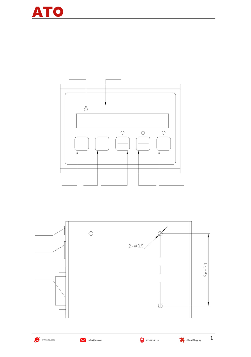
Panel diagram............................................................................... 1
Preset value................................................................................ 4
1. Panel, back panel diagram and button description.............................................1
Score............................................................................................4
Absolute/relative coordinate switching......................................... 3
Counting direction setting............................................................7
2.3
3.7
1.4
2 Basic Operation Instructions............................................................................... 3
1.2
Resolution settings......................................................................6
3.5
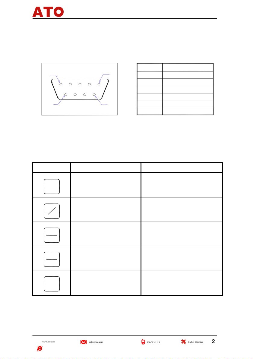
Button description......................................................................... 2
Entering the internal operation parameter function setting.........6
1.1
3.2
Backplane diagram....................................................................... 1
Outbound call operation...............................................................5
Linear compensation setting........................................................8
2.5
Exit internal function settings........................................................9
2.7
Metric/Imperial unit conversion.................................................... 4
3.4
The last two digits of display settings..................................................8
2.4
3.8
Power on...................................................................................... 3
D/R mode setting.........................................................................7
2.1
3.6
Electronic ruler (or magnetic ruler) pin signal................................2
Three internal operation parameter function settings............................................6
Appendix A: Specifications...................................................................................10
2.6
3.1
1.3
3.3

1.1 Panel diagram
1.2 Backplane diagram
WE-100
ZERO
SCALE
EXTERN
POWER
LINEAR
A panel, back panel diagram and button description
Preset/Recall
R/D indicator light
Inc/Abs
Clear Preset/call out
Relative/absolute coordinates
Score
window
English/Metric
1
WE100 manual
ver 2.13
PRESET
ZERO
MM
INCH
HALF
Window
ZERO ABS
INC
Inch/mm
R/D LED
1/2
DIA
1

1.3 Electronic ruler (or magnetic ruler) pin signal
1.4 Button description
5-8
0V
3
FG
+5V
2
NC
9
1
A
4
96
1
5
1
INCH
INC
MM
2
ABS
WE100 manual
ver 2.13
No.
Foot number
The display value switches between metric/imperial system
and increases the number by 1 when presetting the number.
ZERO
Score
INC/ABS coordinate mode switching shifts
to the left when presetting the number
Divide the displayed value by 2
and use it as a sign when presetting the number
key symbol
Imperial/Metric units
Description:
Clear the displayed value to zero
and use it as the cancel key when setting and presetting the
number
preset /call out
internally.
Relative/absolute coordinate mode
The preset/recall operation is a
confirmation key when setting the internal settings and
preset numbers.
Function
B
Reset
PRESET
2

2. Basic operating instructions
Function introduction: Turn on the POWER, and the digital display enters the self-test state.
Function introduction: When the digital display is in normal display state, the displayed value is cleared to zero.
Operation steps:
key to complete the
Operation steps:
switch.
(3) After clearing, if the electronic ruler (or magnetic ruler) has not moved and other keys have not been pressed, you
After completion, the various states of the last shutdown will be retained (including position,
Function introduction: The coordinates are between "ABS" (absolute coordinates) and "INC" (relative coordinates) switch between.
coordinate mode, display unit, indicator light, parameter setting value, etc.)
can
press again
At zero, the ABS mode value does not change.
key to cancel clearing and restore to original value.
Note:Whenthelightison,itmeansthatthecoordinatemodeis"INC" (relativecoordinates).
(2) When cleared in ABS mode, the value in INC mode is also cleared at the same time; while cleared in INC
key, clear.
Note : (1) INC and ABS can be cleared in both states.
mode
INC
ABS
2.1 Power on
2.3 Absolute/relative coordinate switching
2.2 Clear
WE100 manual
ver 2.13
ZERO
ZERO
according to
press
3

2.6 Preset values
2.5 points
2.4 Conversion of metric/imperial units
INCH
MM
1
2
2
1
ZERO
PRESET
1) Press and hold
Operation steps:
Operation steps:
For about 3 seconds, the window displays the current value of the electronic ruler (or magnetic ruler),
key; (To prevent misuse
and
Using this function, the zero point can be set at the center of the workpiece.
Function introduction: The unit of display size is switched between "MM" (metric system) and "INCH" (imperial system).
button to restore to the state before splitting)
1) Aim the edge finder at one side of the workpiece and press
press again
3) Move the edge finder and find the point with a displayed value of 0.000, which is the center of the workpiece.
key;
2) Movetheedgefindertotheothersideoftheworkpieceandpress
Function introduction: When the digital display is in normal display state, preset the display value of the current position. Example: Preset-125.455
Operation steps:
Function introduction: Divide the displayed value by 2.
ver 2.13
WE100 manual
Note: This function can only be used in INC mode.
key to complete the switch.
Note: When the light is on, it means that the unit of the displayed size is "INCH" (imperial system).
according to
4

The light above the key lights;
key to call out the preset value. At this
time
key to exit.
5) Use the above method to input the value of each digit.
2) The
flashing number of the button increases by 1. When the number is 9, it becomes 0 (when the
flashing number is the last digit,the value increment is related to the current resolution).
4) Press the button. If it was originally a positive number, the current value will become a negative number. Otherwise, if it
was originally a negative number, it will become a positive number.
2) To prevent misoperation, you can press it again
6) Press the
Function introduction: call out the preset value.
Operation steps:
key to cancel the call.
3) Press
the
button once to go to the rightmost position.
1) Press
WE100 manual
Thelastdigitflashestoindicatethatithasenteredthepresetmode.
The key flashes and moves one position to the left. If it moves to the highest position, press it again.
key,thedefaultvaluewillbestoredandexit;orifthedefaultvalueisnotstored,then
PRESET
PRESET
PRESET
PRESET
Note:1)ThepresetvalueoperationcanonlybeperformedintheINCstate.
2)
The decimal point position always remains unchanged and is related to the resolution of the current axis.
Note: Outbound calls can
only be made in the INC state.
2.7 Outbound call operation
ABS
2
INC
ABS
1
INCH
INC
ver
MM
2.13
ZERO
according to
Press the
5

ZERO
ZERO
WE100 manual
ver 2.13
You can switch between setting parameter items by pressing Change parameter values.
Note: Press
Three internal operating parameter function settings
3.2 Resolution setting
3.1 Enter the internal operation parameter function setting
Resolution settings
Set the electronic ruler (or magnetic ruler) resolution.
QUIT
key. After the self-test is completed, the window will display
AUTOSET
L
Exit settings
After turning on the power, when the digital display box performs
self-test, pressing "UNIT 1" indicates that it has entered the internal function settings.
key until the window displays "unit 1";
Automatically set
ikB
2) Press
Linear compensation setting
dir
rA
Last two digits display settings
Electronic ruler (or magnetic ruler) counting direction setting
unit
1) Enter the internal function settings;
Operation steps:
Parameter content:
D/R mode setting
PRESET
MM
INCH
6

INCH
MM
INCH
MM
INCH
MM
3.4 Counting direction setting
3.3 D/R mode setting
3) Press the button to switch between resolutions. The options are 0.5ÿm, 1ÿm, 5ÿm, 10ÿm, 50ÿm, 100ÿm, 500ÿm,
1000ÿm, etc. The factory setting value is 1ÿm.
1) Enter the internal function settings;
Operation steps:
Until the window displays "dir 0";
key to select the counting direction of the electronic ruler (or magnetic ruler). 0 and 1 directions
Operation steps:
Set the counting direction of the electronic ruler (or magnetic ruler).
Until the window displays "rA 0";
2) Press
Set the position of the electronic ruler (or magnetic ruler) to be displayed in R mode (radius mode) or D mode (diameter
mode). The D mode display value is twice the R mode display value.
2) Press
3) Press the
opposite direction, the specific direction will be determined during installation. The factory setting value is 0.
3) Press the button to select R mode or D mode. 0 means R mode, 1 means D mode. The factory setting value is 0,
which is R mode.
1) Enter the internal function settings;
ver 2.13
WE100 manual
ZERO
ZERO
7

3.5 The last two digits display settings
3.6 Linear compensation setting
ZERO
ZERO
3) Press
the button to select the display mode. 0 indicates that the last two digits are displayed, 1 indicates that the last digit
will become a positive
5) If the button was originally a positive number, the current value will become a negative number. On the contrary, if the button was originally a negative number, the
current value
number.
2) Press until the window displays a five-digit value. If it is all zero, it means there is no compensation. Otherwise, the
compensation value is set to this value; that is, "LL". The last L represents the current linear compensation value,
and
the
last digit flashes and waits for the input value. |
Until the window displays "bL 0";
Move the key one position to the left. When it moves to the highest position, move it further left to the rightmost position.
4) Press one
digit on the side.
2) Press
1) Enter the internal function settings;
Operation steps:
Set the linear compensation value of the electronic ruler (or magnetic ruler).
1) Enter the internal function settings;
The key flashes and the number increases by 1. When the number value is 9, it becomes 0.
Operation steps:
Set whether the last two digits of the data in the window are
is not displayed, and 2 indicates that the last two digits are not displayed. The factory setting value is0.
displayed.
3) Press
WE100 manual
ver 2.13
INC
MM
MM
INCH
ABS
2
INCH
1
8

ZERO
ZERO
ZERO
ZERO
ÿ
ÿ
Compensation value
PRESET
PRESET
Save and exit internal function settings.
Note: After the system is automatically set, all setting items are set to 0.
2) Press to store the
setting value and leave the internal function setting. (Press back to internal
Key weight function settings)
2) Press until the window displays "AUTOSET". At this time, press
the automatic setting, and the window displays "Init_EE". After completion, it will automatically switch to the next setting item.
2) The compensation value is calculated according to the following formula:
Standard
Display value-Standard value x1000000
value
key until the window displays "QUIT".
-99999.
1) Press
Note: 1) The maximum input compensation value shall not exceed 99999, and the minimum value shall not be less than
1) Enter the internal function settings;
Operation steps:
Save the entered value and exit setting the compensation value.
Set the system to factory settings.
6) Press
Operation steps:
WE100
manual
ver 2.13
3.7 Automatic settings
3.8 Exit internal function settings
the key to confirm
9

104*77*35(mm)
252.5g
DC 7.5~9V
weight:
Power
supply:
Power consumption: Electronic interface: TTL
<5W
size:
WE100 manual
ver 2.13 10
Appendix A: Specifications
Table of contents
Other ATO Measuring Instrument manuals
Popular Measuring Instrument manuals by other brands

Digital Control Incorporated
Digital Control Incorporated DigiTrak LT Operator's manual

Hanna Instruments
Hanna Instruments HI99151 instruction manual

LaMotte
LaMotte WaterLink Spin manual

Xylem
Xylem Multi 3620 IDS operating manual

edc
edc MU300 user manual

Brooks Instrument
Brooks Instrument GT 1305 Installation and operation manual