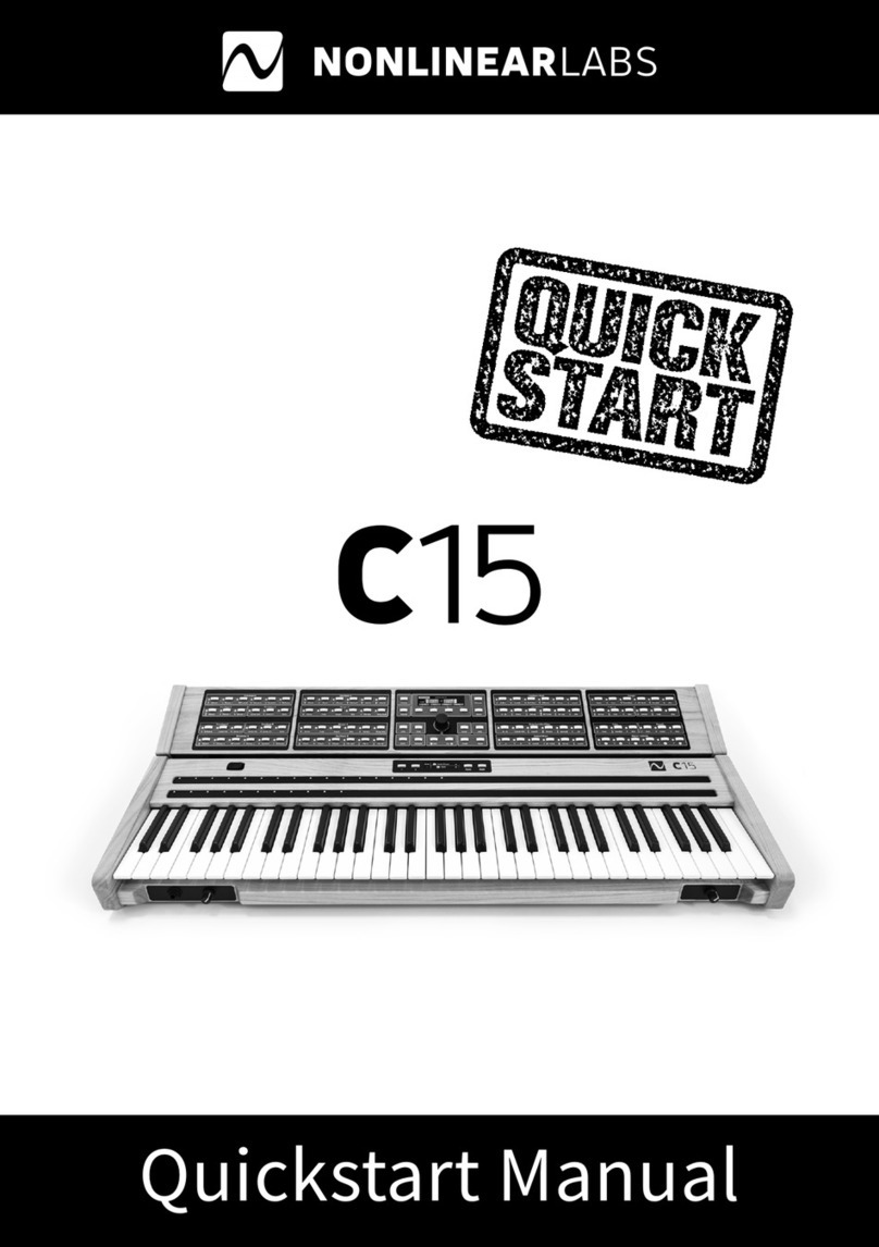
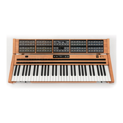
NONLINEAR LABS C15 Installation and operating instructions

User Manual Addendum
Update 2020-12

NONLINEAR LABS GmbH
Helmholtzstraße 2-9 E
10587 Berlin
Germany
www.nonlinear-labs.de
info@nonlinear-labs.de
Author: Matthias Seeber
© NONLINEAR LABS GmbH, 2020, All rights reserved.

Addendum - 2020-12
Addendum - 2020 - 12
4 5
Enable (On, O): When on, only one note (containing the defined number of Unison
Voices) will be playable, even when multiple keys are pressed. As long as one key stays
pressed, the release of a key will not stop the envelopes.
ࠎNote that changes to Mono Enable will reset held keys.
Priority (Lowest, Latest, Highest): When hitting multiple keys, they are sorted by the
chosen priority. Keys matching the chosen priority determine the pitch of the Mono voice.
When releasing the priorized key, the pitch will be determined by the key with second
closest priority match.
Glide Time (0 ms ... 16000 ms): This time can be used to create a portamento by smooth-
ing the transitions of the pitches. Depending on the Legato options the smoothing is
applied to each pitch change or only when the keys are played in “legato” style (in an
overlapping manner).
Legato (None, Envelopes, Glide, Env & Glide)
None: No dierence between legato and non-legato playing. The envelopes will
be retriggered by every key-down and the Glide parameter will be applied to every
pitch step.
Envelopes: The envelopes will be retriggered only by key-downs that are played
non-legato. The Glide parameter will be applied to every pitch step.
Glide: The Glide parameter will be applied only to keys that are played legato. The
envelopes will be retriggered by every key-down.
Env & Glide: The envelopes will be retriggered only by key-downs that are played
non-legato. The Glide parameter will be applied only to keys that are played legato.
In Layer Sounds the Mono settings are applied to both Parts.
Mono Presets are marked with a “”
symbol or “
” in the Graphical UI.
Unison Presets have a “” symbol or “�” in
the Graphical UI.
Presets that combine both voice modes are
marked ““ or “
“.
Major Parameter Enhancements
In the following, major changes and enhancements to parameters are explained.
For a complete list of new, enhanced and relocated parameters, see Detailed Parameter
Changes.
Master Volume, Master Tune and Scale
On the Sound screen So Button 4 (Mas-
ter..) opens the Master Parameter screen.
The Volume and Tune parameters are now
modulateable, so the Master Volume could
still be instantly accessable when using a
Macro Control.
Unison
On the Sound screen So Button 3
(Voices..) opens the Voices screen.
The Unison parameters are displayed there.
To change them press So Button 4
(Unison..). It opens the Unison Parameter
screen. The maximum number of Unison
Voices is now 24 for Single Sounds and 12
for a Layer Sound or a Part of a Split Sound.
In Layer Sounds the Unison settings are
applied to both Parts.
ࠎNote that changes to the Unison Voices will reset held keys.
Mono
On the Sound screen So Button 3
(Voices..) opens the Voices screen. There
you find a display of the Mono parame-
ters. To change them press So Button
2(Mono..). It opens the Mono Parameter
screen.

Addendum - 2020-12
Addendum - 2020 - 12
6 7
Part Volume and Tune
In Split and Layer Sounds, the Volume and
Tuning of a Part can be adjusted by its Part
Volume and Part Tune parameters.
The stereo signals of both Parts are mixed before the Master Volume control. The Master
Tune is added to the two Part Tunes.
When a Single Sound is converted to a Split or Layer Sound, its former Master Volume
and Master Tune will be copied to its Part Volume and Part Tune while Master Volume and
Master Tune are set to zero. When a Single Sound is loaded into a Split or Layer Sound,
its former Master Volume and Master Tune will also be copied to its Part Volume and Part
Tune but Master Volume and Master Tune stay unchanged.
When a Part of a Split or Layer Sound is converted to a Single Sound, the Master Volume
and Master Tune values are summed up with Part Volume and Part Tune to create the
Master Volume and Master Tune of the Single Sound.
Furthermore, the delegation of the Master Volume/Tune to the Part Volume/Tune param-
eters also includes potential assignments to Macro Controls.
In Dual Sounds, the Part Volume/Tune is designed to serve as the potential Master, should
the Part get converted as a Single Sound again.
In order for this to work properly, we recommend not to create Macro Control assign-
ments to Master Volume/Tune within Dual Presets. Or to be more precise: these assign-
ments will be discarded, when converting a Dual Preset back to Single.
Reset
The new “Reset” parameter of the Oscilla-
tors (accessed via the “Phase” Parameter
Selection button) can be set to “O” to avoid
glitches caused by the oscillator phases
being reset at key-down. They become noticeable if the Release phase of the Envelopes is
longer than the time between two notes. Without the phase reset the Oscillators are “free-
running” and the Phase parameter has no influence on the start phase. This will also aect
the sound of unison voice stacks and will eectively disable the Unison Phase parameter.
Macro Controls
6 Macro Controls
Macro Control E and F have been added.
Smoothing Times of the Macro Controls
In former soware versions these smoothing times didn’t have an eect. Instead the
Edit Smoothing Time (typically 20 ms) from the Device Settings was used. For backward
compatibility please make sure that a similar smoothing time is now set for each of the
Macro Controls.
MC Target Overview
When a Macro Control is selected, all
assigned target parameters will show their
assignment by blinking LEDs.
This applies to parameters that are avail-
able on one of the Parameter Panels.
MC Target Indicators
Assigned parameters not available on any
Parameter Panel are indicated by literal
symbols in the Macro Control screen.
Name / Type Remarks
MIndicates assignments to Master Volume or Master Tune.
uIndicates an assignment to Unison Detune. In a Split Sound, the Part in
focus is reflected.
mIndicates an assignment to Mono Glide. In a Split Sound, the Part in focus
is reflected.
PIndicates assignments to Part Volume, Part Tune (in Split or Layer Sounds)
or the Split Point (only in Split Sounds).
Comb S.V.F. Eects Reverb Drive Level
Feedback Mixer
Macro Controls

Addendum - 2020-12
Addendum - 2020 - 12
8 9
→Graphical UI
When a Macro Control is selected, it will be
surrounded by a red rectangle. All assigned
target parameters show their assignment
by surrounding red rectangles as well.
In Split or Layer Sounds, the Part in focus is
reflected.
Key Range Enhancements
In earlier versions, the C15 only operated on its physical key range of 61 keys (C1 ... C6).
The Hardware UI Note Shi was applied as a tuning, whereas Split Point and Fade From
or Range parameters were bound to the physical key range, eectively ignoring the Note
Shi.
Polyphonic Key Pan in the Output Mixer was also bound to the physical key range, also
eectively ignoring the Note Shi.
With this static behavior of key ranges on polyphonic Part association, fade level and
panning, it became apparent that there are limitations.
In this version, a virtual key range of 128 keys (C-2 ... G8) was added. The physical key
range of 61 keys is now projected onto the virtual key range, depending on the Note Shi
(which is now a real key shi and not a tuning anymore).
Extreme Note Shi may exceed the virtual key range for certain keys, in which case no
note is produced.
Split Point and Fade From or Range parameters now operate within the virtual key range
and the Note Shi can be used to transpose into or out of Parts. The parameters still can
only be set within the physical key range (C1 ... C6) - which will be addressed by a future
update.
Polyphonic Key Pan in the Output Mixer now also operates within the virtual key range
and the Note Shi can be used to transpose into or out of more extreme panning. At
100%, the panning starts to clip at the physical key range’s edges (C1 ... C6), at 47.24 % the
panning covers the whole virtual key range (C-2 ... G8).
See Diagrams for more info.
Sound Types
Overview
In earlier versions the C15 only supported
“Single” Sounds, where all voices are con-
trolled by the same set of parameters. Now
“Split” and “Layer” Sounds are available
consisting of two “Parts” (I, II). Each Part
can use up to 12 voices based on its own
parameter set.
In Split mode the Parts are assigned to two
separate keyboard ranges. Part I can be
played between the lowest key (C1) and the
Split Point, Part II between the Split Point
and the highest key (C6). The Parts have
separate voice allocations, which means
that they can have dierent settings for
Mono and Unison. The Split Point is not
aected by Master Tune or Part Tune.
In Layer mode each voice of Part I will be
played simultaneously with the corre-
sponding voice of Part II. Both Parts share
the same voice allocation, which means
that they have identical settings for Mono
and Unison.
ࠎNote that held Keys will reset when loading whole Presets or Parts of dierent types.

Addendum - 2020-12
Addendum - 2020 - 12
10 11
Split Sound Details
Adjusting the Split Point
On the Split Sound screen the Split Point
is shown in the center. It can be edited
directly by the Encoder and the Dec/Inc
buttons. If Part I is selected it shows the
highest key of the lower key range. If Part
II is selected it shows the lowest key of the
upper key range. The Split Point is also
available as a parameter in the Part screen.
Use So Button 2 (Part..) to open the Part
screen.
Here the third parameter is the Split Point.
The Split Point parameter can be controlled
by a Macro Control. As Hardware Source
a ribbon will make a lot of sense. The Part
association of individual voices happens
only when a key is pressed, according to
the current value of the Split Point.
→Graphical UI
In the Graphical User Interface, the Sound
tab provides the Split Point between the
two parts. Use drag gestures in order to
change it.
In addition, the Part group (le to the
Master group) provides the Split Point as a
regular parameter, which can be manipu-
lated further in the Parameter tab.
Overlapping Splitpoints
In earlier versions, the C15 only provided one Split Point parameter in a Split Sound,
determining the inner edges of both fully separated Parts, so no overlap was possible.
The described behavior is still available by default and referred to as “linked” Split Points.
Now, “unlinked” Split Points are available as well, providing separate Split Points for each
Part (but still sharing one unique Macro Control assignment).
When unlinked, an overlapping range of shared keys can be defined, in which both Parts
will sound. The two Split Point parameters are still sticked to one another, preventing a
negative overlap with a key range with no Part association.
The linking behavior can be changed by the Edit button:
When in the Parameter screen, pressing
Edit will provide a menu with the option to
Unlink/Link. Navigate with So Button 4
for the entry before pressing Enter.
When unlinked, the key positions of both
Parts are shown. Overlap can be achieved
by raising the Split Point of Part I or by
lowering the Split Point of Part II - using the
Inc/Dec buttons or the Encoder.
When in the Sound screen, pressing Edit
will provide a menu screen. Navigate by
Inc/Dec or the Encoder to the “Link Split-
points” option and press Enter to toggle
between the two behaviors.
When unlinked, the key positions of both
Parts are shown.
ࠎEnabling a linked Split Point will collapse any prior overlapping range.

Addendum - 2020-12
Addendum - 2020 - 12
12 13
→Graphical UI
In the Parameter tab, an icon on the right of the shown key position indicates the linked
or unlinked Split Point behavior. Clicking on it will toggle inbetween.
In the Sound tab, clicking on the “...” icon on the right invokes a menu in which the linking
behavior can be set.
→Split Point Editor (Graphical UI only)
In the Sound tab, the rightmost icon redirects to the Split Point Editor, providing the two
parameters and an interactive visual representation.
Split Points can be set by clicking or dragging on the corresponding values or by dragging
the indicators on the shown keybed. The linking behavior can be set as well.
Signal Flow Indicators in a Split Sound
In Split Sounds, the “ToFX” parameter is
available in the Output Mixer, allowing
the mixed signal to be sent to the Eects
section of the other Part.
When active, the flow across Parts will be indicated in the Sound screen and tab by
labeled “FX” arrows.
Layer Sound Details
Key Fades in Layer Sounds
Each Part of a Layer Sound has two parameters to control the key range where this Part is
mixed at its full level and a key range where it is faded out to silence. Depending on the key
position the voices are processed by an attenuator in the Level stage of the Output Mixer.
To adjust key fade aspects press the Sound
button for the Sound screen, then So
Button 2 for the Part screen. So Button 4
then brings the parameters into focus.
→Graphical UI
In the Graphical User Interface, the Part
group (le to the Master group) provides
the Fade From and Fade Range parameters,
when a Layer Sound is loaded.

Addendum - 2020-12
Addendum - 2020 - 12
14 15
The full level range of Part I spans from the lowest key (C1) to the adjustable “Fade From”
key. Here begins the fade-out. Its width is adjustable by the “Fade Range” parameter.
The full level range of Part II spans from the highest key (C6) to the adjustable “Fade
From” key. Here begins the fade-out. Its width is adjustable by the “Fade Range” parame-
ter. Both parameters default to being without eect.
Possible applications for these key fade ranges:
• keyboard splits with a smooth transition (crossfade) between the Parts
• one of the Parts being added only at the low or high end of the keyboard
• crossfades over a wide keyboard range to change the resulting timbre gradually.
Muting a Part of a Layer Sound
On the Layer Sound screen you can use the
Encoder and the Dec/Inc buttons to mute
one of the Parts:
Turning the Encoder to the le or using
the Dec button will mute Part II. Turning the
Encoder to the right or using the Inc button
will mute Part I. The first step back to the
center will unmute the muted Part.
Typical Screens (Parameter, Preset,
Sound) will indicate the two present Parts,
highlighting the selected Part. When a
Layer sound Part has been muted, a cross
indicates the muted Part.
On the (Layer) Part screen the Shi button
will provide Part muting via So Button 1.
→Graphical UI
The Graphical User Interface provides a Part
indicator similar to the Screens. It is located
centered at the top. When a Layer sound
Part has been muted, a cross indicates the
muted Part.
The Sound tab provides a mute button
for each Part. Clicking on a muted Part’s
button will unmute the Part, clicking on an
unmuted Part’s button will mute the Part,
potentially unmuting the other.
ࠎWhen muting a Part of a Layer sound, only the final Part Volume stage will be
aected, so any signal flow across Parts will be maintained regardless.
→Fade Editor (Graphical UI only)
In the Sound tab, the rightmost icon redirects to the Fade Editor, providing all related
aspects and an interactive visual representation.
For each Part, Fade From and Fade Range can be adjusted by clicking or dragging on the
corresponding values or by dragging the indicators shown on the keybed.

Addendum - 2020-12
Addendum - 2020 - 12
16 17
Indicators in a Layer Sound
In Layer Sounds, the “ToFX” parameter
is available in the Output Mixer, allowing
the mixed signal to be sent to the Eects
section of the other Part.
When active, the flow across Parts will be
indicated in the Sound screen and tab by
labeled “FX” arrows.
In the Feedback Mixer, several parameters
allow for feedback flow across Parts (see
Detailed Parameter Changes - Feedback
Mixer for more info).
When active, the flow across Parts will be
indicated in the Sound screen and tab by
labeled “FB” arrows.
When Key Fades are present, they also will
be indicated in the Sound screen or tab by
a small fade graph next to the Part Volume.
Handling Sound Types (conversion, combination, storing)
Creating a Split or Layer Sound
Load the (Single) Preset for the first Part. On
the Sound screen press the Edit button to
open the Sound Edit Screen.
Select “Convert to Split” or “Convert to
Layer” by navigating with the Dec/Inc but-
tons or the Encoder, then press the Enter
button. On the Sound Screen you now see
two identical Parts.
In the Graphical User Interface, the Sound
tab provides a menu which allows for a
conversion between dierent sound types.
Loading a Preset into a Part of a Split or Layer Sound
In the following, a step by step guide leads through every stage of the “Load to Part”
process. Allthough this process can be shortened, we recommend following the guide
until being familiar with the stages.
ࠎWe also recommend to not change the Hardware Sources or Macro Controls
during the “Load to Part” process, as they will aect both Parts.
Changes on the modulation will be reflected when a Part is loaded and can
easily lead to unexpected assignments to modulateable parameters.
At first, a Split or Layer Preset has to be
loaded, let’s refer to it as the “Target” Pre-
set. It is worth mentioning that the Preset
screen will display Dual (Split or Layer) Pre-
sets dierent to the already familiar Single
Presets, providing more functionality. Also,
let’s keep in mind we also have another
Preset somewhere, from which to load
data into a Part, referred to as the “Source”
Preset in the following.

Addendum - 2020-12
Addendum - 2020 - 12
18 19
When a Dual Preset has been loaded, So
Buttons 1 and 4 will now each serve two
purposes. In order to explain each individ-
ual step of the Load process, the “Direct
Load” option should be disabled at first.
Press and hold So Button 4 for around a
second in order to do so.
Then press So Button 4 again (shortly this
time) in order to enable the “To Part” mode,
starting the Load process.
Likewise, pressing So Button 1 shortly
will select between the two Parts of the
“Target” Preset, specifying exactly where to
load new data.
Press and hold So Button 1 for around a second in order to switch to the already famil-
iar Bank screen. If multiple Banks are present, the Inc/Dec buttons as well as the Encoder
will provide Bank navigation.
When in the Preset screen, use the Encoder or the Inc/Dec buttons in order to select a
“Source” Preset within the currently selected Bank. So Button 2 and 3 can be used in
order to select another Bank. (In the Bank screen, Preset/Bank selection roles are reversed.)
Of course, Single Presets can be selected in
order to serve as the “Source” Preset, they
are shown with a square.
Dual Presets can be selected as well, as
each individual Part is available for the
selection. Dual Presets are indicated by two
rectangles instead of a square.
When the right Preset (Part) has been
selected, the Enter button will complete
the load process, loading the selected
“Source” Preset into the specified Part of
the “Target” Preset.
ࠎNote that the Load to Part process distinguishes and remembers dierent
aspects of selection:
selected Target: referring to the currently loaded Preset’s selected Part
selected Source: referring to the currently selected Preset
(if the Preset is of Type Single) or
the currently selected Preset’s Part
(if the Preset is of Type Split or Layer)
This means, that any time the Load to Part process is invoked, all Source selec-
tion aspects are restored as they were the last time.
→Graphical UI
In the Graphical User Interface, the Load
process is comparable.
The Preset tab provides a “To Part” button
when a dual preset has been loaded. Preset
and Bank navigation in the tab will behave
similar to the Screens of the Hardware User
Interface.
Furthermore, individual presets of visible
banks in the main area can be selected
by clicking, shortening the whole process,
especially when “Direct Load” is enabled.
Presets can even directly be dragged and
dropped onto a Part of the Sound tab,
further simplifying the whole process.
ࠎWhen combining Presets of dierent
types, there are some limitations that
should be considered. See “Parameter
Organization” (page 15) for more details.

Addendum - 2020-12
Addendum - 2020 - 12
20 21
Storing a Split or Layer Sound as a Preset
A Split or Layer Sound can be stored in
the same way as a Single Sound. The C15
Banks can hold Presets of all three types.
Split Presets are marked with a “” symbol.
Layer Presets have a “”symbol.
Converting a Part of a Split or Layer Sound to a Single Sound
While in a Parameter, Part or Sound screen,
select the Part to be converted by So
Button 1 (I/II). Then open the Edit menu of
the Sound screen.
Select the “Convert to Single” entry by
using the Dec/Inc buttons or the Encoder,
then press the Enter button.
Converting a Split (Layer) Sound to a Layer (Split) Sound
While in a Parameter, Part or Sound screen,
select the Part to be converted by So
Button 1 (I/II). Then open the Edit menu of
the Sound screen. Select the “Convert to
Layer” (“Convert to Split”) entry by using
the Dec/Inc buttons or the Encoder, then
press the Enter button.
Parameter Organization
➊The Hardware Sources, their Amounts, Macro Controls, Master and Scale parameters
are considered global and are present only once within a Preset, regardless of the Sound
type (Single, Split, Layer).
➋Most parameters (from Envelope A up to Reverb) are considered local and are present
once for Single Presets or twice within a Split or Layer Preset.
A few new parameters of the ➌Feedback and ➍Output Mixer are special, as they only
are present, if the current Sound type is not Single (the new ➌Feedback parameters are
only available if the Sound type is Layer).
➎The Voices group consists of the Unison and new Mono parameters. The Voices group
is present once within a Single or Layer Preset and twice within a Split Preset.
➏The Part group consists of the Part Volume/Tune parameters as well as the Split Point
(Split Presets) or the Fade From and Fade Range (Layer Presets) parameters. The group is
only available, when the Sound type is not Single.

Addendum - 2020-12
Addendum - 2020 - 12
22 23
When a Single Sound (referred to as “Source”) is converted to a Split or Layer Sound
(referred to as “Target”, global Parameters are copied entirely. The Source’s Master Volume
and Tune will be delegated to Target’s Part Volume and Tune. The Source’s local Parame-
ters will be transferred to both Parts of the Target. The Source’s Voices Parameters will be
transferred globally if the Target is of type Layer. If the Target is of type Split, the Source’s
Voices Parameters will be transferred to both Target Parts. Should the Source possess
Unison Voices greater than 12, they will be clipped to 12.
In general, any Sound type can be converted to any other type. In addition, Single Presets
and selected Parts of Split or Layer Presets can be loaded to selected Parts of Split or
Layer Sounds. The particular transfer of Parameters strongly depends on the specific
scenario and will be described in more detail in the user manual.
When a Preset is loaded into one of the Parts this will not change global parameters
like the mapping of the Hardware Sources or the positions or names of the Macro Con-
trols. Parameters assigned to Macro Controls of the new Preset will be connected to the
existing Macro Controls. You need to check if this assignment works for both Parts. It can
be necessary to re-assign the parameters to other Macro Controls. Here you will benefit
from now having 6 instead of 4 Macro Controls.
ࠎPlease note, that when you select a Macro Control, only the modulation targets
in the currently selected Part are highlighted.
Working with Parameters of Split or Layer Sounds
When editing a Split or Layer Sound in the
Parameter screens the first so button is
labeled “I/II” and can be used to access the
parameters of both parts. A square with two
Part indicators show which Part is in focus.
On the Graphical User Interface there is a colored frame around the main area including
an indicator for the selected Part. A touch/click on the indicator opens the parameters
of the other Part. (The Hardware User Interface has its own Part focus and will not reflect
selections in the Graphical User Interface.)
Detailed Parameter Changes
New or Enhanced Parameters
Envelope A/B - Decay 1 Velocity, Decay 2 Velocity
Shorter or longer decay times depending on the key-down velocity.
Envelope A/B - Elevate T - A
Envelope A and B now each generate two signals. The first controls the oscillator ampli-
tude (A) and the second the timbre (T) via the PM Self, PM A(B) and Shaper Drive. The
dierence between the two signals is in the breakpoint and sustain levels. The Elevate
parameter allows to boost them for the T signal (at negative values) or for the A signal (at
positive values). At -100 % and 100 % the breakpoint and sustain levels are identical to
the peak level of the envelope, creating an organ envelope while the other branch can
decay to lower levels or zero.
Envelope C - Retrigger Hardness
Determines how much the envelope signal is forced to start at zero instead of the current
level in the release phase. At 100 % the envelope always starts at zero, independent from
the release time. (This may be especially useful when using Mono modes.)
Envelope A/B/C - Level Velocity
Level Velocity parameters are bipolar now. For values below zero, the resulting eect
is inverted (high Key velocities produce smaller peaks of the Envelope curve, low Key
velocities produce higher peaks of the Envelope curve).
Oscillator A/B - Phase
Now realtime/continuous and modulateable (can be used for PWM, for example).
Oscillator A/B - Phase - Reset
If enabled, every key-down will reset the phase of the Oscillator to the adjusted value. If
disabled, the Oscillator is in free-running mode and the sound at the start of each note
can be dierent.

Addendum - 2020-12
Addendum - 2020 - 12
24 25
Flanger - Tremolo
The stereo LFO of the Flanger can now be used for amplitude modulation (tremolo). This
modulation is applied aer the Mix stage of the Flanger. The Tremolo parameter controls
the amount of the modulation. The stereo eect depends on the Phase parameter.
Echo - Send
Level control at the input of the eect signal path. When Send is set to zero the echoes of
the signals in the eect’s memory are still available for the output Mix.
Reverb - Send
Level control at the input of the eect signal path. When Send is set to zero the reverb of
the signals in the eect’s memory is still available for the output Mix.
Scale - Osets
Now immediately eective and smoothed. Also, the Scale Base Key features its own oset.
Feedback Mixer - Drive
For some of the new applications of the Feedback Mixer its shaper needs to be driven
with lower input gains resulting in lower distortions. For this the range of the Drive param-
eter has been extended to 70 dB, where the former 50 dB range is mapped to
20 dB ... 70 dB.
New Parameters only used for Split and Layer Sounds (“x” stands for Part “I” or “II”)
Output Mixer - To FX x
Determines how much of the Output Mixer signal is sent to the eect section of the other
Part. Each Split- or Layer-Sound has two complete eect sections running in parallel.
New Parameters only used for Layer Sounds (“x” stands for Part “I” or “II”)
Feedback Mixer - A/B x
Level of the signal from branch A or B of the other Part
Feedback Mixer - A/B x - A-B
Crossfades between branch A and B of the other Part.
Feedback Mixer - Comb - From x
Crossfades to the Comb Filter signal of the other Part.
Feedback Mixer - SV Filter - From x
Crossfades to the State Variable Filter signal of the other Part.
Feedback Mixer - Eects - From x
Crossfades to the Eects signal of the other Part.
New Settings (Setup Menu)
Device Settings
Tune Reference: 440 +/-40 Hz
Transition Time: formerly in the Sound screen
Pedal Settings
In the Setup Screen (and the Graphical User Interface’s Setup Window respectively), the
Pedal Settings are now operable. External Pedals now can be connected to the C15 while
the device is running. In the Settings menu, the pedal’s PIN assignment can be selected.
Those may vary depending on the pedal vendor (Roland uses “Pot Tip Active”, Yamaha
uses “Pot Ring Active”, for example). If uncertain, which setting should apply to your
external pedal, try the dierent options until the pedal works as intended.
When an external pedal has been connected, it needs to be calibrated. This can be
achieved by slowly turning the pedal to its minimal state and aer remaining there for
around a second, slowly turning the pedal to its maximal state and remaining there for
around a second. The calibration will be stored by the C15, so the calibration is only
necessary once aer a pedal has been plugged in, even aer restarts of the device.
Sync Parts across UIs
For Split and Layer Sounds, dierent Parts can be shown on the C15’s Panel Unit Display
and on one or multiple instances of the Graphical UI. This can be useful but in many cases
it was confusing. Therefore the normal behaviour is now that the Part selection is applied
once to all UIs, corresponding to “Sync Parts across UIs” being on. When the option is set
o the Parts can be selected separately.
Hardware UI
Screensaver Timeout
An optional timeout setting has been added in order to prevent possible pixel deteriora-
tion in the two displays, which can occur when the C15 is running for longer periods of
time without any interaction.
When the screensaver is running, any interaction will interrupt it and reset the timeout.

Addendum - 2020-12
Addendum - 2020 - 12
26 27
Attack Decay 1 BP Level Decay 2 Sustain Release
Attack Decay 1 Decay 2 Level Vel Level KT Gain
Attack Decay 1 BP Level Decay 2 Sustain Release
Release Level Vel Level KT Level Vel Level KT Gain
Envelope A
Envelope C Envelope A
Envelope B
Envelope C Envelope B
Pitch Fluct Phase PM Self PM B PM FB
Drive Fold Asym Mix FB Mix Ring Mod
Pitch Fluct Phase PM Self PM A PM FB
Drive Fold Asym Mix FB Mix Ring Mod
Oscillator A
Shaper A
Oscillator B
Shaper B
A/B x Comb SV Filter Eects Drive Level
A – B Pitch Decay AP Tune Hi Cut PM
A B Comb SV Filter Drive Level
A – B Comb Mix Cuto Reson Spread FM
Feedback Mixer
Comb Filter
Output Mixer
State Variable Filter
Drive Tilt Mix Center Gap Mix
Rate Env Time Mod AP Mod Feedbk Mix
Time Feedbk Mix Size Color Mix
Cabinet Gap Filter
Flanger
Macro Controls
Echo Reverb
New, Enhanced or Relocated Parameters New, Enhanced or Relocated Parameters
Panel 1 Panel 3
Panel 2 Panel 4

Addendum - 2020-12
Addendum - 2020 - 12
28 29
Setup
Sound
Preset
Store
Setup
Sound
Preset
Store
New, Enhanced or Relocated Parameters
Former Panel 4, Edit Panel
Connecting Pedals
Features
• Support for almost all types of expression pedals and damper pedals of dierent
technology and connector pin-outs. Further, many model-specific pedal presets can be
selected for optimized performance.
• Support for “Control Voltage” as additional type of controller.
• Auto-Ranging to fully use the available electrical travel of a pedal.
• Auto-Hold to de-noise and stabilize the controller output.
• Controller parameters (like current Auto-Ranging internal settings) are continuously
saved, and re-loaded aer power-up.
Quick Start
1. If the pedal has a detachable cable, then first connect a suitable cable to the pedal. If
the pedal has a “minimum volume” setting adjust (like many Roland and Boss models
do), set it to the fully counter-clockwise position.
2. Connect the pedal cable to the C15 at one of the TRS Sockets numbered “Pedal 1...4”.
The C15 may already be powered on or o, it does not matter. If on, try to insert the
cable quickly into the TRS socket (in less than 1 second).
3. Go to “Setup --> Device Settings --> Pedals” and select the proper type for the pedal
from the pedal presets list. If your pedal is listed explicitly then please use that setting.
Otherwise, try the generic “Pot, Tip-Active” (also known as Boss/Roland pin-out) or
“Pot, Ring-Active” (Yamaha pin-out) presets.
4. Do the Auto-Ranging cycle: Move the pedal to one end stop of its mechanical travel,
wait a moment (1 second), then move it to the other end stop, wait a moment.
5. Check if the position indicator in the Pedal Editor screen moves evenly and over the
whole range of 0%...100% when operating the pedal over the complete travel. When
using one of the generic “Pot” settings and you find that the approximate “center”
position gives a way too high (or too low) reading, try the corresponding generic pedal
presets with the swapped pin-out (swap “tip active” with “ring active”).
6. During operation, when you find that the pedal does not move over the complete
0%...100% range anymore, reset the Auto-Ranging by temporarily selecting another
pedal type. Alternatively, you can pull the cable from the TRS socket and re-plug it.
For more information please refer to the Pedal Manual, that can be downloaded here:
www.nonlinear-labs.de/support/help/help.html

Addendum - 2020-12
Addendum - 2020 - 12
30 31
List of Pedal Presets
Name / Type Remarks
E:Boss EV-30
Continuous
3-Wire Expression Pedal, Tip-Active.
Set “min” controls to fully counter-clockwise.
For direct reverse action, use output “EXP2” set to “INV”.
Auto-Ranging dead-zones: 1%, 2%. Auto-Hold strength: medium.
E:Boss FV-500L
Continuous
3-Wire Expression Pedal, Tip-Active.
Set “min” control to fully counter-clockwise.
Use “EXP” output.
Auto-Ranging dead-zones: 1%, 1%. Auto-Hold strength: strong.
E:Doepfer FP5
Continuous
3-Wire Expression Pedal, Ring-Active.
Auto-Ranging dead-zones: 1%, 4%. Auto-Hold strength: medium.
E:Fractal EV-2
Continuous
3-Wire Expression Pedal, Tip-Active.
Use “EXP” output.
Auto-Ranging dead-zones: 1%, 1%. Auto-Hold strength: weak.
D:Korg DS-1H
Continuous
2-Wire (Resistor) Damper Pedal, Tip-Active, Reverse Action.
Auto-Ranging dead-zones: 3%, 7%. Auto-Hold strength: weak.
E:Korg EXP-2
Continuous
3-Wire Expression Pedal, Ring-Active.
Use output “2”.
Auto-Ranging dead-zones: 6%, 2%. Auto-Hold strength: medium.
E:Lead Foot LFX-1
Continuous
3-Wire Expression Pedal, Tip-Active.
Auto-Ranging dead-zones: 1%, 1%. Auto-Hold strength: weak.
E:M-Audio EX-P (M.)
Continuous
3-Wire Expression Pedal, Tip-Active.
Set “min” control to fully counter-clockwise.
Set bottom switch to “M-Audio”.
Auto-Ranging dead-zones: 1%, 1%. Auto-Hold strength: weak.
E:Moog EP-3 (std.)
Continuous
3-Wire Expression Pedal, Tip-Active.
Set “range” control to fully clockwise.
Set bottom switch to “Standard”.
Auto-Ranging dead-zones: 1%, 8%. Auto-Hold strength: strong.
D:Roland DP-10
(cont.)
Continuous
3-Wire Damper Pedal, Tip-Active.
Set switch to “Continuous”.
Auto-Ranging dead-zones: 7%, 1%. Auto-Hold strength: weak.
E:Roland EV-5
Continuous
3-Wire Expression Pedal, Tip-Active.
Set “min” control to fully counter-clockwise.
Auto-Ranging dead-zones: 1%, 2%. Auto-Hold strength: weak.
D:Yamaha FC3A
Continuous
3-Wire Damper Pedal, Ring-Active, Reverse Action.
Auto-Ranging dead-zones: 4%, 1%. Auto-Hold strength: weak.
E:Yamaha FC7
Continuous
3-Wire Expression Pedal, Ring-Active.
Auto-Ranging dead-zones: 1%, 2%. Auto-Hold strength: strong.
Name / Type Remarks
Pot, Tip-Active
Continuous
Generic 3-Wire Expression/Damper Pedal, Tip-Active (“Roland” pin-out).
If there is a “min” control, set it fully counter-clockwise.
If there is a “range” control, set it fully clockwise.
Auto-Ranging dead-zones: 5%, 5%. Auto-Hold strength: medium.
Pot, Ring-Active
Continuous
Generic 3-Wire Expression/Damper Pedal, Ring-Active (“Yamaha” pin-out).
If there is a “min” control, set it fully counter-clockwise.
If there is a “range” control, set it fully clockwise.
Auto-Ranging dead-zones: 5%, 5%. Auto-Hold strength: medium.
Pot, Tip-Act. Rev.
Continuous
Generic 3-Wire Expression/Damper Pedal, Tip-Active (“Roland” pin-out).
Reversed output vs. pedal travel.
If there is a “min” control, set it fully counter-clockwise.
If there is a “range” control, set it fully clockwise.
Auto-Ranging dead-zones: 5%, 5%. Auto-Hold strength: medium.
Pot, Ring-Act. Rev.
Continuous
Generic 3-Wire Expression/Damper Pedal, Ring-Active (“Yamaha” pin-out).
Reversed output vs. pedal travel.
If there is a “min” control, set it fully counter-clockwise.
If there is a “range” control, set it fully clockwise.
Auto-Ranging dead-zones: 5%, 5%. Auto-Hold strength: medium.
Resistor
Continuous
Generic 2-Wire Adjustable Resistor, Tip-Active.
Auto-Ranging dead-zones: 5%, 5%. Auto-Hold strength: medium.
Resistor, Rev.
Continuous
Generic 2-Wire Adjustable Resistor, Tip-Active.
Reversed output vs. pedal travel.
Auto-Ranging dead-zones: 5%, 5%. Auto-Hold strength: medium.
Switch, Closing
Bi-Stable
Generic 2-Wire Switch, Tip-Active.
“100%” Output in closed position.
Auto-Ranging dead-zones: 1%, 1%. Auto-Hold strength: weak.
You can use most tip-active expression and damper pedals as switches, too.
Switch, Opening
Bi-Stable
Generic 2-Wire Switch, Tip-Active.
“100%” Output in open position.
Auto-Ranging dead-zones: 1%, 1%. Auto-Hold strength: weak.
You can use most tip-active expression and damper pedals as switches, too.
CV, 0...5V
Continuous
Control Voltage, Tip-Active, Fixed Range: 0...5V.
Auto-Ranging: o, Auto-Hold strength: weak.
Do not apply voltages outside a 0...5V range.
Do not apply ANY voltage when the unit is o.
CV, 0..5V
(Auto-Range)
Continuous
Control Voltage, Tip-Active, Auto-Ranging within 0...5V.
Auto-Ranging dead-zones: 1%, 1%. Auto-Hold strength: weak.
Do not apply voltages outside a 0...5V range.
Do not apply ANY voltage when the unit is o.
— OFF — Use this to fully ignore a pedal even when connected.

Addendum - 2020-12
Addendum - 2020 - 12
32 33
Since the 2020-12 Update
0 12 24 36 48 60 72 84 96 108 120 127
C-2 C-1 C0 C1 C2 C3 C4 C5 C6 C7 C8 G8
100% R
100% L
100% R
100% L
Note Shi
100 %
Key Pan
47,24 %
Key Pan
Split
Layer
Key Position
Glide
+ Scale Oset
+ Master Tune
+ Part Tune
+ Unison Detune
Note Pitch
Key Position
Glide
+ Scale Oset
+ Master Tune
+ Part Tune
+ Unison Detune
Note Pitch
invalid invalid
Prior to the 2020-12 Update
36 48 60 72 84 96
C1 C2 C3 C4 C5 C6
100% R
100% L
Key Position
Glide
+ Scale Oset
+ Master Tune
+ Part Tune
+ Unison Detune
Note Pitch
Key Position
Glide
+ Note Shi + Note Shi
+ Scale Oset
+ Master Tune
+ Part Tune
+ Unison Detune
Note Pitch
100 %
Key Pan
Split
Layer

Addendum - 2020-12
Addendum - 2020 - 12
34 35
POLY MONO
Dry
FX Dry
FX Wet
FX Dry
FX Wet
Output
Level To FX
S.V.F.
Comb
B
A
A/B
A - B
Comb
-
S.V.F.
-
Wet
Dry
FX Dry
FX Wet
FX Dry
FX Wet
Output
Level
To FX
S.V.F.
Comb
B
A
A/B
A - B
Comb
-
S.V.F.
-
Wet
Part
Volume
Master
Volume
Part
Volume
Voice
Mix
Voice
Mix
Voice Group Output
Mixer
Eects
FB Mixer
Voice Group Output
Mixer
Eects
FB Mixer
Dual Mode – Signal Flow
Pedal 1
Pedal 2
Pedal 3
Pedal 4
Bender
Aertouch
Ribbon 1
Ribbon 2
Modulation Signal Flow
HW Amounts
MC View
Part
Macro Controls
Part

Addendum - 2020-12
Addendum - 2020 - 12
36 37
Envelopes Examples 2
0.0
Level
t
Note
On
Note
On
(Retrigger)
Note
O
Note
O
Decay 2
Attack Decay 1 Release
Level
Peak Level
Breakpoint Level
Sustain Level
Note On Note O
0%
25%
50%
75%
100%
0%
100%
Elevate
Envelope C - “Retrigger Hardness” Parameter
Envelope A & B - “Elevate T - A” Parameter
t
Feedback Mixer
Drive Fold Asym
Level
Shaper
KT
From ()
From ()
From ()
Dry Dry Wet Wet
From ()
Reverb Mix
A – B
A B
A/B () Comb SV Filter Eects
Dry Wet

Addendum - 2020-12
Addendum - 2020 - 12
38 39
Output Mixer
Drive Fold Asym
Level
AB Comb SVF
To FX ()
L
R
()
()
Shaper
Level
Key Pos
Pan Pan Pan Pan
Pan Voice Mix
Flanger
Time Mod AP Mod
Time Mod AP Mod
Env Rate
Mix
Tremolo
Hi Cut
FeedbackTime
Wet
Dry
FB X
Time L Time R
Mod L
Time L
Mod L
AP Tune
Mod R
Time R
Mod R
AP Tune
FB Self FB X
FB Self
FB Self
Mod L Mod R
L
Stereo Cross FB
Phase
LFOEnv
Feedback Control
Tremolo Amount
X-Fade
Time Control
4-Pole
Allpass
Delay
X-Fade Out L
Out R
In L
In R
50 Hz
Highpass
1-Pole
Lowpass
4-Pole
Allpass
Delay 50 Hz
Highpass
1-Pole
Lowpass
Other manuals for C15
14
Table of contents
Other NONLINEAR LABS Synthesizer manuals
