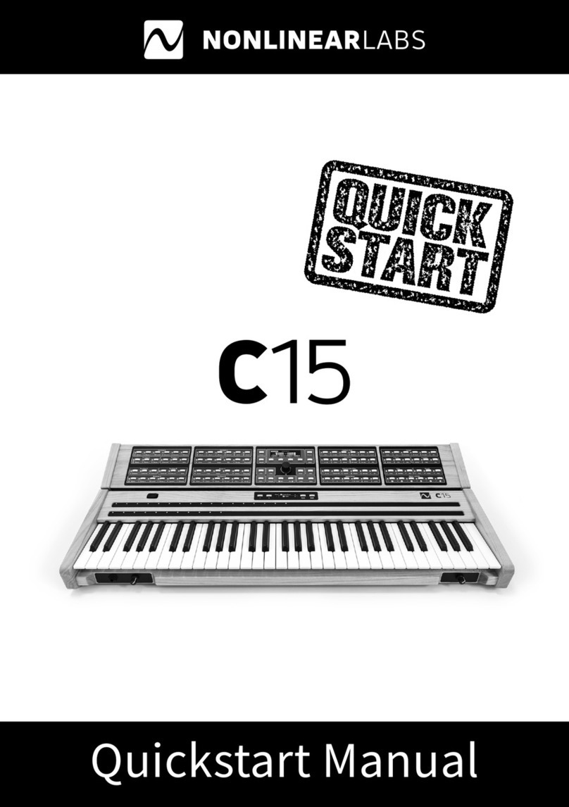
NONLINEAR LABS C15 User manual

User Manual

NONLINEAR LABS GmbH
Helmholtzstraße 2-9 E
10587 Berlin
Germany
www.nonlinear-labs.de
info@nonlinear-labs.de
Document Version: 3.2
Date: December 19, 2018
Author: Matthias Seeber
© NONLINEAR LABS GmbH, 2018, All rights reserved.

Contents
I. Safety Instructions, Precautions . . . . . . . . . . . . . . . . . 6
II. Package Contents . . . . . . . . . . . . . . . . . . . . . 8
III. Device Overview . . . . . . . . . . . . . . . . . . . . . 10
1. Introduction . . . . . . . . . . . . . . . . . . . . . . . 12
About the Manual Content . . . . . . . . . . . . . . . . . . 13
2. Setting up the C15 . . . . . . . . . . . . . . . . . . . . . 14
2.1 Mounting the Panel Unit . . . . . . . . . . . . . . . . . 14
2.2 Connections . . . . . . . . . . . . . . . . . . . . . 15
2.3 Start and Shutdown . . . . . . . . . . . . . . . . . . 17
2.4 Setting up a Device for the Graphical User Interface . . . . . . . . 18
2.5 Pedal Integration . . . . . . . . . . . . . . . . . . . 20
3. Basic Concepts . . . . . . . . . . . . . . . . . . . . . . 21
3.1 Performance (Keybed and Hardware Sources) . . . . . . . . . . 22
3.2 Macro Controls . . . . . . . . . . . . . . . . . . . . 23
3.3 Parameters . . . . . . . . . . . . . . . . . . . . . 23
3.4 Modulation Scheme . . . . . . . . . . . . . . . . . . 24
3.5 Presets . . . . . . . . . . . . . . . . . . . . . . 26
3.6 Organization . . . . . . . . . . . . . . . . . . . . . 27
3.7 The Undo Tree . . . . . . . . . . . . . . . . . . . . 27
4. User Interfaces . . . . . . . . . . . . . . . . . . . . . . 30
4.1 Selection . . . . . . . . . . . . . . . . . . . . . . 31
4.2 Editing a Parameter . . . . . . . . . . . . . . . . . . 33
4.3 Editing the Modulation of a Parameter . . . . . . . . . . . . 35
4.4 Macro Controls . . . . . . . . . . . . . . . . . . . . 37
4.5 Hardware Sources . . . . . . . . . . . . . . . . . . . 41
4.6 Presets . . . . . . . . . . . . . . . . . . . . . . 44
4.7 Contextual Info . . . . . . . . . . . . . . . . . . . . 53
4.8 Overviews . . . . . . . . . . . . . . . . . . . . . 57
4.9 The Undo Mechanism. . . . . . . . . . . . . . . . . . 59
4.10 The Rename Mechanism . . . . . . . . . . . . . . . . . 62
4.11 Sound Manipulation . . . . . . . . . . . . . . . . . . 64
4.12 Setup Navigation . . . . . . . . . . . . . . . . . . . 67
4.13 Backups . . . . . . . . . . . . . . . . . . . . . . 68
4.14 Base Unit Functionality . . . . . . . . . . . . . . . . . 69
4.15 Graphical UI Functionality . . . . . . . . . . . . . . . . 70
5. The Synthesis Engine . . . . . . . . . . . . . . . . . . . . 80
5.1 Concept . . . . . . . . . . . . . . . . . . . . . . 80
5.2 Structure . . . . . . . . . . . . . . . . . . . . . . 81
5.3 Components of the Synthesis Engine . . . . . . . . . . . . . 83
5.4 Using Hardware Sources . . . . . . . . . . . . . . . . . 108
6. Setup (C15 System Settings) . . . . . . . . . . . . . . . . . 112
7. Updating the C15 . . . . . . . . . . . . . . . . . . . . 115
8. Specifications . . . . . . . . . . . . . . . . . . . . . 116
9. Parameter Reference . . . . . . . . . . . . . . . . . . . 118
10. Shortcuts for the Graphical User Interface . . . . . . . . . . . . 160

Safety
6
Safety
7
Warning Symbols
This symbol indicates a risk of electric shock.
This symbol indicates that there are important operating and maintenance
instructions for this unit in the user manual.
Power Supply
Please consider using only the included power adapter. If this is not possible, get a power
adapter matching the following specifications:
• 19 V, DC
• 1.5 A or higher
• Plug inner contact: 2.5 mm (+)
• Plug outer contact: 5.5 mm (–)
Do not use power adapters with dierent or unknown specifications, as this may cause
electrical damage on the device! Furthermore, if an external power adapter is used, this
will be at your own risk. Nonlinear Labs will not be liable to damage caused by external
power adapters.
Things to avoid
Do not place the C15 on so surfaces (pillows, mattresses, etc.) in order to maintain air
circulation during performance.
As the C15 is an electrical (and electronical) device, strictly avoid water contact.
We strongly advise against opening the C15. The inner parts of the instrument compose
an intricate network, fragile to outside influences and potentially dangerous to the unex-
perienced seeker. We suggest to leave the device as it is unless you are absolutely certain
about what you are doing.
Try to avoid using the C15 at extreme environmental temperatures. We can not guarantee
a stable performance at very hot or cold conditions. Furthermore, try to also avoid high
humidity or other diicult circumstances.
Always wait for the shutdown process to complete before cutting the power supply. Do
not cut the power supply during performance. Otherwise, data loss can occur.
!
!
!
I. Safety Instructions, Precautions
Pedal Integration
Please avoid connecting Pedals when the C15 is running and connect them when the C15
is switched o instead. Only the booting process will recognize a Pedal’s pin assignment
and inner circuit aspects automatically.
Invalid integration of Pedals may lead to overheating or permanent damage of the C15.
A detailed explanation of Pedal integration and advanced options can be found in
chapter 5.4 Using Hardware Sources.

Package Contents
9
Package Contents
8
II. Package Contents
2×
QUICK
START
C15 Base Unit
2 Mounting BracketsPower Supply Adapter and Cable
Printed C15 Quickstart Manual Unit Connector Cable
USB stick containing:
• the preset library
• the User Manual (PDF and HTML)
The stick has a special format to be used for
installing updates. Therefore keep it safe!
C15 Panel Unit

Device Overview
10
Device Overview
11
20 Panel Unit Fixation Screw
21 Mounting Bracket for Panel Unit
22 Audio Outputs
(line level, balanced)
23 Connectors for Pedals
24 USB Connector
25 On/O Button, LED
26 Power Supply Connector
27 Unit Connector Cable
–+Funct Mode
Attack Decay 1 BP Level Deacay 2 Sustain Release
Attack Deacy 1 Decay 2 Level Vel Level KT Gain
Attack Deacy 1 BP Level Deacay 2 Sustain Release
Release Level Vel Level KT Level Vel Level KT Gain
Pitch Fluct Phase PM Self PM B PM FB
Drive Fold Asym Mix FB Mix Ring Mod
Setup
Sound
Info
Shi
Fine
Default
Enter
Undo
Edit
RedoDec (–) Inc (+)
Preset
Store
Pitch Fluct Phase PM Self PM A PM FB
Drive Fold Asym Mix FB Mix Ring Mod
Comb S.V. F. Eects Reverb Drive Level
A – B Pitch Decay AP Tune Hi Cut PM
A B Comb S.V.F. Drive Level
A – B Comb Mix Cut O Reson Spread FM
Drive Tilt Mix Center Gap Mix
Rate Env Time Mod AP Mod Feedbk Mix
Voices Volume
Time Feedback Mix Size Color Mix
ENVELOPE A
ENVELOPE C ENVELOPE A
ENVELOPE B
ENVELOPE C ENVELOPE B
OSCILLATOR A
SHAPER A
OSCILLATOR B
SHAPER B
FEEDBACK MIXER
COMB FILTER
OUTPUT MIXER
STATE VARIABLE FILTER
CABINET GAP FILTER
FLANGER
MACRO CONTROLS UNISON MASTER
ECHO REVERB
1 Base Unit
2 Panel Unit
3 Parameter Panel
4 Parameter Group
5 Parameter Selection Button
6 Parameter Selection Indicator
7 Multiple Parameter Indicator
8 Edit Panel
9 Panel Unit Display
10 Encoder
11 So Buttons
12 Base Unit Display
13 Base Unit Control Panel
14 Bender
15 Ribbon 1
16 Ribbon 2
17 Headphones Connector
18 Headphones Volume
19 Output Volume
III. Device Overview
PEDALSAUDIO OUT USB
12LR 34
➊
⓮
⓯
⓰
⓱ ⓲ ⓳
➋ ➌ ➍ ➎ ➏ ➐ ➑ ➒ ➓ ⓫ ⓬ ⓭
⓱ ⓲
⓴
⓳

Introduction
12
Introduction
13
1. Introduction
The C15 is an instrument for the performing musician, designed for playability and
detailed sound editing. Its unique sound character spans from crisp and organic to com-
plex and experimental. The top-quality semi-weighted keybed drives a digital synthesis
engine responding with a wide spectrum of sound colors and intensities.
As a dedicated real-time instrument, the C15 is built for human control. There are no
modulation sources or sequencing modules to create rhythmic patterns — we leave this
to the musician. Instead, the C15 is a decidedly responsive instrument which combines
high-resolution keys, Ribbons, and Pedal inputs.
Every parameter on the C15 can be directly selected by a button. In other words, all
functions are soware-defined but have a dedicated haptic control surface. In addition,
a Graphical User Interface can be displayed and edited on any device that has a browser
and Wi-Fi. Like many classical instrument builders, we have chosen wood for most parts
of the housing. All other parts are made of steel or aluminum. Along with the excellent
keyboard, there is a specially-designed ergonomic (pitch) Bender, two very long touch-
strips (Ribbons), and inputs for up to four Pedals.
Marks and Formats used in this Manual
Important notes begin with an exclamation mark and have a grey background:
߱Ensure that the power supply is not interrupted when using the C15 …
A hint or a background information starts with an “i” symbol:
߰If you encounter problems navigating the Setup menu intuitively, please refer to …
A section, explaining a user interaction or task has a heading on dark grey background:
Interaction
Typically, it will be first explained for the Panel Unit. If available (most times), it is followed
by an explanation for the Graphical UI and/or the Base Unit. This type of heading starts
with an arrow and has a lighter background:
→Graphical UI
→Base Unit
About the Manual Content
The following chapters refer to dierent important aspects of working with the C15 instru-
ment. Each chapter tries to exclude the „broader picture“ by focussing only on the crucial
related aspects. Nevertheless, this manual attempts to cover as many details as possible.
When using this manual, it may be helpful to first be certain about your aspect of interest,
before actually looking something up. The following overview may help clarifying:
2. Setting up the C15
At least for the first attempt of putting all components together, consider reading this
chapter describing the whole process.
3. Basic Concepts
This chapter outlines a general approach to the C15 instrument, explaining how to per-
form, how the modulation mechanism works and how everything is organized.
4. User Interfaces
This chapter explains how to actually work with the instrument. Methods of navigation,
editing and preset access are described in detail for each available interface.
5. The Synthesis Engine
All signal- or DSP- related aspects are subject of this chapter, including details on signal
synthesis and flow, tutorials as well as details on the integration of Hardware Sources.
6. Setup (C15 System Settings)
When already familiar with the instrument, the setup chapter provides insight into the
advanced system settings of the C15.

Setting up the C15
Setting up the C15
14 15
2. Setting up the C15
2.1 Mounting the Panel Unit
Ensure the C15 is switched o before following the next four steps:
Attach mounting brackets to Base Unit by
hanging and snapping.
Place Panel Unit on fixated mounting
brackets. There are two screws (mounting
pins) on the bottom side of the Panel Unit
fitting into corresponding holes near the
peak of each mounting bracket.
Tighten Panel Unit fixation screws in order
to lock Panel Unit in place.
Connect Base Unit and Panel Unit with the
Unit Connector Cable.
Now the C15 is ready to use and can be switched on. In order to disassemble the paired
setup, follow this protocol by applying the described four steps in reverse manner and
order. The C15 Base Unit can be used on its own as well.
2.2 Connections
Besides the Unit Connector Cable, the following external connections are provided by the
Base Unit:
The headphone output provides a 6.3 mm
stereo headphone socket with separate,
preset-independant adjustable headphone
level.
The audio output provides two 6.3 mm
line-level audio sockets with separate,
preset-independant adjustable output
level. The signals are transformer-balanced
and ground-free, therefore in most cases a
DI-box is not necessary. Unbalanced and
balanced plugs can be connected.
Four 6.3 mm Pedal sockets are provided for
external Pedal control. In general, any key-
board controller Pedal can be connected.
Nevertheless, only continuous Pedals
allow for a nuanced performance and are
therefore recommended.

Setting up the C15
Setting up the C15
16 17
The USB connection allows for plugging
in the USB stick, which is part of the C15
package. Via USB, preset banks can be
transferred and updates can be installed.
The C15 comes with its own external power
adapter, which can be connected to the
corresponding appliance inlet. A small LED
next to the inlet indicates the power, boot
and shut-down states of the C15.
2.3 Start and Shutdown
Turn on the C15 by pressing the power
button and holding it for around a second.
The boot process will take several seconds
before the device is ready to use. The last
settings will be loaded on startup. To shut
down the C15, press the power button and
hold it for around a second. The shutdown process will take several seconds, storing the
current settings for the next startup, before the device will turn o. A small LED next to the
inlet indicates dierent operation states of the C15 as follows:
steady lit on/normal operation
slow blinking booting
fast blinking shutting down
flashing every 2 seconds Standby mode
A flickering LED indicates an irregular operation mode. It means for example the supply
voltage is too low.
߱Ensure that the power supply is not interrupted when using the C15 (booting,
performance, shutdown) in order to prevent data loss.
Connecting Pedals and mapping Hardware Sources
Most factory presets use a mapping as shown below. For more information on Hardware
Sources and especially modulation aspects, refer to chapter 5.4 Using Hardware Sources.
Pedals
Macro
Controls
Continous
Mode !
Color 2
2
Color 1
1
Pitchbend
3
Sust Pedal
4
DP-10
Ribbons
Bender

Setting up the C15
Setting up the C15
18 19
߰If you encounter problems with your setup, there are some things you can do. If possible,
try to restart or change to another browser (or device). If not, or if the problem won’t
disappear, contact us directly. We appreciate feedback and reports of dysfunctionalities
and will try to solve problems quickly.
Wi-Fi Settings
In order to set all relevant aspects of a well defined Wi-Fi connection, enter the setup
menu on the Hardware User Interface (Setup button) and navigate to System Info. Here,
all relevant aspects of the Wi-Fi connection are listed:
Device Name You can give a name to your C15 instrument by focussing on the
device name entry and pressing enter, accessing the Rename
Screen. Once the name is set, an SSID will be generated. The SSID
is composed of a prefix (“NL-C15-”) and the name you just gave to
the instrument.
SSID A Wi-Fi network with the same name as the SSID will be provided
once you scan for available networks on your external device.
When connecting to this network, your external device will be
able to control the C15 over a browser. The SSID is generated
once during the booting process, so renaming your device will
require restarting.
Passphrase The network connection is secured, so a passphrase is needed in
order to establish a connection. When connecting to the network
from your external device, use the displayed passphrase to
confirm. The passphrase can be randomly generated by focussing
on the corresponding entry and pressing enter. The command
“generate new” has to be selected and executed. If you suspect
that the passphrase isn’t secure anymore (because it has been
shared with someone), a new passphrase should be generated.
Address 192.168.8.2
Once the connection is established, post and submit the address
into your browser’s address bar and the Graphical User Interface
should appear in your browser.
߰If you encounter problems navigating the Setup menu intuitively, please refer to chapters
4. User Interfaces and 6. Setup (C15 System Settings).
2.4 Setting up a Device for the Graphical User Interface
Concept
The C15 is designed to be of flexible usage and interaction, requiring at least the Base
Unit for connections and performance. In addition, the Panel Unit provides the Hardware
User Interface and therefore access to all parameters, presets and settings.
Finally, the Base Unit also provides a Wi-Fi hotspot in order to connect external devices,
such as smartphones, tablets, laptops and desktop computers. When connected, the
Graphical User Interface can be accessed by using a browser from the external device.
Multiple external devices can be connected simultaneously, each capable of showing
dierent features. However, only one parameter can be focussed at a time, synchronizing
the Hardware User Interface with every connected external device.
Furthermore, the Wi-Fi connection allows for preset interchange and therefore the
possibility of backing up preset banks to the external device. The C15 User Manual is also
accessible in the browser.
System Requirements
Due to the browser-based implementation of the Graphical User Interface, there are
almost no limitations concerning compatibility between operating systems or browsers.
Basically, the only required device functionalities are the device being capable of a Wi-Fi
connection and an installed browser.
However, in the wide variety of devices, operating systems and browsers, there may be
some restrictions and optimal performance can not be guaranteed. Dierences between
browsers, fast technological advances and frequent updates contribute to a complex
situation, in which it is increasingly hard to state what is suitable.
Nevertheless, there are some experiences that emerged during development and can be
expressed as a recommendation, or understood as minimal requirements:
• The device should run at least with a 1 GHz processing unit and 2 GB RAM space.
• The device display should support multi touch, or a mouse should be connected. A
connected or integrated keyboard is useful in the Graphical User Interface.
• The device display should span at least 7’’ diagonally.
• Although the choice of the browser is completely up to the user, currently (Decem-
ber2018) the best performance is achieved by using a Google Chrome browser.

Basic Concepts
21
Setting up the C15
20
3. Basic Concepts
Interaction with the C15 is possible in multiple ways, each consisting of a dierent organ-
isation and optimized layout of represented information, corresponding to the interface
used. However, the basic structure and handling remains comparable, as every interac-
tion possibility follows the main underlying principle.
These general concepts, as well as terms and keywords are subject of this chapter and
will be explained in further detail - in order to understand interaction methods on both
Hardware and Graphical User Interface, as well as the modulation mechanism and
presets. In total, there are three interfaces to consider:
The Base Unit provides access to all performance-related items (Hardware Sources,
keys). Furthermore, it can be used to edit parameters and navigate presets and banks.
Navigation of parameters is a candidate for future integration.
The Panel Unit can be used to select and edit parameters, modulation and system
settings. Presets, banks and the undo history can be navigated and managed. In short, all
relevant data can be modified on the Panel Unit.
The Graphical User Interface provides complete access to parameters and modulation
and system settings as well. In addition, there are some more helper features and settings
available. The user manual is also available as a separate HTML document.
Each interface holds items that are elements which can be interacted with (most of them
being part of a preset). In the following, items and their features will be explained in
general (before focussing on the individual interfaces in the following chapters).
Browser-specific issues
As already mentioned, there may be restrictions on some browsers, as there is no real
standard on functionality. We try to keep track of browser-specific issues and oer solu-
tions, if there are any. Please refer to the download section of our website at:
www.nonlinear-labs.de/download/download.html
and get the latest “Browser Issues” PDF.
2.5 Pedal Integration
As mentioned, the safe way of integrating Pedals into the system would be when the
C15 is switched o. Aer all connections were made, the C15 can be switched on and all
connected Pedals will be recognized and integrated accordingly. For more information
about Pedal integration, refer to chapter 5.4 Using Hardware Sources.

Basic Concepts
Basic Concepts
22 23
3.2 Macro Controls
There are four additional parameters, that don’t have any connection or eect by default.
They are called “Macro Controls” and represent the second of three modulation stages.
Macro Controls are potential modulation targets for Hardware Sources, whereas (modula-
tion target) parameters are potential targets for Macro Controls. Therefore, Macro Controls
can be seen as the center stage of the modulation mechanism, redistributing the
movements of Hardware Sources to parameters.
The purpose of a Macro Control is to be defined by the sound designer and embodies a
primary tool to bring variation into a sound, as Macro Controls are both interactive (they
can be edited) and performant (they can be modulated).
3.3 Parameters
Items that are relevant for synthesis are called parameters and are organized in groups.
Each group combines all parameters related to a particular process of the synthesis
engine (such as an envelope). Some parameters are integrated in the modulation
mechanism and can be referred to as “modulation targets”.
Currently, there are 239 parameters organized in 21 groups, 89 of the parameters working
as modulation targets.
Macro Controls
Comb
A – B
SV Filter Eects Rev Amt Drive Level
A B Comb SV Filter Drive Level
PMHi CutAP Tune
FMSpreadResonCutoComb MixA – B
DecayPitch
Feedback Mixer
Comb Filter
State Variable Filter
Output Mixer
3.1 Performance (Keybed and Hardware Sources)
The Keybed as the arguably most important performance input provides polyphonic
control over notes (currently 20 voices) and monophonic Aertouch (as shown in the le
picture above). The semi-weighted, high quality Keybed is produced by Fatar, oering 61
keys (spanning 5 octaves).
Apart from the integrated, monophonic Aertouch, there are seven additional mono-
phonic Hardware Sources supporting performance. (Currently, the whole modulation
mechanism is monophonic.) The Bender, two Ribbons (as shown in the right picture
above) and four external Pedals (as shown in the lower pictures: a continuous and a
switch Pedal) can be integrated and used for expressive play.
While performing, notes can be played (on the Keybed) and movements can be made (via
the Hardware Sources) in order to bring motion and variability into your sound.
The eight Hardware Sources are considered the first of three modulation stages, gathering
the user’s performance input and redistributing movements to the four Macro Controls.
Hardware Sources provide a variety of aspects, depending on the behavior and settings
of an individual source. To explore all related details, refer to chapter 5.4 Using Hardware
Sources.
A pressed key (le), with Aertouch (right) Bender and Ribbons

Basic Concepts
Basic Concepts
24 25
Modulation amounts define the range for target parameters in which to move according
to the corresponding Macro Control. As neither Macro Control nor the target parameter
change in position, the amount will always reflect the Macro Control position within the
modulation range (fig. 1)
There can be cases where the modulation range exceeds the parameter range, also called
virtual overdrive. When a modulation moves a parameter out of its operational range, it
will remain at the corresponding edge (clipped) until the modulation went back far
enough to fit the parameter range again (fig. 2).
When comparing unipolar and bipolar target parameters (fig. 3), it becomes obvious that
the full modulation range (-100% ... 100%) for bipolar parameters is eectively twice the
unipolar parameter modulation range (0% ... 100%).
When a target parameter has a linear scaling, the modulation amount can be displayed in
the same format, sharing the parameter’s unit. Nonlinear scalings of target parameters
require the modulation amount to be in percent (fig. 4).
More information about Hardware Sources and the modulation mechanism can be found
in chapter 5.4 Using Hardware Sources. The section „Modulation Aspects“ explains the
current standard setting, which is commonly used in the factory presets.
Macro Control Mod Amount ParameterMacro Control Mod Amount Parameter
fig. 1 fig. 2
unipolar bipolar
100 % 200 %
100 %
50 %
50 %
0 %
100 %
0 %
–100 %
150 ST 100 %
linear exponential
130 ST
55 ST
-20 ST
16000 ms
40 ms
0 ms
fig. 4fig. 3
3.4 Modulation Scheme
The modulation mechanism translates movements of the user performance (on the
Hardware Sources) into parameter movements, increasing the variation and expressivity
of a preset.
There is no automatic modulation (like an LFO - except for the Flanger) within the C15
instrument, only the user has an influence on movements.
In the sound engine, almost all parameters operate as smoothers. The smoothing time
depends on the instrument settings and operational context. (There is a smoothing time
for parameter edits, a transition time for preset recall and a smoothing time for modula-
tion as well, defined for each Macro Control, which is currently in development).
In a preset, the flow of movements is defined by several amount parameters, weighting
the amount and direction of movements. Each Hardware Source features a separate
amount for each Macro Control. Multiple Hardware Sources can aect one specific Macro
Control. Any target parameter features an MC selector and modulation amount, complet-
ing the routing of modulations. A target parameter can only follow one Macro Control.
The eect of Hardware Sources on Macro Controls is essentially dependant on the type
and settings of the source, so it is hard to generalize.
The eect of Macro Controls on target parameters on the other hand can be generalized.
Defining modulation aspects of a parameter happens in relative context to both the Macro
Control and the parameter as neither of them changes when editing modulation amounts.
External Devices Hardware Sources
Hardware Source
Macro Controls Target Parameters
Macro Control Mod Amount Parameter
Pedal 1
Pedal 2
Pedal 3
Pedal 4
MC A
MC B
MC C
MC D
Bender
Aertouch
Ribbon 1
Ribbon 2

Basic Concepts
Basic Concepts
26 27
3.6 Organization
All accessible items on the C15 instrument are organized into functional groups. Param-
eters are grouped according to their functional relations in the Sound Engine, Hardware
Sources and Macro Controls are grouped close to each other, and other items are
organized in menu structures.
The Hardware User Interface (consisting of Base and Panel Unit) provides quick access to
all parameters, which are packed in groups. However, not every parameter is accessible
by one click, as several parameters can be stacked behind one selection button.
In the Graphical User Interface, every parameter and every bank will be shown in the main
area. This requires physical space to represent all necessary information, which may not
be suiciently provided by the screen dimensions and resolutions of external devices. In
order to cope with these limitations, zooming is a crucial part of working with the Graphi-
cal User Interface, as dierent levels of detail emerge on dierent zoom levels.
3.7 The Undo Tree
The usual undo history of a program would be a list-like data structure. When an editing
action is tracked, it will be simply appended. If a certain number of edits was undone,
they will be lost when continuing with new editing actions.
However, the C15 undo history is realized as a tree-like data structure. All editing actions
will be tracked and new branches will emerge when continuing with new editing actions
(aer having undone a certain number of edits).
edit 1five editing steps:
undo three steps:
redo one step:
two new editing steps:
edit 2 edit 3 edit 4 edit 5
edit 1 edit 2 edit 3 edit 4 edit 5
edit 1 edit 2 edit 3 edit 4 edit 5
edit 1 edit 2 edit 3 edit 6 edit 7
edit 1five editing steps:
undo three steps:
redo one step:
two new editing steps:
edit 2 edit 3 edit 4 edit 5
edit 1 edit 2 edit 3 edit 4 edit 5
edit 1 edit 2 edit 3 edit 4 edit 5
edit 4 edit 5
edit 1 edit 2 edit 3 edit 6 edit 7
3.5 Presets
At any time, the current sound can be stored (and later recalled) as a preset. Presets are
organized in banks, so that every preset has a unique path (bank number/preset number).
There are some more aspects of a preset, which are explained in the following:
Preset Name
Each preset can have its own user-definable name. When storing a preset, a name will be
requested. However, the name of a preset can be changed later on.
Preset Number
The preset will have a certain position in the containing bank. Together with the bank
number, a unique number emerges for each preset and will be shown on each user inter-
face. For example, the unique number “1-001” refers to the first preset in the first bank.
Preset Info
Every preset holds a small collection of metadata, most of them being automatically
defined when storing. Besides the device name, the soware version and a time stamp,
there are elements to be defined by the user: The name of a preset can be edited, the
position in the bank can be set, a color tag can be associated and a comment text is
provided. In the comment text, sound descriptions or playing instructions can be placed.
In addition, the preset comment text will be evaluated when searching for presets with
certain keywords. This works especially well when keywords are defined as tags with the
hashtag symbol “#”.
Change Recognition
When changing a loaded preset, the system will recognize any change and indicate it
by a star symbol (“*”) behind the unique number. When storing a sound aer changes
occurred, it will be interpreted as a new preset by the system, unless the user forces
overwriting an existing preset.
More information about dealing with changes to loaded presets can be found in chapter
4.8 Overviews.
߰Note that modulations, which will change parameters, are considered as a preset change.

Basic Concepts
Basic Concepts
28 29
Using this mechanism, there will be no loss of editing steps, as all steps and branches are
accessible. Nevertheless, an ever-growing undo tree will require lots of memory and may
be capable of slowing down the system. This can be avoided by making a certain element
the new root of the tree (elements prior to that position will be lost in this case) or by
deleting inactive branches of the undo tree.
Within a branch, the mechanism is quite similar to the ordinary list-based undo, providing
backward and forward navigation via undo or redo. The extended tree-based functional-
ities emerge when navigating to other branches.
The C15 undo mechanism tracks dierent user actions. Parameter selection, edits to
parameters, preset recalls and edits to presets and banks can be undone. However, the
modulation mechanism is not integrated into the undo mechanism, as it is part of the
user performance.

User Interfaces
User Interfaces
30 31
4.1 Selection
The C15 architecture was designed to oer quick access to all items and aspects, pro-
viding one central area representing the current focus. This main principle (of focussing
on one item at a time for further editing) aects each interaction on any available user
interface. As mentioned, the current focus will be shared with all involved devices.
Selection
Parameter Panels provide Parameter
Selection Buttons. A lit LED indicates the
current focus.
Multiple parameters can be provided by
one Parameter Selection Button (indi-
cated by circles below the LED).
The Parameter Selection Button or So
Button 4 will cycle through the stack.
Macro Controls appear as a distinct group.
Pressing a Selection Button twice will
redirect to the Hardware Sources.
The Panel Unit Display will provide a
corresponding screen for the selected item.
Buttons of the Edit Panel provide access to
all item aspects.
Envelope C
Envelope A
Envelope A
Attack
Attack
Decay 1 BP Level Decay 2 Sustain Release
GainLevel KTLevel VelDecay 2Decay 1
Envelope A
Envelope A
Attack
Attack
Decay 1 BP Level Decay 2 Sustain
Release
GainLevel KTLevel VelDecay 2Decay 1
Envelope C
Setup
Sound
Preset
Store
Attack
Attack
Decay 1
Decay 1
Envelope C
Macro Controls
Info
Shi
Fine
Default
Enter
Undo
Edit
RedoDec (–) Inc (+)
Setup
Sound
Preset
Store
4. User Interfaces
As described, the C15 provides two dierent user interfaces. The Hardware User Interface
consists of both Base Unit and Panel Unit, providing haptic („hands on“) control.
The Graphical User Interface is available on external devices via Wi-Fi connection and pro-
vides a detailed parameter and preset representation. Multiple devices can be connected
in parallel, each focussing on dierent aspects.
߰Note that all available interfaces operate in a synchronized manner, sharing the same
state and focus.
The following chapters explain how to focus on items and their aspects for further editing.

User Interfaces
User Interfaces
32 33
The expandable tab area shows and provides all item-related aspects. Parameter edits
can be realized in the Parameter tab.
The chapters 4.2 to 4.6 refer to a selected parameter- or preset-related item. Further
(menu-related) items and access to them will be explained in the chapters 4.7 to 4.15)
4.2 Editing a Parameter
Adjust Control Position, coarse
Use the Encoder to adjust the currently
selected parameter.
The Dec and Inc buttons can be used for
stepwise adjustments.
→Base Unit
The Mode button can put Ribbon 1 into
Edit mode. Display and touch strip of Rib-
bon 1 will represent the currently selected
parameter, while Ribbon 2 still operates in
Play mode.
→Graphical UI
If the external device features a mouse or
touch display, use drag gestures to adjust
the currently selected parameter. (Use the
Parameter tab slider or main area element,
if GUI settings allow for it.)
If the external device features a keyboard,
K and M keys can be used for stepwise
adjustments (K for incremental, M for
decremental adjustments).
Info
Shi
Fine
Default
Enter
Undo
Edit
RedoDec (–) Inc (+)
MK
→Graphical UI
All parameters are shown in the main area and can be selected by clicking.
A highlighted element background indi-
cates the current selection. The mouse
wheel or pinch gestures on the main area
background will zoom into the provided
map. On dierent zoom levels, dierent
details emerge. High priority parameters
are always visible.
Macro Controls and Hardware Sources
appear as separate groups in the main
area, providing all related aspects.
STATE VARIABLE FILTER
FM
18.0
50.0
L - B - H
0.0
A - B
0.0
Parallel
Reson
66.0
Cut O
18.2
Spread
COMB FILTER
PM
0.0
50.0
Hi Cut
118.0
A - B
AP Tune
140.0
Decay
251
Gate
50.0
75.0
Pitch
33.0
AP Reson
OSCILLATOR A
0
PM FB
0
Shaper
120.0
Chirp
0.0
Phase
0.0
Shaper
PM Self
62.0
Fluct
0.0
Key Trk
Pitch
60.00
60.00
100.10
-22.0
PM B
0.0
ENVELOPE A
Velocity
0.0
Release
0
Curve
Decay 2
1180
Breakpoint
50.0
Attack
0.1
Decay 1
99.6
Velocity
0
0
Sustain Gain
ENVELOPE C
Velocity
0.0
Release
84.2
0
Curve
Decay 2
1040
Breakpoint
50.0
Attack
0.1
Decay 1
66.3
Velocity
0.0
0.0
Sustain
SHAPER A
Ring Mod
14.0
Mix FB Mix
CABINET
Cab LevelDrive
22.0
25.0
Asymetry
25.0
Fold
Tilt MixHi Cut
FLANGER
T ModRate Time
90.0
Phase
120.0
Hi Cut
MixAP Tune
Hi Cut
ECHO
Time Stereo
120.0
Hi Cut
MixFeedback
50.0
Cross FB
REVERB
Size Color
26.3
Pre Delay
68.3
Chorus
Mix
Comb Mix
OUTPUT MIXER
-12.0
Pan
B
-18.0
Pan
0
Pan
SV Filter
12.0
Pan
Comb
Drive
22.3
25.2
Fold
0.0
Asymetry
Drive
11.5
50.0
Fold
0.0
Asymetry
14.0
Key Pan
Level
Volume
MASTER
Tune
0.00
UNISON
Voices
1 (o)
Detune
0.000
Env C
0.0
Env C
0.0
Env A
47.0
Env B
80.0
Env C
0.0
Phase
0.0
Pan
0.0
SCALE
Env C
0.0
Key Trk
0.0
Env C
0.0
Key Trk
Env C
0.0
Key Trk
0.0
Env C
0.0
Key Trk
-14.0
Key Trk
66.0
Env C
0.0
Env A
40.0
-14.0
0.0
0.0
32.0
50.0
SHAPER B
Ring Mod
0.0
Mix FB Mix
Drive
18.0
100.0
Fold
18.0
Asymetry
11.6 47.2
AP Mod
47.8
Feedback
-67.02.7 27.8
50.0256 -9.5 50.030.0
84.0
Source
66.0 -29.0 0.025 -4.32
A
A
B
13.0
Source
50.0
Cross FB
50.0
84.2
ENVELOPE B
Velocity
0.0
Release
0
Curve
Decay 2
1180
Breakpoint
50.0
Attack
2.25
Decay 1
99.6
Velocity
0.0
15.0
Sustain
84.2
0.0
Gain
0.0
-30.0
20.0 86.3
Time KT
17.0
Level KT
-0.100
Level Vel
35.0
Env C
22.0
0.0 23.0
Env B
75.0
100.00
Env C
0.0
Key Trk
100.0
A
B
Time KT
20.0
Level KT
0.0
Level Vel
15.0
Time KT
12.0
Level KT
-0.250
Level Vel
35.0
OSCILLATOR B
33.0
PM FB
0.0
Shaper
120.0
Chirp
0.0
Phase
0.0
Shaper
PM Self
0.0
Fluct
16.0
Key Trk
Pitch
100.06
25.0
PM A
81.00
Env C
0.0
Env C
0.0
Env B
0.0
Env A
33.0
Env C
0.0
112.0-12.0
FEEDBACK MIXER
SV FilterComb ReverbEects
Drive
5.0
50.0
Fold
0
Asymetry
Level
Key Trk
0.000
0.0 0.0 25.0 -8.775.0
30.0
Lo Cut
0.0
Stereo
Base Key
C
Oset +1
0.0
Oset +2 Oset +3
0.0
Oset +4
0.0
Oset +5
0.0
Oset +6
0.0
Oset +7
0.0
Oset +8
0.0
Oset +9
0.0
Oset +10
0.0
Oset +11
0.0
0.0
ENVELOPE A
Velocity
0.0
Release
0
Curve
Decay 2
1180
Breakpoint
50.0
Attack
28.0
Decay 1
99.6
Velocity
0
0
Sustain Gain
84.2
Time KT
12.0
Level KT
-0.250
Level Vel
35.0

User Interfaces
User Interfaces
34 35
4.3 Editing the Modulation of a Parameter
Focus on Modulation Aspects
By default, the parameter’s control position
is in focus and So Button 4 can be used
to cycle through the stack if there is one.
So Button 2 can be used to make a
Macro Control assignment to the parameter. If a Macro Control is assigned, So Buttons
1and 3are also available. When focussing on a modulation aspect, So Button 4 is also
available in order to access every modulation aspect. Furthermore, the Panel Unit Display
now shows all modulation aspects. Pressing So Button 1, 2 or 3twice will set the focus
back to the parameter’s control position.
→Graphical UI
In the Parameter tab, the modulation icon
can be clicked in order to toggle the focus
on modulation aspects (if a Macro Control
is assigned, all aspects are available). The
horizontal slider represents the aspect in
focus (or the control position by default).
Elements in the main area and the selected
parameter shown in the Parameter tab
indicate their modulation aspects.
߰In chapter 4.4 Macro Controls, the Fast Mapping method is explained. It provides a quick
way of assigning target parameters to a Macro Control.
MC Selector
Press So Button 2 in order to focus on MC
selector and change the assignment like
adjusting a parameter. Either none (-) or
Macro Control (A, B, C, D) can be assigned.
→Graphical UI
Change the current MC assignment by
pressing any of the four provided assign-
ment icons (A, B, C, D). Clicking twice on an
icon will clear the assignment. This aspect
will not be in focus on the slider.
Setup
Sound
Preset
Store
If the external device features a mouse,
the mouse wheel can also be used for
adjustments when hovering over the slider
in the Parameter tab.
Adjust Control Position, fine
The Fine button toggles high resolution
mode for adjustments. An “F” indicator will
appear in the Parameter screen. Usually,
the Fine mode will be deactivated when
focussing on another parameter. However, the Fine mode can be toggled permanently
as well by holding the Shi button while pressing the Fine button. Now, the Fine mode
remains activated until the Fine button is pressed again.
→Graphical UI
While holding down the Shi key, parameter adjustments will be made in
high resolution mode.
On the slider in the Parameter tab, a pinch gesture (holding one finger while dragging
another) will allow for adjustments in high resolution.
Reset Control Position
Press the Default button to recall the
parameter’s default value.
→Graphical UI
Double click on the element in the main area (if GUI settings allow for it) or the slider in
the Parameter tab in order to recall the currently selected parameter’s default value.
Control Position Edges
Hold the Shi button and press the Dec
button for minimal, the Inc button for
maximal value.
Info
Shi
Fine
Default
Enter
Undo
Edit
RedoDec (–) Inc (+)
Setup
Sound
Preset
Store
Info
Shi
Fine
Default
Enter
Undo
Edit
RedoDec (–) Inc (+)
Info
Shi
Fine
Default
Enter
Undo
Edit
RedoDec (–) Inc (+)

User Interfaces
User Interfaces
36 37
߱These aspects are logically interconnected. Changing one will aect another.
4.4 Macro Controls
The most common practice of using Macro Controls would be the modulation mecha-
nism during user performance, accessible via the Hardware Sources.
4.4.1 Editing a Macro Control
Ribbons in Play Mode
In Play mode, Ribbons assigned to Macro
Controls will be operable. Use Mode button
to switch modes.
Adjust Macro Control Position
Adjust the selected Macro Control position
like adjusting a parameter.
→Base Unit
In Edit mode, Ribbon 1 can be used to
edit the selected Macro Control. Use Mode
button to switch modes.
→Graphical UI
In the Parameter tab, all parameter aspects
of the selected Macro Control are pro-
vided. Adjust Macro Control position like a
parameter.
Info
Shi
Fine
Default
Enter
Undo
Edit
RedoDec (–) Inc (+)
MC Position
Press So Button 1 in order to focus on MC
position and adjust it like a parameter.
→Graphical UI
Click on the MC position icon in order to
focus on MC position and adjust it like a
parameter on the slider.
߱This will cause a modulation and may aect other parameters as well.
MC Amount
Press So Button 3 in order to focus on
MC amount and adjust it like a parameter.
The modulation range will be indicated
separately, next to the slider.
→Graphical UI
Click on MC amount icon in order to focus
on MC amount and adjust it like a parame-
ter on the slider. The modulation range will
be indicated separately, next to the slider and on the main area element.
Modulation Range Aspects
Pressing So Button 4 moves the focus to
the rightmost stack of modulation range
aspects and cycles it. The selected aspect
can be adjusted like a parameter. Provided
aspects are the modulation range upper limit, the (current) control position and the
modulation range lower limit. When either the upper or lower limit exceed the parameter
range, clipping is indicated by an exclamation mark.
→Graphical UI
Click on MC Lower Limit or MC Upper Limit
icon in order to focus on modulation range
aspect and change it like adjusting a param-
eter. The control position is in focus when no aspect is selected. When either the upper or
lower limit exceed the parameter range, clipping is indicated by an exclamation mark.

User Interfaces
User Interfaces
38 39
→Graphical UI
A rename dialog appears and the label can
be edited with mouse and keyboard.
The info window appears and the info text
can be edited with mouse and keyboard.
Mod Reset (clear Target Assignments)
Assignments to target parameters of a
selected Macro Control will be reset.
Adjust Macro Control Smoothing Time
not yet implemented
4.4.3 Assigning a Macro Control to Hardware Sources
Focus on Assignment Aspects
By default, the Macro Control position is
in focus. So Buttons 1 to 4 provide focus
navigation, pressing a button twice will
return to the default focus. One Hardware
Source can be selected, and its eect on the Macro Control can be edited. When Ribbon1
is in Edit mode, the selected aspect can be edited there as well (but selection is only
available on the Panel Unit).
Fast Mapping (Panel Unit only)
When the Selection button of a potential target parameter is pressed while the Selection
button of a Macro Control is held, the assignment can easily be switched on or o. This
only works for target parameters on top of the stack.
߰This method only handles the actual mapping of target parameters to a Macro Control.
Modulation amounts have to be adjusted by focussing on each parameter. However, the
modulation amounts are preserved and will recall the last value they were adjusted to.
4.4.2 Macro Control Properties
Focus on Macro Control Properties
Press the Edit button in order to focus on
properties, provided by a stack on the right.
The stack can be cycled with So Button4.
When pressing the Enter button, the
selected property will be available in focus.
→Graphical UI
In the Parameter tab, a menu icon can be
clicked. In the main area, a right click on a
Macro Control element will also invoke a
context menu providing access to Macro
Control properties.
Rename and edit Macro Control Info
The Rename screen provides a mechanism
in order to edit the label or info text of a
selected Macro Control. So Button1 can-
cels the process, So Button4 confirms
and applies the process (see chapter 4.10
The Rename Mechanism for further details).
Macro Controls
Other manuals for C15
14
Table of contents
Other NONLINEAR LABS Synthesizer manuals
