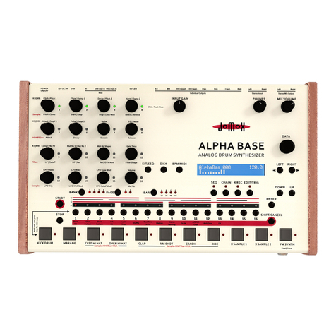
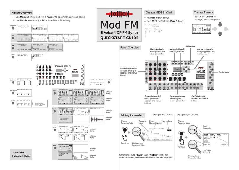
Jomox Mod FM User manual

USER MANUAL
Preliminary Version
Will be updated soon.
Please check www.jomox.de frequently.

JoMoX Elektronische Musikinstrumente GmbH
Sophie-Charlotte-Str. 15
14059 Berlin

3
JoMoX Mod FM
CONTENT
INTRO 4
What is Mod FM? 4
Installation / Rack Mounting 5
Operating Panel 7
Control Elements and Displays 7
Editing Parameters 8
Changing Presets 9
Connection Sockets 9
SOUND GENERATION 10
Signal Path Overview 10
FM Engine (Experimental Field and Key to outstanding Timbres) 10
AnalogueProcessing(EfcientParameterswithrealanalogueFlavor) 10
Effects Section (Adding sonic Spice) 10
Signal Output (Make it audible) 10
External Control (Link to the Eurorack System) 10
SignalFlow 11
Menu Overview 12
FM Engine 13
Enter the Matrix 13
Operators 14
Howtooperatethematrix 15
MatrixMenue 15
Algorithm Menue 17
OperatorEnvelopes 18
LFO Menue 19
Sound Processing 21
Filter / VCA 21
Effects (FX) 23
Randomisation and Reset Functions 25
SINGLE-/MULTIMODE 26
Single Mode 26
Multi Mode 26
STORE PRESETS 28
EXTERNAL CONTROL 29
MIDI 29
External Control via CV/Gate and Control Voltages 32
CV/Gate 32
Modulationwithexternalcontrolvoltages 32
ADDENDUM 36
FM Algorithms 36
MIDI Implementation
TechnicalSpecications 42
Imprint 43

JoMoX Mod FMINTRO 4
INTRO
WelcomeandthankyouforpurchasingyourJoMoXModFM!Wewishyoulotsofcreativefunwithyour
newJoMoXsynthesizer.
Your JoMoX team
What is Mod FM?
ModFMisaneight-voicepolyphonicFMsynthesiserwithmultimode.ItisintendedforuseinaEurorack
frameandcanbecontrolledviaMIDI(TRSorUSB-C)andCV/Gate.
Mod FM provides some interesting features:
• ModFMisself-contained-inotherwords,acompletesynthesiserinjustonesingleEurorackmodule.
Apartfromapowersupply,noothermodulesarenecessaryforoperation.
• ModFMhasahybridsoundgeneration.Thismeansthatitworksbothdigitallyandrealanalogue.
• ThedigitalpartofthesoundgenerationusesFMsynthesis,theanaloguepartcomplementsclassic
subtractivesynthesis.
• TheFMenginehasfouroperatorsthatcanbeinterconnectedinanywayviaamatrix.Fixed
FMalgorithms,asusuallyfoundinclassicFMsynthesizers,arealsoavailable.
• ModFMmakesiteasytocreateinterestingharmonictimbresandtonalsounds.Abovethat,ModFM
providesawiderangeofoutstandingandunusualtimbres.
• Thelter/VCAsectionmakesiteasytoaddrealanalogueavourtotheFMtimbres.
• ModFMsportsthreeinternalaudioeffects(reverb,2xdelay)whichaddsomemorespicetoevery
timbre.
• ModFMhasaneasytouse8channelmulti-mode.Eveninmulti-mode,ModFMcanbecontrolled
withCV/Gate.
• NumeroussoundparameterscanbecontrolledviaexternalvoltagesfromanEuroracksystem.
• Mod FM stores up to 128 single and 128 multi presets.
Rtfm...!
We pray to you: Please read (and internalise) the f... manual! You will do your-
selfabigfavour,becauseitwill(hopefully)helpyoutondaquickaccessto
your new Mod FM. And that means: more and faster fun with your new synthe-
sizer. Sounds good, eh...? Thank you so much!

JoMoX Mod FM INTROJoMoX Mod FM 5
Installation / Rack Mounting
Please power off your Eurorack prior to installation!
OnthebacksideoftheModFMmoduleyoucanndthisconnector:
RackMounting
PleaseconnecttheincludedribboncabletotheEuroracksystembusrailsasshownonthepictures.The
Mod FM module needs +/-12 Volts at a supply current of maximum 130mA on +12V and about 70mA on
-12Volts.Theoptional5VoltsandtheCV/GateontheA-100Doepferbusarebothnotwiredinsidethe
Jomox module and not needed.
Other10pinsystemsmaybeusedaswellifonlythelowerpartofthe16pinconnectorisconnected.
Pleasepayattentionforthepositionofthevoltagesandthegroundpins!Theprintedvoltageinformation
havetomatch,pleasecheckthewiresagainandmakesurenopinisleftorbent.
There are protection diodes inside the modules but please take extra care to
protect the rack and the module!
TheA-100Doepferbus.(TheDoepferGmbHenterpriseandalloftheirshownproductsareregistered
trademarks.WithfriendlyapprovalofDoepferMusikelektronikGmbH)

JoMoX Mod FMINTRO 6
TheJoMoXModFMeuroracksupplyconnector.Pleaseconnectthepowersupplyoftheeuroracksystem
bus here.
Attention: DO NOT connect, under any circumstances, the power supply cable
to the Jomox Inter-D-module bus!!!
The rack power supply and the module could get seriously damadged!
ThenpleasemountthemoduleontherackrailsusingthesuppliedmetricM3screws.Therackmountingis
nowcompletedandModFMreadytoplay.

JoMoX Mod FM INTROJoMoX Mod FM 7
Operating Panel
Control Elements and Displays
Ontheuserinterfaceyouwillndthefollowingcontrolelements:
Buttons:
• Menubuttons:
Theyareusedtoaccessthevariousmenus.
• Cursorbuttons:
Thecursorbuttons<and>areusedtochangethedisplaypageswithinamenu.
The cursor buttons and are used to change the current preset.
Knobs:
The knobssetcertainparametervalues.Dependingonthemenu,theychangetheirfunction.
Displays:
Bothdisplaysprovideinformationaboutoperatingstatesandparametersettings.Theybasicallyshow
severalpiecesofinformationandparametersatthesametime,summarisedonmenupages.
Tomakeiteasiertondyourwayaroundthedisplaycontents,thefollowingdisplaymodesapply(please
refertothegureonthenextpage):
• Onallpagesoftheleftdisplay,thetoplineshowsthecurrentpresetnameandnumber.
• Namesofmenupagesareshowninvertedandareusuallylocatedinthetopright-handcornerofthe
left-hand display.
• Aneditableparameterisshownwithashortenedname(e.g.FRQ) and a little knob symbol.
• Thepositionoftheslidermarkroughlyshowsthecurrentparametervalue.
• Ifaparametercontrolsasignallevel,alittlebarisdisplayedinsteadoftheknobsymbol.
• Whenthecorrespondingknobisturned,thedisplaybrieyshowstheparametervalueasanumber
instead of the shortened parameter name.
• Somedisplaypages-suchasenvelopecurves-areanimatedandchangetheirshapeaccordingto
thecorrespondingparametervalues.
External control of
operator envelopes
(sockets and menue
button)
External control of
matrix parameters
(sockets and menue
buttons)
CV/Gate inputs
(sockets and menue
button)
Matrix knobs for
editing matrix and
other parameters
Menue buttons for
selecting menues
Cursor buttons for
changing presets and
meneu pages
MIDI ports
Display
Display
Audio outs
Parameter knobs
for editing div.
menue parameters

JoMoX Mod FMINTRO 8
Editing Parameters
Example for the right
handeddisplay:
Example for the left
handeddisplay:
Tooptimisethelivespanofthedisplays,ascreensaverswitchesonafter30secondswithoutaninput.
Touching any control element calls up the normal display again.
• Menue buttons open the
menues.
• Cursor buttons < / >
change menue pages.
• Cursor buttons /
change the current preset.
• Knobs change parameter
settings.
(Sometimes both “Para”- and
“Matrix” knobs are used to
accessparametersshowninthe
twodisplays)
Analog Bass 1012
FRQ MIX VCO
WAV
FM1
FM2
FM3
FM4
LFO 1
Change
Parameter Value
Display shows
Parameter Value
Turn Knob
Preset
Name / Number
Parameter
Name
Menue Page
MET
FMV 2PL
4PLNOI
LP
LFO
FRQ
WAV01
LFO
INT
INP MIX
SHP
Change
Parameter Value
Level
Parameter
Any other
Parameter
Display shows
Parameter Value
Turn Knob

JoMoX Mod FM INTROJoMoX Mod FM 9
Connection Sockets
• Audio
Ontherightaretheaudiooutputsockets(individualoutputsforalleightvoices,stereomixoutput.
Theyprovideasignallevelof10Vpp(Eurorackstandard).
• MIDI
AtthetoparetheMIDIconnections(mini-TRS,USB-C).
PleasedonotuseMIDI-TRSandUSBatthesametime!
• Control Voltges
On the far left and bottom left are CV inputs for external control of sound parameters. They handle
controlvoltagesfrom0Vto5V.
• CV/Gate
AtthebottomareCV/gateinputsforpitchandtriggerofalleightvoices.ModFMhandlesgate
signalsof3Vto15V,accordingtotheEurorackstandard.
The control voltage inputs and the CV/Gate inputs of the Mod FM are
compatible with the Eurorack standard and should only be operated
with signals from suitable Eurorack modules!
External Control of
operator envelopes
(sockets and
corresponding
menue button)
External Control of
matrix parameters
(sockets and
corresponding
menue buttons)
CV/Gate inputs
(sockets and
corresponding
menue button)
MIDI Ports
Audio Outs
Changing Presets
AfterswitchingModFMon,thepresetthatwaslastactivebeforepoweringdownisalwaysactive.Itcan
bechangedatanytime.Thisworksinsingleandmultimode.
• Changethecurrentpresetwiththe/Cursor buttons.
Please note that unsaved changes will be irretrievably lost when changing
presets.Sopleasebesuretosaveyoureditedpresetsrst!(Pleasereferto
page 28).
Analog Bass 1012
TUN OVT0 AL00 VOL
C1
C2
C3
C4
MATRIX

SOUND GENERATIONSOUND GENERATION JoMoX Mod FM10
SOUND GENERATION
Signal Path Overview
FM Engine (Experimental Field and Key to outstanding Timbres)
ThesoundgenerationofModFMisbothdigitalandrealanalogue:AnFM engine servesasthemain
signalsource.Itconsistsoffour operators (sine oscillators). They are interconnected in the form of a
matrix,sothateachoperatorcanfrequency-modulateeveryotheroperatorwithindividualintensity.At
thesametime,eachoperatorcanitselftbemodulatedbyallotheroperators.
Each of these four operators sports two ADSR envelope generators.Oneofeachcontrolsthevolume
curve,theotherthepitchcurveofitsoperator.
26 preset FM-algorithms offer sensible and easy-to-use interconnections of the matrix.
A so-called overtone functionscalestheoperatorstoharmonicovertonesandthussimpliesthepro-
gramming of tonally playable sounds.
AnalogueProcessing(EfcientParameterswithrealanalogueFlavor)
The signal of the FM engine is fed into a post-processing sectionwithatrueanaloguesignalpath.It
consists of a multimode lter,aVCAaswellastwoenvelope generators and LFOs each for modulat-
ingthelterandVCA.
TheLFOscanbeoperatedintheaudiorangeandthenusedasadditionalaudiooscillatorstogetherwith
theFMengineoralternatively.
Inthissectionyouwillalsondanoise generator as a further signal source.
Effects Section (Adding sonic Spice)
Theanaluguepostprocessingsectionisfollowedbyaneffects sectionsportingthreeeffects:reverb,
delay 1 and delay 2.
Signal Output (Make it audible)
The outputsignalisavailableeitherviatheMainOut,withvoices1,3,5,7attheleftoutputchannel,and
2,4,6,8attherightoutputchannel.Nexttothis,individualoutputsforeachvoicecanbefound.
External Control (Link to the Eurorack System)
SeveralparametersoftheFMmatrixcanbecontrolledbyexternal voltages.
Theseare:
• pitchandvolumeenvelopeamountofeachoperator(EV/OP CV sockets)
• modulationamountsbetweeneachoperator(Amt 1 – 4 sockets)
• pitch of each operator (FM1 – 4 +/- sockets)
ThegureonthefollowingpageshowsasimpliedrepresentationofModFM’sentiresound
generation.
Lots of information about FM sound synthesis can be found on the internet.

JoMoX Mod FM SOUND GENERATION11
Reverb
Delay 1
Delay 2
FX Section
FM Envelope
AM Envelope
ext. CV
ext. CV
OP1
FM1
LFO1
(FM)
LFO2
(AM)
VCO Out
FM Engine
Analogue
Section
Operator 1
and
periphericals
in detail
SignalFlow
(simplied)

SOUND GENERATIONSOUND GENERATION JoMoX Mod FM12
Menu Overview
Thefollowinggureshowsallmenueswiththeircorrespondingdisplaypages.Youcanusethisasa
quickstartguideand/orasanavigationaidwhenoperatingModFM.Allmenuesandtheirfunctionswillbe
described later in detail.
OP ENV / PIT CV IN
OP 1
OP2
OP3
OP4
ENVAM PITCH
EXT OP FM CV INP
OP1 OP2 OP3 OP4
EXT OPMOD AMT CV
OP1 OP2 OP3 OP4
input calibration
remove FM cables
press SET FM
Analog Bass 1012
TUN OVT0 AL00 VOL
C1
C2
C3
C4
MATRIX
Analog Bass 1012
TUN OVT0 AL00 VOL
C1
C2
C3
C4
MATRIX
Analog Bass 1012
TUN OVT0 AL00 VOL
C1
C2
C3
C4
AM ENV
Analog Bass 1012
TUN OVT0 AL00 VOL
C1
C2
C3
C4
FM ENV
OPERAT TUNE MODE
OP1 OP2 OP3 OP4
FRQ
TUN
TUN
TUN
Analog Bass 1012
FRQ MIX LFO
WAV
FM1
FM2
FM3
FM4
LFO 1
Analog Bass 1012
FRQ MIX LFO
WAV
AM1
AM2
AM3
AM4
LFO2
Analog Bass 1012
CU RS AM TK
FIL/VCA
F
V
Single < > Multi
Single Mode
Analog Bass 1012
kickAsynth 000
Single < > Multi
Multi Mode
002
016 I 006 I 003 I
004 I 005 I 007 I 003 I
Midi Setup 1
Analog Bass 1012
RxCh CkSy
TxCh PBRg
01 01 OFF 00
Midi Setup 2
Analog Bass 1012
Splt TxCC
TxTr RxTr
0 OFF OFF ON
Midi Setup 3
SysEx Transmit
Analog Bass 1012
1Prs 1Mu1
BlkP BlkM
OFF OFF OFF OFF
Sequ Setup
Analog Bass 1012
LoRc KnRc
B 1Mu1LoP1 MiUS
OFF OFF OFF OFF
REVERB
Analog Bass 1012
LEV SIZ LP HP
DELAY 1
Analog Bass 1012
LEV
BPM120.0
1/2 SYN FBK
DELAY 2
Analog Bass 1012
LEV
BPM120.0
1/2T SYN FBK
Name edit right >
Store to location
Edit Name
Analog Bass 1012
Analog Bass 1
V / OCT CV SCALE
MTARGET OFF SCALE
0 13 27
Sing/Mul
Set EV/OP Set V/Oct
Set FM Amt Matrix left-hand
display
right-hand
display
left-hand
display
right-hand
display
left-hand
display
right-hand
display
left-hand
display
right-hand
display
LFO
Algrthm
Filter
Set FM
Midi
Store
FX
VO1 VO2 VO3 VO4
1
2
3
4
VO1 VO2 VO3 VO4
1
2
3
4
FM1 FM2 FM3 FM4
1
2
3
4
ALG 00
NO ALGORITHM
FREE MATRIX
C1 C2 C3 C4
Analog Bass 1012
FRQ
LFO1 FM
FRQ
LFO2
AM
FRQ
LFO1 FM
FRQ
LFO2
AM
MET
FMV 2PL
4PLNOI
LP
INP MIX
SHP
LFO
FRQ
WAV01
LFO
INT

JoMoX Mod FM SOUND GENERATION13
FM Engine
Enter the Matrix
ThemainsignalsourceoftheModFMisitsFMengine.Itconsistsoffouroperators(sineoscillators).They
areallinterconnectedintheformofamatrix,sothateachoperatorcanfrequency-modulateeveryother
operatorwithindividualintensities.Atthesametime,eachoperatorcanitselftbemodulatedbyallother
operators.
Operators that modulate others are usually called “modulators“ (sounds kind of sensible...). Operators that
aremodulatedbyothersarecalled“carriers”.Acarrier-or“baseoperator”-providesthefundamentaland
thusdeterminesthepitchoftheentiresound.Themodulators-or“overtoneoperators”-produce,you
guessedit,overtonesandthusdeterminethesoniccharacter.
ThefollowinggureshowstheFMmatrixwithallitsmodulationinterconnections,thecorrespondingmatrix
knobsandtherepresentationofthematrixintheleftdisplay,aswellasthecurrentlyselectedalgorithmin
the right display.
The four diagonally positioned matrix knobs “OP1” to “OP4” control the frequencies (pitches) of the four
correspondingoperators.Operatorpitchesaregenerallytunedinsemitonesbydefault.Intheso-called
overtonemode,theoperatorsaretunedaccordingtotheovertoneseries(seebelow).
The remaining 12 matrix knobs (“Amt XY”)controltheintensityofallmodulationpathsbetweenthe
operators(“FM1”to“FM4”).Thenumberscorrespondtothemodulationpaths,i.e.“Amt31”determinesthe
modulationintensityfromoperator3tooperator1,“Amt24”thatfromoperator2tooperator4,etc.
Inmatrixmode,theleft displayvisualisesthematrix,dependingofthecurrentlyselectedalgorithm.
Togetherwiththematrixknobs,itisusedforprogrammingthemodulationpathswithinthematrix.
Dependingontheselecteddisplaypage,the right displayshowsaschematicrepresentationofthe
operatorvolume-orpitchenvelopes.
Analog Bass 1012
TUN OVT0 AL00 VOL
C1
C2
C3
C4
MATRIX
VO1 VO2 VO3 VO4
1
2
3
4
FM1 FM2 FM3 FM4
1
2
3
4
Matrix Mode
left Display
Matrix Mode
right Display
OP1
OP2
OP3
OP4
OP1
OP2
OP3
OP4
ALG 00
NO ALGORITHM
FREE MATRIX
C1 C2 C3 C4
ALG 00
NO ALGORITHM
FREE MATRIX
C1 C2 C3 C4

SOUND GENERATIONSOUND GENERATION JoMoX Mod FM14
Operators:
WehavejustdealtwiththebasicfunctioningoftheFMmatrix.Nowlet’stakeacloserlookatasingle
operator.
Aswealreadyknow,anoperatorisasinewaveoscillator.Itcanmodulatethepitchofotheroperatorsand/
orcanbemodulatedinturn.Thereareseveralwaystodothis:
Modulation of the operator pitch by
• otheroperators(=>resultingintimbres)-editingwithMatrixknobs(“AmtXY”)
• FMenvelope(=>resultinginsoundprogressions)-editingwithMatrixmenue/FMenvelopepage
• LFO1(=>resultinginperiodicalsoundchanges)-editingwithLFOmenu/LFO1page
Modulation of the operator volume by
• AMenvelope(=>resultinginvolumeprogression)-editingwithMatrixmenue/AMenvelopepage
• LFO2(=>resultinginperiodicalvolumechange)-editingwithLFOmenu/LFO2page
Abovethat,boththemodulationdepthsbetweentheoperatorsandthoseofenvelopesandLFOscanbe
controlledwiththehelpofexternalvoltages.
Theinteractionofthevariousmodulationsourcesallowshighlycomplexanddynamictimbrestobe
created.
OP1
OP2
OP3
OP4
Amt 12
Amt 21
FM Envelope
AM Envelope
ext. CV
ext. CV
OP1
LFO1
(FM)
LFO2
(AM)
Thefollowinggureshowsthevariousinterconnectionsandmodulationsourcestocontrolpitchand
volumeofeachoperator:

JoMoX Mod FM SOUND GENERATION15
Howtooperatethematrix:
Matrix Menue:
Para 1 Para 2 Para 3 Para 4
Analog Bass 1012
TUN OVT0 AL00 VOL
C1
C2
C3
C4
MATRIX
The Matrix button opens the matrix menu.
Ifnopresetalgorithmiscalledup,theleft
displayshowsthecompleteFMmatrixwithall
operatorsandmodulationpathsactive.
Thefollowingparametersareavailable:
• C1/M1 to C4/M4:Pitchoftheoperators1to4–Dependingontheselectedalgorithm,the
individualoperatorsworkeitherascarriers(C)orasmodulators(M).
• AmtXY:AmountXY(showninthedisplayasaknobsymbol)–Modulationintensitiesbetweenthe
operators.
• TUN:Tuning–BasepitchoftheentireFMengine.
• OVT:Overtone–Selectstheovertonemodeoftheoperators(overtonefunction).
This overtone functionscalestheoperatorstoharmonicovertonesandthussimpliesthepro-
grammingoftonallyplayablesounds.Tounderstandexactlyhowitworks,wehavetodiveabit
deeper(Tousetheovertonefunction,youdonothavetofullyunderstandit–butknowledgedoesn’t
hurt...):
Inthe“usualcase”(i.e.OVT0),allfouroperatorsreceivethesamebasicpitchviaMIDIorCV.In
addition,theycanbedetunedindependentlyofeachotherinsemitonesoverawiderangewiththe
helpofthematrixknobsOP1toOP4.However,harmonicsarehitonly“occasionally”(i.e.whole-
numberfrequencyratiosbetweentheoperators)-andonly
then,
harmonic and tonally playable
sounds are produced.
Tosimplifythecreationofharmonicsounds,ModFMhasitsovertonemodeinwhichtheoperators
provideexclusivelyharmonicovertones.Toachievethat,the“overtoneoperators“(OT)aredecoupled
fromthefundamental(Midi,CV)andsynchronised(resp.setintorelation)tothe“basetone
operators“(BT)instead.WhenturningthematrixknobsOP1toOP4theoperatorsnowdeliverexclu-
sivelyharmonicovertones.Allintermediate,inharmonicfrequenciesareomitted.
Theovertonemodeofferssixdifferentsettingsresp.interconnectionsoffundamental-andovertone
operators(settingsOVT1toOVT6).Eachofthesesixsettingsprovidesadifferentharmonicselec-
tion,resultingindifferenttimbres.ThisworkswiththefreematrixandallFMalgorithms.
Display Content Value Knob / Button Function
C1/M1 to C4/M4 000 - 127 OP1 / OP 2 / OP 3 / OP4 Operator Pitch
000 - 127 Amt XY (12x) Operator Mod Depth
TUN 000 - 127 Para 1 Tuning entire FM Engine
OVT 0-6 Para 2 OvertoneMode
AL 00-26 Para 3 Algorithm
VOL 000 - 127 Para 4 Volume entire FM Engine

SOUND GENERATIONSOUND GENERATION JoMoX Mod FM16
Base Pitch
(Key CV
/ MIDI)
OP Pitches
(OP Knobs)
in Semitones
Overtone Mode 0:
- all Operators
receive Base Tone
- all Operator Pitches
in Semitone Steps
Harmonic
Overtones
0
127
B 1
B 1 O 2
B 2 B 3 B 4
OP1 OP2 OP3 OP4
OP Pitches
(OP Knobs)
only
Overtones
0
127
Base Pitch
(Key CV
/ MIDI) OP1 OP2
OP 2 synced to OP 1
mostly
inharmonic
Sounds
Overtone Mode 1- 6:
- only Operator 1
receives Base Tone
- OP 2 synced to OP 1
- Operator Pitches
in Overtone Steps
harmonic
Sounds
Harmonic
Overtones
0
127
Base Pitch
(Key CV
/ MIDI)
OP Pitches
(OP Knobs)
in Semitones
Overtone Mode 0:
- all Operators
receive Base Tone
- all Operator Pitches
in Semitone Steps
Harmonic
Overtones
0
127
B 1
B 1 O 2
B 2 B 3 B 4
OP1 OP2 OP3 OP4
OP Pitches
(OP Knobs)
only
Overtones
0
127
Base Pitch
(Key CV
/ MIDI) OP1 OP2
OP 2 synced to OP 1
mostly
inharmonic
Sounds
Overtone Mode 1- 6:
- only Operator 1
receives Base Tone
- OP 2 synced to OP 1
- Operator Pitches
in Overtone Steps
harmonic
Sounds
Harmonic
Overtones
0
127
Thefollowinggureillustratestheovertonemode’stheoryofoperation.Thelowerhalfcorrespondsto
overtonemode2asanexample.Forbetterclarity,onlyoperator1and2areshown.
Thefollowinggureshowsthesynchronisationbetweenthebasetone-andovertoneoperatorsinthe
differentovertonemodes0to6.Inmode“0”isnosyncbetweentheoperators(seeabove).
BASE / OVERTONE
STRUCTURE
B1 B2 B3 B4
BASE / OVERTONE
STRUCTURE
B1
O2 O3 O4
BASE / OVERTONE
STRUCTURE
B1
O2 O4
B3
BASE / OVERTONE
STRUCTURE
B1
O2 O3
B4
BASE / OVERTONE
STRUCTURE
B1
O3 O4
B2
BASE / OVERTONE
STRUCTURE
B2
B1
O4
B3
BASE / OVERTONE
STRUCTURE
O2
O1 O3
B4
0
3
6
1
4
2
5

JoMoX Mod FM SOUND GENERATION17
• AL:Algorithm–TurningthePara 3 knobselectsoneof26presetalgorithms.Eachalgorithmoffersa
differentwiringofoperatorsandprovidesdifferenttimbres.Value“00”providesthefreematrix
withnopresetalgorithmselected.Alistwiththeavailablealgorithmscanbefoundintheaddendum
onpage36.Overtonemode(seeabove)workswithallalgorithms.
Dependingonwhichoperatormodulationpathsareusedbytheparticularalgorithm,onlysomespecicof
the 12 Amt XY knobs areactive.
• VOL:Volume–setsthelevelatwhichtheoutputsignaloftheFMengineisfedintothesubse-
quentanaloguepost-processingsection.ValuesaboveXXXcanproducedeliberatesaturations
or distortions in the sound.
Analog Bass 1012
TUN OVT0 AL02 VOL
C1
C2
C3
M4
MATRIX
ALGO2
M4
M3
M2
C1
Hit the Cursor > button to select Algorithm mode page 2
“Operator Tune Mode”.Theleftdisplsyshows:
• Para 1 to Para 4knobsnowallowtogglingbetweentwo
differenttuningmodesperoperator:
• TUN:Operatoristunedinsemitones.Thisistheusual
operationmodeasweknow(andlove)it.
• FRQ:Operatoristunedtoaxedfrequency(inHertz)
thatisselectedwiththecorrespondingmatrixknob(OP1
to OP4).
Nowtheoperatorisunabletoworkinanyovertone
modes(becauseitsfrequencyisxed).Itneitherreactsto
incomming note information.
This mode is especially useful for inharmonic and noisy sounds.
OPERAT TUNE MODE
OP1 OP2 OP3 OP4
FRQ
TUN
TUN
TUN
Algorithm Menue:
When pressing the Algrthmbutton,theAlgorithmmenueopens.ActuallyitisasubmenueoftheMatrix
menuebutithasitsownselectionbutton.
Theleftdisplaystillshowstheactivematrixknobsforeditingoperatortuningandmodulationamounts.
Therightdisplayshowsaschematicrepresentationofthecurrentlyselectedalgorithm.Asanexample,the
followingguresshowalgorithm2.
ALGO2
M4
M3
M2
C1
Matrix Sceme activeMatrixKnobs left / right Display
C
M
M
M
M
OP1
OP2
OP3
OP4
OP1
OP2
OP3
OP4
Algorithm2:

SOUND GENERATIONSOUND GENERATION JoMoX Mod FM18
Hit the Cursor >buttonagaintoselectAlgorithmmodepage3.Theleftdisplayjustshowsnameand
number of the current preset.
Therightdisplayshowsananimatedwaveformofthecurrentlygeneratedsound.
Analog Bass 1012
Operator Envelopes
EachofthefouroperatorsprovidesapairofADSRenvelopegenerators.Onecontrolsthevolumecurve,
theotherthepitchcurveofitsoperator.Withthehelpoftheseenvelopes,verydynamicandpercussive
soundscanbecreated.Itrequiresalittlepracticeandexperimentationtondthemostsuitableandsoni-
callyproductivesettings.
After opening the Matrix menu (Matrixbutton),therightdisplayshowsthevolumeenvelopesofthefour
operators as a graphic. The corresponding modulation depths can be seen in the bottom line.
The > CursorbuttonswitchestotheFM(pitch)envelopepage.
TheeditingprocessisexactlythesameforbothVolume-andFMenvelope.TheexampleusestheVolume
envelope.
VO1 VO2 VO3 VO4
1
2
3
4
FM1 FM2 FM3 FM4
1
2
3
4
Analog Bass 1012
TUN OVT0 AL00 VOL
C1
C2
C3
C4
AM ENV
Analog Bass 1012
TUN OVT0 AL00 VOL
C1
C2
C3
C4
FM ENV
FM(Pitch)Envelope
VolumeEnvelope
Display Content Value Knob / Button Function
OP1EnvelopeGraphic Graphic MatrixKnobs1-4/Row1 OP1EnvelopeShape(ADSR)
OP2EnvelopeGraphic Graphic MatrixKnobs1-4/Row2 OP2EnvelopeShape(ADSR)
OP3EnvelopeGraphic Graphic MatrixKnobs1-4/Row3 OP3EnvelopeShape(ADSR)
OP4EnvelopeGraphic Graphic MatrixKnobs1-4/Row4 OP4EnvelopeShape(ADSR)
VO 1 / FM 1 000 - 127 Para 1 OP1EnvelopeMod-Amount
VO 2 / FM 2 000 - 127 Para 2 OP2EnvelopeMod-Amount
VO 3 / FM 3 000 - 127 Para 3 OP3EnvelopeMod-Amount
VO 4 / FM 4 000 - 127 Para 4 OP4EnvelopeMod-Amount

JoMoX Mod FM SOUND GENERATION19
• Envelope shape:The16Matrix knobs controltheshapeofthefouroperatorenvelopes.Each
rowcontrolstheADSR-parameterofitscorrespondingenvelope.
WhenturningaMatrixKnob,therightdisplaybrieyshowsananimatedgraphicofthecorresponding
envelopeshape.
• VO1 – VO4 :Para 1 – 4knobssetthemodulationamountsofthefouroperatorenvelopes.
LFO Menue
TheLFOmenueprovidestwomoreoscillatorswithbothtwodifferentoperationmodes.Thesetwooscilla-
torscaneitherworkasLFOsandthenmodulatethefrequency/pitch(LFO1)orvolume(LFO2)ofthefour
operators.
Alternatively,theycanworkintheaudiorangeandthenserveasadditionalsignalsourceswith64wave-
formseach.TheycanbeusedtogetherwiththeFMengineorindependently.
The LFO button opens the LFO menu.
The < / > CursorbuttonsswitchbetweenLFO1andLFO2.Theleftdisplayshowstheparametersfor
LFO1andLFO2individually.
TherightdisplayshowsparametervaluesandwaveformsofbothLFOs/VCOssimultaneously.
Thefollowingfunctionsareavailable:
Display Content Value Knob / Button Function
FM/AM 1 / 2 / 3 / 4 000 - 127 Matrix Knobs OP 1 - 4 Mod-AmountOP1–4
FRQ/DET 000 - 127 Para 1 LFO Frequency (LFO Mode)
VCO Detune (VCO Mode)
MIX 000 - 127 Para 2 VCOAudioLevelinSignalpath
LFO / VCO LFO / VCO Para 3 LFO / VCO Mode
WAV 00-63 Para 4 Waveshape
OCT (right Display) 0-6 MatrixKnobs2,3,Row1 OctavePitch(VCOModeonly)
Para 1 Para 2 Para 3 Para 4
1
2
3
4
A D S R
VO1 VO2 VO3 VO4
1
2
3
4
1

SOUND GENERATIONSOUND GENERATION JoMoX Mod FM20
Para 1 Para 2 Para 3 Para 4
Analog Bass 1012
FRQ MIX LFO
WAV
FM1
FM2
FM3
FM4
LFO 1 FRQ
LFO1 FM
FRQ
LFO2
AM
BothLFO1andLFO2inLFOMode
• FM1 - FM4(LFO1):ModulationdepthforthefrequencyoftheoperatorsOP1toOP4.Itissetwith
the four corresponding matrix knobs OP1 to OP4.
• AM1 - AM4(LFO2):ModulationdepthforthevolumeoftheoperatorsOP1toOP4.Itissetwiththe
four corresponding matrix knobs OP1 to OP4.
• FRQ / DET:-LFOfrequency(inLFOmode).
- Detune of the VCOs to each other and to the FM engine (in VCO mode).
• MIX:MixesthesignaloftheLFOsorVCOsintothesignalpath.(ThisalsoworksinLFOmodeand
can be sonically interesting).
• LFO / VCO:Operatingmode-togglesbetweenLFOandVCOmode.
WhensettoVCO,thecorrespondingoscillatorworksintheaudiorangeandcanbeusedasan
additionalsoundsource,togetheroralternativelytotheFMengine.
• WAV:Waveform–thereare64differentwaveformstochoosefrominbothmodes.
InVCOmode,thereisonemorefunctionavailableintherightdisplay:
• OCT:Octave–selectstheoctavepositionoftheVCOinarangeofsevenoctaves(0-6)
BothLFO1andLFO2inVCOMode
Para 1 Para 2 Para 3 Para 4
etc.
Analog Bass 1012
FRQ MIX VCO
WAV
FM1
FM2
FM3
FM4
LFO 1 DET
VCO1
OCT 3 OCT 5
MX
DET
VCO2
MX
Other manuals for Mod FM
1
Table of contents
Other Jomox Synthesizer manuals