NookBox DIO-52-ZBS User manual

1NookBox Installation Guide Input and Output Switch DIO-52-ZBS
Input & Output Switch
(DIO-52-ZBS)
Installation Guide

2NookBox Installation Guide Input and Output Switch DIO-52-ZBS
DIO-52 is a ZigBee Input and Output Switch. The switch has built-in Digital Input and Digital
Output terminals which can be connected to sensor, switch, or devices to form Normal Open
(N.O.) or Normal Close (N.C.) loop. When the Input terminal is triggered, the Switch will trans-
mit signal via ZigBee network to inform the ZigBee network panel/coordinator; the Switch can
also receive command signal via ZigBee network to turn on/o the Output terminal to control
connected device.
The Switch utilizes ZigBee technology for wireless signal transmission. ZigBee is a wireless
communication protocol that is reliable, has low power consumption and has high transmissi-
on eciency. Based on the IEEE802.15.4 standard, ZigBee allows a large amount of devices to
be included in a network and coordinated for data exchange and signal transmission.
The switch can either be connected to a single device for remotely controlling it from the
ZigBee network panel/coordinator, or connected to separate devices with the input terminal
as the trigger of events and the output terminal as the responder of events.
The Switch also serves as an end device in the ZigBee network. It can be included in the Zig-
Bee network to transmit or receive signal, but cannot permit any other ZigBee device to join
the network through the Switch.
Input & Output Switch
(DIO-52-ZBS)

3NookBox Installation Guide Input and Output Switch DIO-52-ZBS
Parts Identication
1. Function Button
- Press once to send a supervision signal.
- Press and hold for 10 seconds until the LED ash once, then release to reset the Switch.
2. LED Indicator
The LED indicator lights up in the following conditions:
Flashes once:
When the user presses and holds the function button for 10 seconds,
the LED will ash once to indicate that the button can be released for
the Switch to join the ZigBee network.
Flashes twice quickly:
The Switch has successfully joined a ZigBee network.
3. Battery Compartment
4. Power Terminal
5. Input Terminal
Set Normal Open (N.O.) or Normal Close (N.C.)
for the device connected to the input terminal from the Control Panel webpage.
6. Output Terminal
Set Normal Open (N.O.) or Normal Close (N.C.)
for the device connected to the input terminal from the Control Panel webpage.
7. Mounting Holes
Set Normal Open (N.O.) or Normal Close (N.C.) for the device connected
to the output terminal from the Control Panel webpage.
8. Strain Relief Clamps
The clamps are used for securing the wires, and providing strain
relief to protect the wires from metal cutout.
9. Wiring Holes

4NookBox Installation Guide Input and Output Switch DIO-52-ZBS
Features
Output and Input Terminal
• Output Terminal (DO):
The output terminal is controlled by the Control Panel; when the Switch receives on/o signal, it will turn on or o the output terminal
accordingly.
When set to N.O., the output terminal will close upon receiving ON signal, and open upon receiving OFF signal.
When set to N.C. the output terminal will close upon receiving OFF signal, and open upon receiving ON signal.
• Input Terminal (DI):
When set to N.O. the input terminal will send a trigger signal to the Control Panel when the loop closes, and send a restore signal when
the loop opens.
When set to N.C. the input terminal will send a trigger signal to the Control Panel when the loop opens, and send a restore signal when
the loop closes.
NOTE:
• The Input Terminal and Output terminal can be set to either Normal Close (N.C.) or Normal Open (N.O.) from the DO conguration page
of the Control Panel webpage.
Select Invert Input as Yes or No to set the input terminal to N.C. / N.O.
Select Invert Output as Yes or No to set the output terminal to N.C. / N.O.
• The status descriptions for the Input Terminal (DI) and Output terminal (DO) are editable from the DI and DO conguration pages.
Operation Mode
The Input and Output Switch can operate according to dierent mode selected in the Control Panel.
• Appliance Control:
When DIO-52 is used for appliance control, the input and output terminals are connected to the same device, e.g. a valve.
The output terminal is used to receive on/o signal from the Control Panel to turn/on o the connected device, while the input terminal
is used to transmit the current status of the connected device to the Panel.
• Separate Devices:
In this mode, the input and output terminals of DIO-52 are connected to separate devices. The input terminal is used to monitor the
activation of the connected device, and transmit the trigger signal to the Control Panel. The output terminal is used to receive on/
o signal from the Control Panel to turn/on o the connected device. When working under this mode, the connected devices of DIO-52
can integrate with other devices included in the Control Panel, and operate according to the Home Automation rules programmed in
the Control Panel.

5NookBox Installation Guide Input and Output Switch DIO-52-ZBS
• Input Follower:
In this mode, the input and output terminals of DIO-52 are connected to separate devices, and the output terminal device will act following
the trigger of input terminal device.
When input terminal device is triggered and sends a signal to the Control Panel, the output terminal device will be activated according to
the Output Follow Input settings in the Control Panel.
Power Terminal
The Switch uses two-wired 5-12V DC adapter to power on when connected to the Power Terminal. When Power Terminal and batteries are
both in use, the Switch will only power through AC Adapter.
Battery and Low Battery Detection
The Switch uses three CR123 Lithium batteries as its power source. The Switch features Low Battery Detection function. When the battery
voltage is low, the Switch will transmit Low Battery signal to the Control Panel to notify the user. When changing batteries, after removing
the old batteries, press the Function Button twice to fully discharge before inserting new batteries.
Supervision
The Switch will transmit a supervision signal to report its condition regularly according to user setting. The factory default interval is 30
minutes. The user can also press the Function Button once to transmit a supervision signal manually.
ZigBee Network Setup
ZigBee Device Guideline
ZigBee is a wireless communication protocol that is reliable, has low power consumption and has high transmission eciency. Based on
the IEEE802.15.4 standard, ZigBee allows a large amount of devices to be included in a network and are coordinated for data exchange and
signal transmission.
Joining the ZigBee Network
As a ZigBee device, the Switch needs to join a ZigBee network to transmit signal when it is triggered. Please follow the steps below to add
the Switch into the ZigBee network.
The Switch can only join ZigBee network within 3 minutes after power on.
1. Insert batteries or connect the two-wired 5-12V DC adapter to power on the Switch.
2. Within 3 minutes after power up, press and hold the Function button for 10 seconds, then release it to join the network. Please
make sure the permit-join feature on the router or coordinator of your ZigBee network is enabled.
3. If the Switch successfully joins a ZigBee network, the LED Indicator will ash twice to conrm.
4. After joining the ZigBee network, the Switch will be registered in the network automatically. Please check the ZigBee coordinator,
system control panel or CIE (Control and Indicating Equipment) to conrm if joining and registration is successful.
5. After joining the ZigBee network, if the Switch loses connection to current ZigBee network, the LED will ash every 20 minutes to
indicate. Please check your ZigBee network condition and Switch signal range to correct the situation.
NOTE: When learnt into the ZigBee Control Panel, the DIO-52 will be recognized as 2 separate devices (DI & DO) and will occupy 2 zones in
the Panel.

6NookBox Installation Guide Input and Output Switch DIO-52-ZBS
Factory Reset
If you want to remove the Switch from current network and join a new network, you need to use the Factory Reset function to clear the
Switch for its stored setting and information rst before it can join another network. To perform Factory Reset:
1. The Switch can only be reset within 3 minutes after power up. If the Switch has been powered
up for more than 3 minutes, power down the Switch by removing the battery/two-wired AC
Adapter, then reinsert the battery / Connect two-wired AC Adapter again.
2. Press and hold the function button for 10 seconds then release.
3. The Switch has been reset to factory default setting with all its previous network information removed. It will now actively search for
available ZigBee network again and join the network automatically.
4. If the Switch successfully joins a ZigBee network, the LED Indicator will ash twice to indicate.
OTA Firmware Upgrade (For OTA version only)
The Switch supports OTA rmware upgrade feature via ZigBee network, which can be initiated from the ZigBee network coordinator. Fol-
low steps below to perform OTA rmware upgrade.
Step 1. You have to access your ZigBee Coordinator to perform the rmware upgrade on the air.
Step 2. On the conguration webpage, select the device that you wish to upgrade and select the
new ZigBee rmware provided. Please refer to ZigBee Coordinator User Manual for details.
Step 3. Press OK to start upgrading process, and the LED will keep ashing. During the OTA process, please do not perform any other
actions, or power down the panel.
Step 4. The length of an upgrade will take approximately 20 to 30 minutes. Please note that the
duration may vary based on le size or distance between your accessory and coordinator.
Step 5. Wait for rmware to complete update. When the progress reaches 100%, the Device will reset automatically. You can also refresh
the webpage again to ensure that the Device rmware is successfully updated with the newest version displayed.
Installation
The Switch can be deployed on a at surface or mounted on the wall.
1. Disconnect the main power supply.
2. Loosen the bottom xing screw and remove the top cover of the Switch.
3. Use the holes on the base to mark mounting location on the wall.
4. Drill holes into marked location and insert wall plugs if required, screw the base onto the mounting location.
5. Replace the top cover and tighten the bottom xing screw.

7NookBox Installation Guide Input and Output Switch DIO-52-ZBS

8NookBox Installation Guide Input and Output Switch DIO-52-ZBS

9NookBox Installation Guide Input and Output Switch DIO-52-ZBS

10NookBox Installation Guide Input and Output Switch DIO-52-ZBS
For more information visit:
www.getnookbox.com
Other manuals for DIO-52-ZBS
1
Table of contents
Other NookBox Switch manuals
Popular Switch manuals by other brands
Ubiquiti
Ubiquiti UniFi USW-24-POE quick start guide

Siemens
Siemens S 564 Operating and mounting instructions
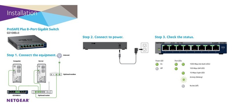
NETGEAR
NETGEAR ProSAFE Plus GS108Ev3 installation guide
Enabling Devices
Enabling Devices Switch & Glow 894 user guide
BleBox
BleBox switchboxD user manual

AETEK
AETEK C50-082-30-130 Quick installation guide
