NookBox DIO-52-ZBS User manual

1NookBox Installation Guide Input and Output Switch DIO-52-ZBS
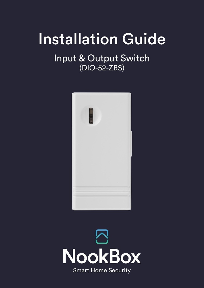
Input & Output Switch
(DIO-52-ZBS)
Installation Guide

2NookBox Installation Guide Input and Output Switch DIO-52-ZBS
DIO-50 is a ZigBee Input and Output Switch. The switch has built-in Digital Input and Digital
Output terminals which can be connected to sensor, switch, or devices to form Normal Open
(N.O.) or Normal Close loop. When the Input terminal is triggered, the Switch will transmit
signal via ZigBee network to inform the ZigBee network panel/coordinator; the Switch can
also receive command signal via ZigBee network to turn on/o the Output terminal to control
connected device.
The Switch utilizes ZigBee technology for wireless signal transmission. ZigBee is a wireless
communication protocol that is reliable, has low power consumption and has high transmissi-
on eciency. Based on the IEEE802.15.4 standard, ZigBee allows a large amount of devices to
be included in a network and coordinated for data exchange and signal transmission.
The Switch serves as an end device in the ZigBee network. It can be included in the ZigBee
network to transmit or receive signal, but cannot permit any other ZigBee device to join the
network through the Switch.
Input & Output Switch
(DIO-52-ZBS)

3NookBox Installation Guide Input and Output Switch DIO-52-ZBS
Parts Identication
1. Function Button / LED Indicator
Function Button
- Press once to send a supervision signal.
- Press and hold for 10 seconds until the LED ash once, then release to reset the Switch.
LED Indication
The LED indicator lights up in the following conditions:
- Flashes once:
When the user presses and holds the function button for 10 seconds,
the LED will ash once to indicate that the button can be released for
the Switch to join the ZigBee network.
- Flashes twice quickly:
The Switch has successfully joined a ZigBee network.
- Flashes once every 20 minutes:
The Switch has lost connection to its current ZigBee network.
2. Front Cover Hook
Press the hook to release front cover.
3. Output Jumper (JP2)
To set Normally Closed or Normally Open through Output jumper 2:
-Normally Closed (N.C): the jumper link is parked on both PIN1 and PIN2.
-Normally Open (N.O): the jumper link is parked on both PIN2 and PIN3.
4. Ouput Terminal
Use Jumper 2 to set Normal Open (N.O.) or Normal Close (N.C.) for
the device/switch connected to the terminal.
5. Input Terminal
Use Jumper 3 to set Normal Open (N.O.) or Normal Close (N.C.) for
the device/switch connected to the terminal.
6. Power Terminal
7. Battery Compartment
8. Input Jumper (JP3)
9. Mounting Bracket

4NookBox Installation Guide Input and Output Switch DIO-52-ZBS
Features
Output Terminal:
The output terminal is controlled by the Control Panel; when the Switch receives on/o signal, it will turn on or o the output terminal
accordingly. When jumper2 is set to N.C., sending an open/close signal from the Control Panel will open/close the loop. When jumper2 is set
to N.O., sending an open/close signal from the Control Panel will close/open the loop.
Input Terminal:
When the device is triggered, the Switch will transmit a “close” signal back to the Control Panel whether jumper 3 is set to N.O or N.C.
<NOTE>
When the Input Jumper (JP3) needs to be changed from Normally Close (N.C.) to Normally Open (N.O.), it is not required to remove the
battery or power down rst.
Power Terminal:
The Switch uses two-wired 12DC adapter to power on when connected to the Power Terminal. When Power Terminal and battery are both in
use, the Switch will only power through AC Adapter.
Battery and Low Battery Detection:
The Switch uses one CR2 3V Lithium battery as its power source. The Switch features Low Battery Detection function. When the battery vol-
tage is low, the Switch will transmit Low Battery signal to the Control Panel to notify the user. When changing battery, after removing the old
battery, press the Function Button twice to fully discharge before inserting new battery
Supervision:
The Switch will transmit a supervision signal to report its condition regularly according to user setting. The factory default interval is 30
minutes. The user can also press the Function Button once to transmit a supervision signal manually.

5NookBox Installation Guide Input and Output Switch DIO-52-ZBS
ZigBee Network Setup
ZigBee Device Guideline:
ZigBee is a wireless communication protocol that is reliable, has low power consumption and has high transmission eciency. Based on the
IEEE802.15.4 standard, ZigBee allows a large amount of devices to be included in a network and are coordinated for data exchange and signal
transmission.
Joining the ZigBee Network:
As a ZigBee device, the Switch needs to join a ZigBee network to transmit signal when it is triggered. Please follow the steps below to add the
Switch into the ZigBee network.
1. Use the two-wired 12DC adapter or insert battery to power on the Switch.
2. After powering up, press and hold the Function button for 10 seconds, then release it to join the network. Please make sure the permit-join
feature on the router or coordinator of your ZigBee network is enabled.
3. If the Switch successfully joins a ZigBee network, the LED Indicator will ash twice to conrm.
4. After joining the ZigBee network, the Switch will be registered in the network automatically. Please check the ZigBee coordinator, system
control panel or CIE (Control and Indicating Equipment) to conrm if joining and registration is successful.
5. After joining the ZigBee network, if the Switch loses connection to current ZigBee network, the LED will ash every 20 minutes to indicate.
Please check your ZigBee network condition and Switch signal range to correct the situation.
Factory Reset:
If you want to remove the Switch from current network and join a new network, you need to use the Factory Reset function to clear the Switch
for its stored setting and information rst before it can join another network. To perform Factory Reset:
1. Press and hold the function button for 10 seconds then release.
2. The Switch has been reset to factory default setting with all its previous network information removed. It will now actively search for
available ZigBee network again and join the network automatically.
3. If the Switch successfully joins a ZigBee network, the LED Indicator will ash twice to indicate.
Installation
The Switch can be installed on a at surface. You can choose to mount the switch with or without bracket using screws or double-sided
adhesive tape.
Without Bracket:
1. Remove the front cover. Use the mounting holes on the back cover as template to mark mounting location.
2. Screw the back cover onto marked location, drill holes and install wall plugs if required.
3. Replace the front cover.
With Bracket:
1. Use the mounting holes on the mounting bracket as template to mark mounting location.
2. Screw the mounting bracket onto marked location, drill holes and install wall plugs if required.
3. Hook the switch onto the hooks on the bracket and slide upward to secure.

6NookBox Installation Guide Input and Output Switch DIO-52-ZBS
Appendix

7NookBox Installation Guide Input and Output Switch DIO-52-ZBS
Appendix

8NookBox Installation Guide Input and Output Switch DIO-52-ZBS
For more information visit:
www.getnookbox.com
Other manuals for DIO-52-ZBS
1
Table of contents
Other NookBox Switch manuals
Popular Switch manuals by other brands
StarTech.com
StarTech.com VS221DP instruction manual
GRASS VALLEY
GRASS VALLEY KAYAK HD Installation and service manual

AVE
AVE UTP 4X1500 installation manual
schmersal
schmersal AZM300B-ST-1P2P-A-T installation instructions
Edge-Core
Edge-Core AS7712-32X Safety and regulatory information
Digisol
Digisol DG-GS1008PF Quick installation guide
Black Box
Black Box LB9020A-R2 manual
ICP DAS USA
ICP DAS USA NS-208PSE-IP67 quick start guide
Mercoid
Mercoid A1F Series Specifications-installation and operating instructions
INTALITE
INTALITE INTALED TSS-3G manual
BZB Gear
BZB Gear BG-UHD-KVM41 user manual
Southern States
Southern States EC-1 Installation instructions manual
